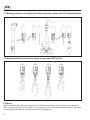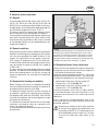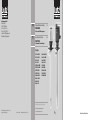
1
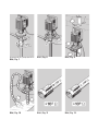
Lutz Pumpen GmbH Erlenstraße 5-7 D-97877 Wertheim Tel. (0 93 42) 8 79-0 Fax (0 93 42) 87 94 04 e-mail: [email protected] http://www.lutz-pumpen.de DE Originalbetriebsanleitung Pumpwerke 5–12 für Fass- und Behälterpumpen GB Operating Instructions Pump tubes 13–20 for Drum and Container Pumps Typ/Type PP 41-R-GLRD PP 41-L-GLRD PP 41-R-DL PP 41-L-DL PVDF 41-R-GLRD PVDF 41-L-GLRD PVDF 41-R-DL PVDF 41-L-DL Alu 41-R-GLRD Alu 41-L-GLRD Alu 41-R-DL Alu 41-L-DL Niro 41-R-GLRD Niro 41-L-GLRD Niro 41-R-DL Niro 41-L-DL HC 42-R-DL RE-PP-GLRD RE-Niro-GLRD MP-PP-GLRD MP-Niro-GLRD Vor Inbetriebnahme Betriebsanleitung lesen! Read this operating instructions before start up! Für künftige Verwendung aufbewahren. To be retained for future reference. Technische Änderungen vorbehalten. 07/08 Subject to technical changes. Best.-Nr. 0698-030 Printed in Germany Hi. 5.000/01.09 Illustrationen/Illustrations Bild / Fig. 1 Bild / Fig. 2 Bild / Fig. 3 Bild / Fig. 4 Bild / Fig. 5 Pumpwerk RE Niro / pump tube RE SS Bild / Fig. 6 Pumpwerk RE PP / pump tube RE PP Bild / Fig. 8 Bild / Fig. 9 Bild / Fig. 10 Bild / Fig. 11 Bild / Fig. 12 Bild / Fig. 7 DE DE Inhaltsverzeichnis 1. Allgemeines ..................................................................................... 6 1.1 Lieferumfang.............................................................................. 6 2. Pumpwerke....................................................................................... 7 2.1 Pumpwerke................................................................................ 7 2.2 Restentleerungspumpwerk RE................................................... 7 2.3 Mischpumpwerk MP.................................................................. 7 3. Einsatzbedingungen.......................................................................... 7 7 3.1 Beständigkeit der Pumpwerke.................................................... 3.2 Mediumstemperatur.................................................................. 7 3.3 Viskosität................................................................................... 7 3.4 Dichte........................................................................................ 7 4. Inbetriebnahme................................................................................. 8 8 4.1 Montage am Motor.................................................................... 8 4.2 Befestigen des Pumpwerks........................................................ 4.3 Mechanische Belastung des Pumpwerks................................... 8 4.4 Maximale Eintauchtiefe.............................................................. 8 4.5 Verwendung eines Fußsiebes..................................................... 8 8 5. Bedienung......................................................................................... 5.1 Restentleerung........................................................................... 8 5.2 Restentleerung mit Pumpwerk RE............................................. 8 5.3 Mischen mit Pumpwerk MP....................................................... 9 5.4 Trockenlauf................................................................................ 9 9 5.5 Entnahme des Pumpwerks........................................................ 6. Lagerung........................................................................................... 9 7. Wartung............................................................................................ 9 7.1 Montageanleitung zum Wechseln des Gleitringträgers bei Pumpwerk PP 41 GLRD....................... 10 7.2 Montageanleitung für Distanzhülse bei Pumpwerken PVDF und Alu................................................. 10 8. Reparaturen...................................................................................... 10 9. Explosionsgeschützte Pumpwerke.................................................... 11 9.1 Allgemeines............................................................................... 11 9.2 Besondere Bedingungen............................................................ 11 9.3 Potentialausgleich und Erdung.................................................. 11 9.4 Leitfähige Schläuche/Schlaucheinbindungen............................. 11 9.5 Vorschriften zum Explosionsschutz........................................... 12 9.6 Zoneneinteilung für explosionsgefährdete Bereiche................... 12 9.7 Erläuterung der Zoneneinteilung bei der Anwendung von Fasspumpen für brennbare Flüssigkeiten............................ 12 9.8 Rückverfolgbarkeit..................................................................... 12 EG-Konformitätserklärung......................................................... 26/27 DE Allgemeine Sicherheitshinweise 1. Allgemeines Die Betriebsanleitung ist vor Inbetriebnahme vom Bediener des Pumpwerks zu lesen und die Hinweise sind während des Betriebs einzuhalten. 1. Die bestimmungsgerechte Gebrauchslage des Pumpwerks ist senkrecht. 2. Tragen Sie beim Fördern gefährlicher Flüssigkeiten (z.B. ätzend, heiß, giftig usw.) passende Schutzkleidung wie Gesichtsmaske oder Schutzbrille, Schürze und Handschuhe. Setzen Sie gegebenenfalls Emissionsschutzsysteme ein. 3. Beachten Sie, dass alle Anschlüsse und Verbindungen richtig befestigt sind. 4. Beachten Sie die Grenzwerte für Temperatur, Viskosität und Dichte der Förderflüssigkeit. 5. Verwenden Sie bei stark verschmutzten Flüssigkeiten ein Fußsieb. 6. Nicht in die Ansaugöffnung der Pumpe fassen. 7. Pumpe sollte nicht trockenlaufen. 8. Im Betrieb kann es bei niedrigem Füllstand im Behälter am Pumpenfuß spritzen. Verwenden Sie beim Einsatz von gefährlichen Flüssigkeiten Behälter mit Abdeckungen. 9. Beachten Sie die Betriebsanleitung des Motors. Eine elektrische Fass- und Behälterpumpe besteht aus einem Antriebsmotor und einem Pumpwerk. Für den Antrieb der Pumpe sind Wechselstrom-, Drehstrom- und Druckluftmotoren in unterschiedlichen Ausführungen (z.B. explosionsgeschützt) und Leistungsbereichen einsetzbar. Die Pumpwerke werden in unterschiedlichen Werkstoffen, Dichtungsarten und Förderradformen angeboten. Dadurch kann die Pumpe auf den jeweiligen Einsatzfall bezüglich Fördermenge, Förderhöhe und den Eigenschaften der Flüssigkeit abgestimmt werden. Weiterhin gilt für Pumpwerke aus Polypropylen (PP), Polyvinylidenfluorid (PVDF) und Aluminium (Alu): 1. Pumpe darf nicht in explosionsgefährdeter Umgebung verwendet werden. 2. Es dürfen keine brennbaren Flüssigkeiten gefördert werden. Die Einstufung brennbarer Flüssigkeiten erfolgt nach Richtlinie 67/548/EWG. Beim Fördern brennbarer Flüssigkeiten sind die Betriebssicherheitsverordnung und die nachfolgenden Punkte zu beachten: 1. Nur Pumpwerke aus Edelstahl (Niro 1.4571) oder Hastelloy C (HC) verwenden. 2. Nur explosionsgeschützte Antriebsmotoren verwenden. 3. Nur Einsatz in ortsveränderlichen Behältern zugelassen. 4. Vor Pumpbeginn Potentialausgleich zwischen Pumpwerk und Behältnis herstellen. 5. Leitfähige Druckschläuche verwenden. 6. Der Betrieb der Pumpe muss überwacht werden. 7. Instandsetzung nur durch den Hersteller oder autorisierte Vertragswerkstätten. Die Unfallverhütungsvorschriften des jeweiligen Landes sind unbedingt einzuhalten. 1.1 Lieferumfang Die Verpackung kann ebenfalls bestellte Zubehörteile enthalten. Prüfen Sie deshalb die Lieferung mit Hilfe der Bestellung auf Vollständigkeit. DE 2. Pumpwerke 3. Einsatzbedingungen 2.1 Pumpwerke 3.1 Beständigkeit der Pumpwerke Pumpwerke aus Polypropylen (PP), Polyvinylidenfluorid (PVDF), Aluminium (Alu) oder Edelstahl (Niro 1.4571) sind je nach Anforderung an Fördermenge und Förderhöhe entweder mit einem axialen (Kennbuchstabe R) oder mit einem radialen (Kennbuchstabe L) Förderrad ausgerüstet und kommen zudem in zwei Dichtungsausführungen (DL = dichtungslos oder GLRD = Gleitringdichtung) zur Auslieferung. Pumpwerke aus Hastelloy C (HC) sind grundsätzlich dichtungslos und mit axialem Förderrad (R) ausgerüstet. Die Pumpwerke sind nur für den vertikalen Einsatz vorzusehen. Die Pumpwerke dienen zum Fördern reiner, getrübter, aggressiver und nicht aggressiver Flüssigkeiten, wobei jedoch die benetzten Pumpwerksmaterialien gegenüber dem Fördermedium beständig sein müssen. Prüfen Sie anhand einer Beständigkeitstabelle (z.B. Lutz-Beständigkeitstabelle) und der Werkstoffauflistung Tabelle 1 (siehe Seite 21), ob das Pumpwerk für die Förderflüssigkeit geeignet ist. 2.2 Restentleerungspumpwerk RE Restentleerungspumpwerke aus Polypropylen (PP) oder Edelstahl (Niro 1.4571) dienen zur vollständigen Entleerung von Fässern und Behältern. Durch das Absenken des Verschlusstopfes kann der Pumpenfuß bei noch laufenden Motor innerhalb des Pumpwerks verschlossen werden. Dies verhindert das Zurücklaufen der bereits angesaugten Flüssigkeit nach dem Abstellen der Pumpe. Das Schließen oder Öffnen des Verschlusstopfes erfolgt manuell über einen Hebel unterhalb des Handrades. RE-Pumpwerke sind mit einem radialen Förderrad und Gleitringdichtung ausgerüstet. Die Pumpwerke sind nur für den vertikalen Einsatz vorzusehen. 2.3 Mischpumpwerk MP 3.2 Mediumstemperatur Die Mediumstemperatur darf die Werte in Tabelle 2 (siehe Seite 22) nicht überschreiten. 3.3 Viskosität Das Pumpen von zähen Flüssigkeiten verlangt dem Antriebsmotor eine höhere Leistung ab. Durch viskose Fördermedien reduzieren sich die Förderhöhe und die Fördermenge. Um den Motor nicht zu überlasten müssen die Viskositätsgrenzen in Tabelle 3 (siehe Seite 23) beachtet werden. 3.4 Dichte Das Fördern von Flüssigkeiten mit hoher spezifischer Dichte verlangt dem Antriebsmotor eine höhere Leistung ab. Durch Fördermedien mit hoher Dichte reduzieren sich die Förderhöhe und die Fördermenge. Um den Motor nicht zu überlasten dürfen nur Medien bis zu spezifischer Dichte gemäß Tabelle 4 (siehe Seite 24) verwendet werden. Mischpumpwerke aus Polypropylen (PP) oder Edelstahl (Niro 1.4571) dienen zum Mischen von Flüssigkeiten in Fässern und Behältern. Durch das Freigeben oder Verschließen von Mischöffnungen kann die Mischwirkung beeinflusst werden. Im geschlossenen Zustand fördert die Pumpe. Im geöffneten Zustand mischt und fördert die Pumpe. Das Öffnen oder Schließen der Mischöffnungen erfolgt manuell über einen Hebel unterhalb des Handrades. Die Mischwirkung wird verbessert, wenn der Pumpenauslass während des Mischens verschlossen ist (z.B. geschlossene Zapfpistole, Absperrhahn usw.). Mischpumpwerke MP sind mit radialem Förderrad und mit Gleitringdichtung oder dichtungslos ausgerüstet. Die Pumpwerke sind nur für den vertikalen Einsatz vorzusehen. DE 4. Inbetriebnahme 4.4 Maximale Eintauchtiefe 4.1 Montage am Motor Es muss gewährleistet sein, dass die Pumpe nicht tiefer als bis zum Auslaufstutzen eintaucht (siehe Bild 4). Der ausgeschaltete Pumpenmotor wird auf das Pumpwerk aufgesetzt. Leichtes Drehen des Motors bewirkt, dass der Mitnehmer richtig in die Kupplung eingreift. Nun werden mit dem Handrad (Rechtsgewinde) Motor und Pumpwerk fest miteinander verbunden (siehe Bild 1). 4.2 Befestigen des Pumpwerks Die Pumpwerke müssen immer senkrecht im Spundloch stehen, um die Gefahr des Umkippens von leeren Fässern und Behältern zu vermeiden. Mit Hilfe eines Fass- adapters oder Emissionsschutz-Fassadapters aus dem Lutz-Zubehörprogramm wird dies sichergestellt. Bei dem stationären Einsatz von Aluminium- und Edelstahlpumpen mit Tauchtiefen über 1200 mm (ca. 47 Inches) ist es von Vorteil, einen Einbauflansch vorzusehen (siehe Bild 2 - Pos.1). Kunststoff-Pumpwerke über 1200 mm Tauchtiefe sollten im stationären Einsatz aus Stabilitätsgründen generell mit einem Einbauflansch versehen werden. In Behältern mit bewegten Flüssigkeiten - bedingt durch Mischwerke oder turbulente Einströmungen - muss das Pumpwerk zusätzlich im unteren Bereich befestigt werden (siehe Bild 2 - Pos.2). Beim stationären Einbau einer Fasspumpe im explosionsgefährdeten Bereich Kapitel 9 beachten! 4.3 Mechanische Belastung des Pumpwerks Ein Verbiegen des Pumpwerks durch mechanische Belastung schränkt die Funktion und die Lebensdauer ein. Druck- und Zugkräfte am Auslaufstück sind deshalb zu vermeiden (siehe Bild 3). Das Biegemoment MB am Auslaufstück ist auf folgende Werte zu begrenzen: Pumpenwerkstoff Maximales Biegemoment MB Polypropylen (PP) 10 Nm Polyvinylidenfluorid (PVDF) 20 Nm Aluminium (Alu) 20 Nm Edelstahl (Niro 1.4571) 30 Nm Hastelloy C (HC) 30 Nm 4.5 Verwendung eines Fußsiebes Bei Flüssigkeiten mit groben mechanischen Verunreinigungen ist unbedingt ein Fußsieb zu verwenden. Faserstoffe, die zum Festsetzen drehender Teile neigen, müssen vom Förderelement der Pumpe ferngehalten werden (siehe Bild 5). 5. Bedienung 5.1 Restentleerung Um die Restentleerung des Behälters zu erreichen muss der Pumpvorgang so lange dauern, bis der Flüssigkeitsstrom vollständig abbricht. Durch Schrägstellung des Behälters und Führen der Ansaugöffnung zum Kipppunkt des Behälters erreicht man die optimale Restentleerung. 5.2 Restentleerung mit Pumpwerk RE Das Öffnen und Schließen des Verschlusstopfes erfolgt manuell. Beim Pumpwerk RE Niro durch einen Hebel A (siehe Bild 6). Beim Pumpwerk RE PP durch die zwei Hebel A und B (siehe Bild 7). Die Hebel befinden sich unterhalb des Handrads. Nach Beenden des Pumpvorgangs wird der Verschlusstopf bei laufendem Motor durch Verdrehen des Hebels geschlossen (siehe Bild 6 + 7 - Pos. 1). Das Pumpwerk kann nach Abschalten des Motors mit der angestauten Flüssigkeit entnommen und in den nächsten Behälter umgesetzt werden. Zum Entleeren des Pumpwerks Hebel durch Ziehen entriegeln und in Ausgangsstellung drehen (siehe Bild 6 + 7 - Pos. 2). Bitte beachten: Hebelstellung „0“ = Pumpwerk geschlossen Hebelstellung „I“ = Pumpwerk geöffnet Siehe Markierung am Pumpwerk. DE 5.3 Mischen mit Pumpwerk MP 6. Lagerung Die Einstellung Mischen/Pumpen erfolgt manuell durch einen Hebel A unterhalb des Handrads. Neben dem Hebel gibt eine Beschriftung (mix, pump) mit Pfeil die Drehrichtung des Hebels für die gewünschte Funktion an. Im Mischbetrieb (mix) fördert die Pumpe mit reduzierter Leistung (siehe Bild 8). Die Mischwirkung wird verbessert, wenn der Pumpenauslaß während des Mischens verschlossen ist (z.B. geschlossene Zapfpistole, Absperrhahn usw.). Lagern Sie Ihre Pumpe an einem geschützten und doch leicht zugänglichen Platz. Pumpwerke aus Polypropylen (PP) sollten vor längerer Einstrahlung von UV-Licht geschützt werden (siehe Bild 9). Vor dem Einschalten des Motors ist darauf zu achten, dass der Hebel in der gewünschten Funktionsstellung steht. Befinden sich Mischöffnungen über dem Flüssigkeitsspiegel, dann besteht die Gefahr des Herausspritzens. Nur mit Fassabdeckung mischen. 5.4 Trockenlauf Man spricht von Trockenlauf, wenn die Pumpe absolut keine Flüssigkeit fördert. Pumpwerke mit Gleitringdichtung dürfen nicht trockenlaufen. Dichtungslose Pumpwerke sind max. 15 Minuten trockenlaufsicher. Dies ist durch Beaufsichtigung oder technische Hilfsmittel wie z.B. Strömungswächter zu erreichen. 5.5 Entnahme des Pumpwerks Entnehmen Sie das Pumpwerk vorsichtig aus dem Behälter, damit die im Pumpenrohr und Leitungssystem enthaltene Flüssigkeit in den Behälter zurückfließen kann. Mit Flüssigkeit benetztes Pumpwerk niemals liegend, sondern nur mit Aufhängevorrichtung aufbewahren. Dabei muss nach dem Pumpen gefährlicher Flüssigkeiten verhindert werden, dass beim Aufhängen Restflüssigkeit auf den Boden tropft. Restentleerungspumpwerk RE: Vor dem Aufbewahren entleeren und nur in Hebelstellung „I“ lagern. Pumpwerk PP 41 GLRD: Bei den Pumpwerken mit Gleitringdichtung kann eine kleine Menge Flüssigkeit in das Wellenführungsrohr eindringen. Vor dem Aufbewahren Pumpwerk kurz auf den Kopf stellen, damit die Flüssigkeit auslaufen kann. Achtung bei aggressiven Flüssigkeiten! 7. Wartung Vor Wartungsarbeiten ist darauf zu achten, dass das Pumpwerk vollständig entleert ist. Bei Verwendung einer Zapfpistole kann sich nach dem Verschließen der Zapfpistole und dem Abschalten des Motors noch Restflüssigkeit im Pumpwerk halten. Es ist ratsam, das Pumpwerk nach dem Fördern aggressiver, klebender, auskristallisierender oder verschmutzter Flüssigkeiten zu spülen und zu reinigen. Tritt unterhalb des Handrads am Pumpwerk Leckflüssigkeit aus, so ist die Pumpe umgehend abzuschalten und instandzusetzen (siehe Bild 10). Bei dichtungslosen Pumpwerken befindet sich je nach Werkstoff des Pumpwerks eine oder zwei ovale Öffnungen oberhalb des Pumpenfußes. Um eine einwandfreie Funktion der Pumpe zu gewährleisten, ist unbedingt darauf zu achten, dass diese Öffnung(en) freien Durchgang haben. DE 7.1 Montageanleitung zum Wechseln des Gleitringträgers bei Pumpwerk PP 41 GLRD 7.2 Montageanleitung für Distanzhülse bei Pumpwerken PVDF und Alu 8. Reparaturen Sie dürfen Reparaturen nur vom Hersteller oder autorisierten Vertragswerkstätten ausführen lassen. Es dürfen nur Original-Ersatzteile von Lutz Pumpen verwendet werden. Beachten Sie bei der Rücksendung des Gerätes die Gebrauchs- und Dekontaminationsbescheinigung (ist in der Verpackung enthalten) und legen Sie diese ausgefüllt und unterschrieben bei. 10 DE 9. Explosionsgeschützte Pumpwerke 9.1 Allgemeines Die Pumpwerke Niro 41-R-GLRD, Niro 41-L-GLRD, Niro 41-R DL, Niro 41-L DL, RE Niro 41-L-GLRD, MP Niro 41-R/L GLRD und HC 42-R DL dienen der Förderung brennbarer Flüssigkeiten aus ortsbeweglichen Gefäßen, die zu den Explosionsgruppen IIA und IIB und den Temperaturklassen T1 bis T4 gehören. Der außenliegende Teil des Pumpwerks zwischen Saugöffnung und Druckstutzen entspricht Kategorie 1. Der außenliegende Teil des Pumpwerks zwischen Druckstutzen und Verbindungsteil für einen Antriebsmotor und der innenliegende Teil des Pumpwerks bei GLRD- Ausführungen (bei bestimmungsgemäßer Förderung durch die geförderte Flüssigkeit bedeckt) entspricht Kategorie 2. 9.2 Besondere Bedingungen Beim Einsatz der Fasspumpe müssen sich alle am Verbindungsteil zusätzlich angebrachten Bauteile (Kupplung, Getriebe, Antriebsmotor usw.) außerhalb des ortsbeweglichen Behälters befinden. Dabei müssen die Anforderungen gemäß Gerätegruppe II (Unterteilung II B), Kategorie 2, Temperaturklasse T4 erfüllt werden. Der Antriebsmotor (elektrisch oder mit Druckluft angetrieben) darf eine Leistung von 0,88 kW und eine Drehzahl von 17.000 1/min nicht überschreiten. Die Fasspumpe darf nicht ortsfest eingesetzt werden. Der Betrieb der Pumpe ist während des Pumpvorgangs so zu überwachen, dass Trocken- und Leerlaufphasen auf das betrieblich unbedingt notwendige Minimum beschränkt bleiben. 9.3 Potentialausgleich und Erdung Vor Inbetriebnahme der Pumpe ist unbedingt der Potentialausgleich im System Pumpe - zu entleerendes Behältnis - zu befüllendes Behältnis - herzustellen. Gleiches Potential zwischen Pumpe und zu entleerendem Behältnis erreicht man durch Anklemmen des Potentialausgleichskabels (Bestell-Nr. 0204-994). Zur besseren Leitfähigkeit sind Farbe und Schmutz an den Klemmstellen zu entfernen. Eine leitfähige Verbindung zwischen zu entleerendem und zu füllendem Behältnis wird durch einen leitfähigen Untergrund (z.B. leitfähige Roste) sichergestellt. Ein gut leitfähiger Übergang zwischen Behältnis und Erdpotential muss ebenfalls vorhanden sein. Erklärung: (1) Potentialausgleichskabel, (2a) leitfähiger Untergrund oder Anschluss eines Potentialausgleichskabels an beiden Fässern, (2b) galvanische Verbindung (geringer Übergangswiderstand zur Erde), (3) leitfähiger Schlauch, (4) leitfähige Verbindung von Schlauch und Schlauchstecker, (5) Pumpwerk für Zone 0, (6) Motor mit nichtberührbaren Metallteilen, (7) Zapfpistole 9.4 Leitfähige Schläuche/Schlaucheinbindungen In jedem Fall muss der an dem Druckstutzen der Fasspumpe angeschlossene Schlauch - hinsichtlich elektrostatischer Aufladungen - ausreichend elektrisch leitfähig sein. Der ohmsche Widerstand zwischen den Armaturen - in diesem Fall zwischen Pumpwerk und Zapfpistole - darf je nach Schlauchtype einen Grenzwert nicht überschreiten. 1. Kennzeichnung des Schlauches mit dem Symbol "M" Grenzwert ≤ 102 Ω (siehe Bild 11) 2. Kennzeichnung des Schlauches mit dem Symbol "Ω" Grenzwert ≤ 106 Ω (siehe Bild 12) Die Schlaucheinbindung muss einen gut leitfähigen Übergang zwischen Schlauch und Pumpwerk sowie Schlauch und Zapfpistole sicherstellen. Die Zapfpistole muss ebenfalls leitfähig sein. Ist dies ausnahmsweise nicht der Fall, so ist die separate Erdung aller leitfähigen Teile (z.B. metallenes Mundstück am Schlauchende) unbedingt erforderlich. Das Einbinden von leitfähigen Schläuchen mit Armaturen zu Schlauchleitungen verlangt die Kennzeichnung und Prüfung nach DIN EN 12 115. Eingesetzte Zapfpistolen müssen zusammen mit der Schlauchleitung geprüft werden. Die Prüfung ist auch nach Reparaturen an der Zapfpistole erforderlich. 11 DE 9.5 Vorschriften zum Explosionsschutz Für Betriebsmittel in explosionsgefährdeten Bereichen sind vom Betreiber eine Reihe von Vorschriften zu beachten. Die folgende Auflistung gibt einen Überblick der wesentlichen Vorschriften. Innerhalb der Europäischen Union gelten: - Richtlinie 1999/92/EG über Mindestvorschriften zur Verbesserung des Gesundheitsschutzes und der Sicherheit der Arbeitnehmer, die durch explosionsfähige Atmosphären gefährdet werden können. - EN 1127-1 Explosionsfähige Atmosphären - Explosionsschutz - Teil 1: Grundlagen und Methodik - EN 13463-1 Nicht elektrische Geräte für den Einsatz in explosionsgefährdeten Bereichen - Teil 1: Grundlegende Methodik und Anforderungen - EN 13463-5 Nicht elektrische Geräte für den Einsatz in explosionsgefährdeten Bereichen - Teil 5: Schutz durch sichere Bauweise - Richtlinie 67/548/EWG (Stoffrichtlinie) Weiterhin können zusätzlich nationale Vorschriften und Richtlinien gelten. 9.6 Zoneneinteilung für explosionsgefährdete Bereiche Explosionsgefährdete Bereiche sind Bereiche, in denen aufgrund der örtlichen und betrieblichen Verhältnisse explosionsfähige Atmosphäre in gefahrdrohender Menge auftreten kann. Sie werden in mehrere Zonen unterteilt. Für explosionsgefährdete Bereiche durch brennbare Gase, Dämpfe oder Nebel gilt: a)Zone 0 umfasst Bereiche, in denen gefährliche explosionsfähige Atmosphäre ständig oder langzeitig vorhanden ist. b)Zone 1 umfasst die Bereiche, in denen damit zu rechnen ist, dass gefährliche explosionsfähige Atmosphäre gelegentlich auftritt. c)Zone 2 umfasst Bereiche, in denen damit zu rechnen ist, dass gefährliche explosionsfähige Atmosphäre nur selten und dann auch nur kurzzeitig auftritt. 12 9.7 Erläuterung der Zoneneinteilung bei der Anwendung von Fasspumpen für brennbare Flüssigkeiten - Im Inneren eines Fasses oder Behältnisses herrscht generell Zone 0. - Die Trennstelle zwischen Zone 0 und Zone 1 wird durch das Fass-Spundloch bzw. die Oberkante des Behältnisses festgelegt. - Räume, in denen um- oder abgefüllt wird, fallen grundsätzlich unter Zone 1. - Für Fass- und Behälterpumpen folgt daraus: 1. Zum Fördern brennbarer Flüssigkeiten dürfen nur Pumpwerke der Gerätegruppe II, Kategorie 1/2 G verwendet werden. Diese erfüllen die Vorschriften für den Einsatz in Zone 0. 2. Der Einsatz von explosionsgeschützten Motoren, gleich welcher Schutzart, in Zone 0 ist nicht zulässig. Ausnahmen können nur die örtlichen Überwachungsbehörden machen. 3. Lutz-Motoren der Baureihe ME in der Ausführung „Druckfeste Kapselung - Erhöhte Sicherheit“ erfüllen die Vorschriften für die Gerätegruppe II, Kategorie 2 G. Sie dürfen in Zone 1 eingesetzt werden. 9.8 Rückverfolgbarkeit Geräte der Firma Lutz-Pumpen für explosionsgefährdete Bereiche sind an Hand einer individuellen Seriennummer gekennzeichnet, die der Rückverfolgbarkeit dient. Aus dieser Zahl können Baujahr und Geräteausführung bestimmt werden. Bei diesem Produkt handelt es sich um ein Gerät für explosionsgefährdete Bereiche. Diesbezüglich und unter Berücksichtigung der ATEX-Richtlinie 94/9/EG sind spezifische Vorkehrungen zu treffen, um die Rückverfolgbarkeit des Gerätes im vor- und nachgeschalteten Bereich sicherzustellen. Unser mit ATEX-Bescheid zertifiziertes QM-System gewährleistet diese Rückverfolgbarkeit bis zum Ort der ersten Auslieferung. Ausgenommen im Falle gegenteilig lautender vertraglicher Bestimmungen sind alle Personen, die diese Geräte weiterliefern, dazu verpflichtet, ein System einzuführen, das eine eventuell erforderliche Rückrufaktion für fehlerhafte Geräte ermöglicht. GB Table of Contents 1. General ............................................................................................ 14 1.1 Scope of supply......................................................................... 14 2. Pump tubes....................................................................................... 15 2.1 Pump tubes .............................................................................. 15 2.2 Pump tube RE for complete drum drainage ........................... 15 2.3 Mixing pump tube MP............................................................... 15 3. Operating conditions......................................................................... 15 3.1 Compatibility of the pump tubes................................................ 15 3.2 Temperature of medium............................................................. 15 3.3 Viscosity.................................................................................... 15 3.4 Density....................................................................................... 15 4. Starting up........................................................................................ 16 4.1 Connection to the motor............................................................ 16 4.2 Mounting the pump tube........................................................... 16 4.3 Mechanical loads on the pump tube.......................................... 16 4.4 Maximum immersion depth....................................................... 16 4.5 Use of a foot strainer................................................................. 16 5. Operation.......................................................................................... 16 5.1 Complete drainage..................................................................... 16 5.2 Complete drainage with pump tube RE...................................... 16 5.3 Mixing with pump tube MP........................................................ 17 5.4 Dry running................................................................................ 17 5.5 Taking out the pump tube.......................................................... 17 6. Storage............................................................................................. 17 7. Maintenance...................................................................................... 17 7.1 Mounting instructions for changing the sliding ring holder on pump tube PP 41 mechanical seal........................................ 18 7.2 Mounting instructions for distance sleeve on pump tubes PVDF and Alu.................................................... 18 8. Repairs.............................................................................................. 18 9. Explosion proof pump tubes............................................................. 19 9.1 General...................................................................................... 19 9.2 Special conditions...................................................................... 19 9.3 Equipotential bonding and earthing........................................... 19 9.4 Conductive hoses / hose connections........................................ 19 9.5 Explosion protection regulations................................................ 20 9.6 Classification of zones for explosion hazard areas..................... 20 9.7 Explanation of the zone classification when using drum pumps for flammable liquids......................... 20 9.8 Traceability................................................................................. 20 Declaration of Conformity.......................................................... 26/27 13 GB General safety information 1. General The operator must read the operating instructions before starting the pump and follow these instructions during operation. 1. The pump tube may only be operated in an upright position. 2. Wear appropriate protective clothing, face mask or goggles, apron and gloves, when handling hazardous liquids (e.g. caustic, hot, poisonous etc.). Use emission protective systems, if necessary. 3. Ensure that all connections and fittings are properly tightened. 4. Note the limit values for temperature, viscosity and density of the medium being pumped. 5. Use a foot strainer when pumping very contaminating liquids. 6. Do not reach into the intake port of the pump. 7. The pump should not be allowed to run dry. 8. At low level of the container splash can occur at the pump foot during operation. When pumping hazardous liquids it is recommended to use containers with cover. 9. Observe the operating instructions of the motor. An electric drum and container pump comprises a drive motor and a pump tube. The AC, 3-phase and compressed air motors driving the pump are available in a variety of types (e.g. explosion proof) and with different power ranges. The pump tubes are available in a variety of materials, with different types of sealings and different impeller forms. In this way, the pump can be adapted exactly as required for the application in question where the flow rate, delivery head and properties of the medium are concerned. The following points must be noted in the case of pump tubes made of polypropylene (PP), polyvinylidene fluoride (PVDF) and aluminium (Alu): 1. The pump is not allowed to be operated in explosion hazard areas. 2. The pump must not be used to pump flammable liquids. The classification of flammable liquids is made according to directive 67/548/EEC. When pumping flammable liquids the operational safety regulation and the following points have to be observed: 1. Only use pump tubes made of stainless steel (SS 1.4571) or Hastelloy C (HC). 2. Only use explosion proof drive motors. 3. The pump may only be operated in mobile containers. 4. Connect the equipotential bonding between pump tube and container before starting operation. 5. Use conductive pressure hoses. 6. The pump must not be left unattended while in operation. 7. The pump may only be repaired by the manufacturer or a duly authorized repair shop. The national accident prevention regulations must be observed without fail. 14 1.1 Scope of supply The packaging may also contain any accessories ordered. It is therefore important to check that the consignment is complete as ordered. GB 2. Pump tubes 3. Operating conditions 2.1 Pump tubes 3.1 Compatibility of the pump tubes Pump tubes made of polypropylene (PP), polyvinylidene fluoride (PVDF), aluminium (Alu) and stainless steel (SS 1.4571) are equipped with either an axial impeller (code letter R) or a radial impeller (code letter L), depending on the required flow rate and delivery head. They are also available in two sealing variations, namely sealless (SL) or with mechanical seal (MS). The pump tubes made of Hastelloy C (HC) are basically sealless and are equipped with an axial impeller (R). The pump tubes may only be installed in an upright position. The pump tubes are designed to deliver pure, turbid, aggressive and non aggressive liquids. However, care must be taken to ensure that the pump tube materials are compatible with the medium being pumped. The compatibility of the pump tube for the medium in question must be checked with the aid of a resistance table (e.g. Lutz resistance table) and table 1 (see page 21) of materials. 2.2 Pump tube RE for complete drum drainage The pump tubes for complete drum drainage made of polypropylene (PP) or stainless steel (SS 1.4571) are used to empty drums and containers without any residues whatsoever. The pump foot can be sealed inside the pump tube by lowering the sealing pot while the motor is still running. This prevents entrained medium from running back into the drum or container when the pump is switched off. The sealing pot is opened and closed manually by means of a lever below the handwheel. RE pump tubes have a radial impeller and mechanical seal. The pump tubes may only be installed in an upright position. 2.3 Mixing pump tube MP 3.2 Temperature of medium The temperature of the medium must not exceed the values specified in table 2 (see page 22). 3.3 Viscosity The drive motor must output more power in order to pump viscous liquids. The delivery head and flow rate are reduced when pumping viscous media. The viscosity limits specified in table 3 (see page 23) must be maintained in order to prevent the motor from being overloaded. 3.4 Density The drive motor must output more power in order to pump liquids with a high specific density. The delivery head and flow rate are reduced when pumping such media. Only media with a specific density below that specified in table 4 (see page 24) may be used in order to prevent the motor from being overloaded. Mixing pump tubes made of polypropylene (PP) or stainless steel (SS 1.4571) are used to mix liquids in drums and containers. The mixing efficiency can be varied by opening or closing mixing ports. The pump delivers medium when the ports are closed. It mixes and delivers medium when the ports are open. The mixing ports are opened and closed manually by means of a lever below the handwheel. The mixing efficiency is improved by closing the pump discharge during the mixing process (e.g. nozzle or shutoff valve closed, etc.). The mixing pump tubes MP have a radial impeller and are with mechanical seal or sealless. The pump tubes may only be installed in an upright position. 15 GB 4. Starting up 4.4 Maximum immersion depth 4.1 Connection to the motor Care must be taken to ensure that the pump is not submerged further than its discharge port (see Fig. 4). The switched-off motor is mounted on the pump tube. The motor must be turned slightly to ensure that the driver engages correctly in the coupling of the pump tube. The motor and pump tube are then firmly connected by means of the handwheel (right-hand thread) (see Fig. 1). 4.2 Mounting the pump tube The pump tube must always be positioned vertically in the bunghole in order to prevent empty drums and containers from tipping over. This can be ensured with the aid of a drum adapter or emission control drum adapter from the range of Lutz accessories. It is advantageous to fit an installation flange (see Fig. 2 - item 1) when using aluminium or stainless steel pump tubes with immersion depths of more than 1200 mm (approx. 47 inches) in stationary applications. An installation flange should generally be fitted for reasons of stability when using plastic pump tubes with an immersion depth of more than 1200 mm in stationary applications. The bottom end of the pump tube must be secured additionally (see Fig. 2 - item 2) when installed in containers with liquids in motion due to either agitators or turbulent inflows. Chapter 9 must be taken into account installing drum pumps for stationary operation in explosion hazard areas! 4.3 Mechanical loads on the pump tube The functioning and service life of the pump tube are impaired when deformed by mechanical loads. For this reason, the outlet must not be subjected to compressive or tensile forces (see Fig. 3). The bending moment MB at the outlet must not exceed the following values: Pump material Maximum bending moment MB Polypropylene (PP) 10 Nm Polyvinylidene fluoride (PVDF) 20 Nm Aluminium (Alu) 20 Nm Stainless steel (SS 1.4571) 30 Nm Hastelloy C (HC) 30 Nm 16 4.5 Use of a foot strainer The use of a foot strainer is imperative when pumping liquids containing large mechanical impurities. Fibrous materials which may cause rotating parts to seize up must be kept away from the delivery element of the pump tube (see Fig. 5). 5. Operation 5.1 Complete drainage In order to ensure that the container is emptied completely, the pump must continue to run until the flow of liquid ceases altogether. The container can be emptied most effectively by tipping it up and guiding the intake opening to the tipping point. 5.2 Complete drainage with pump tube RE The sealing pot is opened and closed by hand. Lever A (see Fig. 6) is used for this purpose in the case of the RE SS pump tube. The two levers A and B (see Fig. 7) are required in the case of the RE PP pump tube. The levers are located below the handwheel. When the liquid has been pumped out of the container, the sealing pot is lowered by turning the lever while the motor is still running (see Fig. 6 + 7 – item 1). After switching off the motor, the pump tube can be removed together with the accumulated liquid and inserted in the next container. To empty the pump tube, pull the lever to unlock it and turn it to its home position (see Fig. 6 + 7 – item 2). Note: Lever position „0“ = Pump tube closed Lever position „I“ = Pump tube open See markings on pump tube GB 5.3 Mixing with pump tube MP 6. Storage The required mode - mix/pump - is set by means of a lever A below the handwheel. The words „mix“ and „pump“ and an arrow beside the lever indicate the direction in which it should be turned to set the required function. The pump delivers medium at reduced power when set to „mix“ (see Fig. 8). The mixing efficiency is improved by closing the pump discharge during the mixing process (e.g. nozzle or shutoff valve closed, etc.). The pump should be stored in a sheltered, yet easily accessible place. Polypropylene (PP) pump tubes should be protected from prolonged exposure to UV light (see Fig. 9). Ensure that the lever is set to the required function before switching on the motor. Liquid may be expelled from the container if the mixing ports are above the liquid level. The drum must always be covered during the mixing process. Pump tube PP 41 MS: With the pump tubes equipped with a mechanical seal it may occur that a small quantity of liquid penetrates into the inner tube. Before storage turn the pump tube shortly upside down in order that the liquid can be running out. Caution with aggressive liquids! 5.4 Dry running The pump is said to run dry if it continues to operate without pumping any liquid whatsoever. Pump tubes with mechanical seal may not run dry. Sealless pump tubes may run dry 15 minutes only. This can be ensured by remaining in attendance or with the aid of such technical means as a flow monitor, etc. 5.5 Taking out the pump tube The pump tube must carefully be taken out of the container, enabling the liquid, which is in the pump tube and piping, flowing back into the container. The wetted pump tube should always be stored on the wall bracket and never laid flat. After pumping hazardous liquids, care should be taken to ensure that any remaining liquid does not drip onto the floor when the pump tube is hung up. Pump tube RE for complete drum drainage: Before storage pump tube RE must be emptied and is only allowed to be stored in the lever position „I“. 7. Maintenance The pump tube must be completely emptied, before starting the maintenance work. Using a nozzle, residual liquid can remain in the pump tube, after closing the nozzle and switching-off the motor. It is advisable to flush and clean the pump tube after pumping corrosive, tacky, crystallizing or contaminated liquids. The pump must be switched off and repaired immediately if liquid leaks out of the pump tube below the handwheel (see Fig. 10). Sealless pump tubes have one or two oval openings above the pump foot, depending on the material of the pump tube. In order to ensure that the pump operates correctly, it is essential to ensure that these openings are never clogged. 17 GB 7.1 Mounting instructions for changing the sliding ring holder on pump tube PP 41 mechanical seal 7.2 Mounting instructions for distance sleeve on pump tubes PVDF and Alu 8. Repairs Repairs should only be made by the manufacturer or authorized Lutz-dealers. Only use original Lutz spare parts. When returning the device to the supplier it is compulsary to attach the decontamination certificate duly filled out and signed by the operator (see service area www.lutz-pumpen.de). 18 GB 9. Explosion proof pump tubes 9.1 General The pump tubes SS 41-R-MS, SS 41-L-MS, SS 41-R-SL, SS 41-L-SL, RE-SS 41-L MS, MP-SS 41-R/L MS and HC 42-R-SL are used to pump from mobile vessels combustible liquids, which belong to the explosion groups IIA and IIB and the temperature classes T1 to T4. The external part of the pump tubes between suction orifice and pressure joint corresponds to category 1. The external part of the pump tubes between the pressure joint and the connecting part for a drive motor and the internal part of the pump tubes in MS variants (covered by the pumped liquid in case of intended delivery) correspond to category 2. 9.2 Special conditions When the drum pump is used, all additional components fitted to the connecting part (coupling, gear, drive motor, etc.) have to be outside of the mobile container. In this respect, the requirements of unit group II (sub-class II B), category 2, temperature class T4 have to be met. The drive motor (electrical or with compressed air drives) may not exceed an output of 0.88 kW and a speed of 17,000 1/min. The drum pump must not be employed for non-mobile operation. The operation of the pump has to be monitored during the pumping process so that dry running and empty running phases are restricted to the absolutely minimum. 9.3 Equipotential bonding and earthing Before starting up the pump, an equipotential bonding must be established between the pump, the container to be emptied and the container to be filled. The potential between the pump and the container to be emptied is equalized by connecting the equipotential bonding cable (order no. 0204-994). Paint and dirt should be removed from the connecting points in order to improve the conductivity. The conductive connection between the full and empty containers is achieved by means of a conductive substrate (e.g. conductive gratings). The transition between container and earthing must also be conductive. Legend: (1) Equipotential bonding cable, (2a) Conductive substrate or connection of an equipotential bonding cable to each of the two drums, (2b) Galvanic connection (low contact resistance towards earth), (3) Conductive hose, (4) Conductive connection between hose and hose connector, (5) Zone 0 pump tube, (6) Motor with inaccessible metal parts, (7) Nozzle 9.4 Conductive hoses / hose connections Anyway the hose connected to the pressure joint of the drum pump must be sufficiently electrically conductive – with respect to electrostatic charges. The ohmic resistance between the fittings – in this case between the pump tube and the nozzle – may not exceed a limited value depending on the respective hose type. 1. Identification of the hose with the symbol “M” Limited value ≤ 102 Ω (see Fig. 11) 2. Identification of the hose with the symbol “Ω” Limited value ≤ 106 Ω (see Fig. 12) The hose connection must ensure a highly conductive transition between hose and pump tube, as well as between hose and nozzle. The nozzle also must be conductive. If this is not the case, all conducting parts (such as the metal mouth piece at the end of the hose) shall have to be earthed separately. Connecting of conductive hoses with armatures to the hose lines requires the identification and examination to DIN EN 12 115. Used nozzles must be checked together with the hose line. The check also must be made after repair works at the nozzle. 19 GB 9.5 Explosion protection regulations A number of regulations have to be observed by the operator for use of equipment in hazardous areas. The following list renders an overview of the significant regulations. Within the EU are valid: - DIRECTIVE 1999/92/EC on minimum requirements for improving the safety and health protection of workers potentially at risk from explosive atmospheres - EN 1127-1 Explosive atmospheres - explosion preventation and protection - part 1: basic concepts and methodology - EN 13463-1 Non-electrical equipement for potentially explosive atmospheres – part 1: Basic method and requirements - EN 13463-5 Non-electrical equipement for potentially explosive atmospheres – part 5: Protection by constructional safety - Directive 67/548/EEC (directive on substances) National rules and regulations have to be observed. 9.6 Classification of zones for explosion hazard areas Explosion hazard areas are defined as areas in which explosive atmospheres may occur in potentially dangerous volumes on account of local and operational conditions. Such areas are subdivided into a number of zones. Areas in which explosions may occur on account of flammable gases, vapours or mists are classified as follows: a)Zone 0 encompasses areas in which a dangerous explosive atmosphere persists constantly or for a long time. b)Zone 1 encompasses areas in which a dangerous explosive atmosphere must be expected occasionally. c)Zone 2 encompasses areas in which a dangerous explosive atmosphere is expected only rarely and briefly. 20 9.7 Explanation of the zone classification when using drum pumps for flammable liquids - Zone 0 generally prevails inside the drum or container. - The boundary between zone 0 and zone 1 is determined by the bunghole of the drum or the upper edge of the container. - Rooms in which media are transferred from one drum or container to another are always classified as zone 1. - For drum and container pumps this means that: 1. Only pump tubes of unit group II, category 1/2 G may be used to pump flammable liquids. They comply with the regulations for use in zone 0. 2. Regardless of their type of protection, explosion proof motors may not be used in zone 0. Exceptions may only be made by the local supervisory authorities. 3. Lutz motors of series ME with „increased-safety enclosure“ comply with the regulations unit group II, category 2 G. They are allowed for use in zone 1. 9.8 Traceability Products manufactured by Lutz-Pumpen for potentially explosives atmospheres are identified by an individual batch number which allows them to be traced. This number provides the year of construction and the design of the equipment. This product is an appliance for potentially explosive atmospheres. In this regard and in compliance with the EC ATEX 94/9 Directive, provisions must be made to ensure ascending and descending traceability. Our ATEX notified quality system ensures this traceability up to the initial point of delivery. Except as otherwise agreed in writing, anyone that guarantees to redeliver said equipment undertakes to put in place a system that allows for equipment that is not conform to be recalled if necessary. DE GB Tabelle / Table 1 Benetzte Werkstoffe PP PVDF Alu Wetted parts Niro (1.4571) Hastelloy C PTFE Viton® FEP Stainless steel Oxidkeramik Kohle Carbon ETFE SiC Ceramic Pumpwerk Pump tube PP 41-GLRD-SS PP 41-MS-SS PP 41-GLRD-HC PP 41-MS-HC PP 41-DL-SS PP 41-SL-SS PP 41-DL-HC PP 41-SL-HC PVDF 41-R-GLRD PVDF 41-R-MS PVDF 41-L-GLRD PVDF 41-L-MS PVDF 41-R-DL PVDF 41-R-SL PVDF 41-L-DL PVDF 41-L-SL Alu 41-R-GLRD Alu 41-R-MS Alu 41-L-GLRD Alu 41-L-MS Alu 41-R-DL Alu 41-R-SL Alu 41-L-DL Alu 41-L-SL Niro 41-R-GLRD SS 41-R-MS Niro 41-L-GLRD SS 41-L-MS Niro 41-R-DL SS 41-R-SL Niro 41-L-DL SS 41-L-SL HC 42-R-DL HC 42-R-SL RE-PP-GLRD RE-PP-MS RE-Niro-GLRD RE-SS-MS MP-PP-GLRD MP-PP-MS MP-Niro-GLRD MP-SS-MS Viton® ist ein eingetragenes Warenzeichen von DuPont Performance Elastomers. Viton® is a registered trademark of DuPont Performance Elastomers. 21 DE GB Tabelle / Table 2 Maximale Einsatztemp. °C °F PP 41-R-GLRD PP 41-R-MS 50 122 PP 41-L-GLRD PP 41-L-MS 50 122 PP 41-R-DL PP 41-R-SL 50 122 PP 41-L-DL PP 41-L-SL 50 122 PVDF 41-R-GLRD PVDF 41-R-MS 100 212 PVDF 41-L-GLRD PVDF 41-L-MS 100 212 PVDF 41-R-DL PVDF 41-R-SL 100 212 PVDF 41-L-DL PVDF 41-L-SL 100 212 Alu 41-R-GLRD Alu 41-R-MS 100 212 Alu 41-L-GLRD Alu 41-L-MS 100 212 Alu 41-R-DL Alu 41-R-SL 100 212 Alu 41-L-DL Alu 41-L-SL 100 212 Niro 41-R-GLRD SS 41-R-MS 100 212 Niro 41-L-GLRD SS 41-L-MS 100 212 Niro 41-R-DL SS 41-R-SL 100 212 Niro 41-L-DL SS 41-L-SL 100 212 HC 42-R-DL HC 42-R-SL 120 248 RE-PP-GLRD RE-PP-MS 50 122 RE-Niro-GLRD RE-SS-MS 100 212 MP-PP-GLRD MP-PP-MS 50 122 MP-Niro-GLRD MP-SS-MS 100 212 Max. Temp. Pumpwerk Pump tube 22 DE GB Tabelle / Table 3 Motor* MI 4 MA/ME II 3 MA/ME II 5 MA/ME II 7 ME II 8 MD-1/-2/-3 B4/GT PP 41-R-GLRD PP 41-R-MS 150 150 350 350 400 600 400 PP 41-L-GLRD PP 41-L-MS 500 500 800 800 800 850 400 PP 41-R-DL PP 41-R-SL 150 150 350 350 400 600 400 PP 41-L-DL PP 41-L-SL 500 500 800 800 800 850 400 PVDF 41-R-GLRD PVDF 41-R-MS 150 150 350 350 400 600 400 PVDF 41-L-GLRD PVDF 41-L-MS 500 500 800 800 800 850 400 PVDF 41-R-DL PVDF 41-R-SL 150 150 350 350 400 600 400 PVDF 41-L-DL PVDF 41-L-SL 500 500 800 800 800 850 400 Alu 41-R-GLRD Alu 41-R-MS 150 150 350 350 400 600 400 Alu 41-L-GLRD Alu 41-L-MS 500 500 800 800 800 850 400 Alu 41-R-DL Alu 41-R-SL 150 150 350 350 400 600 400 Alu 41-L-DL Alu 41-L-SL 500 500 800 800 800 850 400 Niro 41-R-GLRD SS 41-R-MS 350 200 550 400 650 400 400 Niro 41-L-GLRD SS 41-L-MS 500 350 700 500 750 500 500 Niro 41-R-DL SS 41-R-SL 350 200 550 400 650 400 400 Niro 41-L-DL SS 41-L-SL 500 350 700 500 750 500 500 HC 42-R-DL HC 42-R-SL 350 200 550 400 650 400 400 RE-Niro-GLRD RE-SS-MS 700 500 900 700 950 700 600 MP-PP-GLRD MP-PP-MS 350 200 550 400 700 600 400 MP-Niro-GLRD MP-SS-MS 350 200 550 400 700 400 400 Pumpwerk Pump tube *Angaben in mPas / Statements in mPas Bei Flüssigkeiten mit einer größeren spezifischen Dichte als 1 kg/dm³ verringern sich die angegebenen Viskositätswerte. The viscosity values specified in the table are reduced when pumping liquids with a specific density of more than 1 kg/dm³. 23 DE GB Tabelle / Table 4 Motor* MI 4 MA/ME II 3 MA/ME II 5 MA/ME II 7 ME II 8 MD-1/-2/-3 B4/GT PP 41-R-GLRD PP 41-R-MS 1,1 1,0 1,2 1,3 1,3 1,1 1,8 PP 41-L-GLRD PP 41-L-MS 1,3 1,5 1,8 1,8 1,8 1,6 2,0 PP 41-R-DL PP 41-R-SL 1,1 1,0 1,2 1,3 1,3 1,1 1,8 PP 41-L-DL PP 41-L-SL 1,3 1,5 1,8 1,8 1,8 1,6 2,0 PVDF 41-R-GLRD PVDF 41-R-MS 1,1 1,0 1,2 1,3 1,3 1,1 1,8 PVDF 41-L-GLRD PVDF 41-L-MS 1,3 1,5 1,8 1,8 1,8 1,6 2,0 PVDF 41-R-DL PVDF 41-R-SL 1,1 1,0 1,2 1,3 1,3 1,1 1,8 PVDF 41-L-DL PVDF 41-L-SL 1,3 1,5 1,8 1,8 1,8 1,6 2,0 Alu 41-R-GLRD Alu 41-R-MS 1,1 1,0 1,2 1,3 1,3 1,1 1,8 Alu 41-L-GLRD Alu 41-L-MS 1,3 1,5 1,8 1,8 1,8 1,6 2,0 Alu 41-R-DL Alu 41-R-SL 1,1 1,0 1,2 1,3 1,3 1,1 1,8 Alu 41-L-DL Alu 41-L-SL 1,3 1,5 1,8 1,8 1,8 1,6 2,0 Niro 41-R-GLRD SS 41-R-MS 1,1 1,2 1,3 1,4 1,4 1,3 2,0 Niro 41-L-GLRD SS 41-L-MS 1,4 1,6 1,8 1,9 1,9 1,8 2,2 Niro 41-R-DL SS 41-R-SL 1,1 1,2 1,3 1,4 1,4 1,3 2,0 Niro 41-L-DL SS 41-L-SL 1,4 1,6 1,8 1,9 1,9 1,8 2,2 HC 42-R-DL HC 42-R-SL 1,1 1,2 1,3 1,4 1,4 1,3 2,0 RE-PP-GLRD RE-PP-MS 1,6 1,7 2,0 2,0 2,1 2,0 2,2 RE-Niro-GLRD RE-SS-MS 1,4 1,6 1,8 1,9 1,9 1,8 2,2 MP-PP-GLRD MP-PP-MS 1,3 1,5 1,8 1,8 1,8 1,6 2,0 MP-Niro-GLRD MP-SS-MS 1,1 1,2 1,3 1,4 1,4 1,3 2,0 Pumpwerk Pump tube Angaben in kg/dm³ / Ermittelt mit 3 m Schlauch 3/4" und geöffneter Zapfpistole 3/4". Statement in kg/dm³ / Determined with 3 m hose 3/4" and open nozzle 3/4". Bei Flüssigkeiten mit einer größeren Viskosität als 1 mPas verringern sich die angegebenen Dichtewerte. The density values specified in the table are reduced when pumping liquids with a viscosity of more than 1 mPas. 24 DE GB 25 Lutz Pumpen GmbH Erlenstraße 5-7 • D-97877 Wertheim EG-Konformitätserklärung Declaration of Conformity Wir erklären, dass folgendes Produkt den Anforderungen der aufgeführten EG-Richtlinien entspricht. Die Inbetriebnahme dieses Produkts ist so lange untersagt, bis festgestellt wurde, dass auch der Antriebsmotor für die Fasspumpe den Bestimmungen aller relevanten Richtlinien entspricht. Bei Verwendung von Antriebsmotoren der Firma Lutz Pumpen GmbH erfüllt das vollständige Produkt die EG-Maschinenrichtlinie. Bei einer nicht mit uns abgestimmten Änderung am Produkt verliert diese Erklärung ihre Gültigkeit. Geräteart: Fasspumpe Typen: PP 41-R-GLRD PP 41-L-GLRD PP 41-R DL PP 41-L DL PVDF 41-R-GLRD PVDF 41-L-GLRD PVDF 41-R DL PVDF 41-L DL Alu 41-R-GLRD Alu 41-L-GLRD Alu 41-R DL Alu 41-L DL RE-PP-GLRD MP-PP-GLRD We declare that the following product complies with the provisions of the EC Directives. The product may not be taken into service until it has been established that the drive motor for the drum pump complies with the provisions of all relevant EC-Directives. The complete product complies with the provisions of the EC Directive on machinery safety when driving motors made by Lutz Pumpen GmbH are used. This declaration ceases to be valid if the product is modified in any way without prior consultation with us. Type of device: Drum pump Models: PP 41-R-MS PP 41-L-MS PP 41-R DL PP 41-L SL PVDF 41-R-MS PVDF 41-L-MS PVDF 41-R SL PVDF 41-L SL Alu 41-R-MS Alu 41-L-MS Alu 41-R SL Alu 41-L SL RE-PP-MS MP-PP-MS EG-Richtlinien: EG-Maschinenrichtlinie (2006/42/EG) Angewandte harmonisierte Normen, insbesondere EN ISO 12100-1 EN ISO 12100-2 EN 809 Angewandte nationale Normen und technische Spezifikationen, insbesondere DIN 24295 Dokumentationsbevollmächtigter: Herr Volker Fertig, Lutz Pumpen GmbH, Erlenstraße 5-7, D-97877 Wertheim EC Directives: EC Directive on machinery safety (2006/42/EC) Applicable harmo ized standards, in particular: EN ISO 12100-1 EN ISO 12100-2 EN 809 Applicable national standards and technical specifications, in particular DIN 24295 Person in charge for documentation: Mr. Volker Fertig, Lutz Pumpen GmbH, Erlenstraße 5-7, D-97877 Wertheim Wertheim, 01.09.2009 Jürgen Lutz, Geschäftsführer, Managing Director Lutz Pumpen GmbH Erlenstraße 5-7 • D-97877 Wertheim EG-Konformitätserklärung Wir erklären, dass folgendes Produkt den Anforderungen der aufgeführten EG-Richtlinien entspricht. Die Inbetriebnahme dieses Produkts ist so lange untersagt, bis festgestellt wurde, dass auch der Antriebsmotor für die Fasspumpe den Bestimmungen aller relevanten Richtlinien entspricht. Bei Verwendung von Antriebsmotoren der Firma Lutz Pumpen GmbH erfüllt das vollständige Produkt die EG-Maschinenrichtlinie. Bei einer nicht mit uns abgestimmten Änderung am Produkt verliert diese Erklärung ihre Gültigkeit. Geräteart: Fasspumpe Typen: Niro 41-R-GLRD Niro 41-R DL Niro 41-L-GLRD Niro 41-L DL RE Niro 41-L GLRD MP Niro 41-R/L GLRD HC 42-R DL EG-Richtlinien: EG-Richtlinie für Geräte und Schutzsysteme zur bestimmungsgemäßen Verwendung in explosionsgefährdeten Bereichen (94/9/EG) EG-Maschinenrichtlinie (2006/42/EG) EG-Baumusterprüfbescheinigung: Physikalisch-Technische Bundesanstalt 0102, Bundesallee 100, 38116 Braunschweig, PTB 00 ATEX 4111 X (Niro 41-R DL, Niro 41-L DL) PTB 00 ATEX 4119 X (Niro 41-R-GLRD, Niro 41-L-GLRD) PTB 00 ATEX 4123 X (RE Niro 41-L GLRD) PTB 00 ATEX 4122 X (MP Niro 41-R/L GLRD) PTB 03 ATEX 4002 X (HC 42-R DL) Angewandte harmonisierte Normen, insbesondere EN ISO 12100-1, EN ISO 12100-2, EN 809, EN 13463-1, EN 13463-5 Angewandte nationale Normen und technische Spezifikationen, insbesondere DIN 24295 Dokumentationsbevollmächtigter: Herr Volker Fertig, Lutz Pumpen GmbH, Erlenstraße 5-7, D-97877 Wertheim Declaration of Conformity We declare that the following product complies with the provisions of the EC Directives. The product may not be taken into service until it has been established that the drive motor for the drum pump complies with the provisions of all relevant EC-Directives. The complete product complies with the provisions of the EC Directive on machinery safety when driving motors made by Lutz Pumpen GmbH are used. This declaration ceases to be valid if the product is modified in any way without prior consultation with us. Type of device: Drum pump Types: SS 41-R-MS SS 41-R SL SS 41-L-MS SS 41-L SL RE SS 41-L MS MP SS 41-R/L MS HC 42-R SL EC Directives: EC Directive for equipment and protective systems intended for use in potentially explosive atmospheres (94/9/EC) EC Directive on machinery safety (2006/42/EC) EC-Type examination: Physikalisch-Technische Bundesanstalt 0102, Bundesallee 100, 38116 Braunschweig, PTB 00 ATEX 4111 X (SS 41-R-SL, SS 41-L-SL) PTB 00 ATEX 4119 X (SS 41-R-MS, SS 41-L-MS) PTB 00 ATEX 4123 X (RE SS 41-L MS) PTB 00 ATEX 4122 X (MP SS 41-R/L MS) PTB 03 ATEX 4002 X (HC42-R SL) Applicable harmonized standards, in particular: EN ISO 12100-1, EN ISO 12100-2, EN 809, EN 13463-1, EN 13463-5 Applicable national standards and technical specifications, in particular DIN 24295 Person in charge for documentation: Mr. Volker Fertig, Lutz Pumpen GmbH, Erlenstraße 5-7, D-97877 Wertheim Wertheim, 01.09.2009 Jürgen Lutz, Geschäftsführer, Managing Director Lutz Pumpen GmbH Erlenstraße 5-7 D-97877 Wertheim Tel. (0 93 42) 8 79-0 Fax (0 93 42) 87 94 04 e-mail: [email protected] http://www.lutz-pumpen.de Technische Änderungen vorbehalten. 09/09 Subject to technical changes. Best.-Nr. 0698-030 Printed in Germany Hi. 5.000/09.09