1
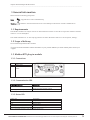
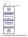
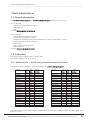
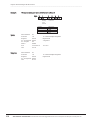
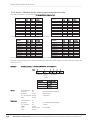
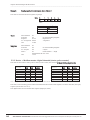
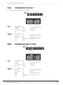
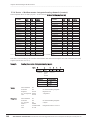
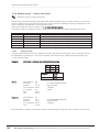
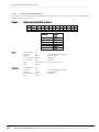
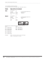
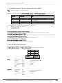
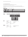
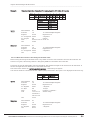
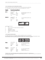
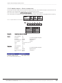
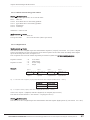
R/09/en/03.14 2210 Operating Instructions Regicont RCD-300 Modbus Slave Advanced Graphic Data Manager Products Solutions ware A, V02.11.xx Operating Instructions Memograph M, RSG40 Advanced Graphic Data Manager Services Graphic Data Manager/Modbus Slave __________________________________________________________________________________ Table of contents: 1 General information ................................................................................................................................ 41 3 3 1.1 Requirements........................................................................................................................................................ 41 3 1.2 Scope of delivery ................................................................................................................................................... 41 3 1.3 Modbus RTU plug-in module .............................................................................................................................. 41 3 1.3.1 Connections ................................................................................................................................................... 41 3 1.3.2 Communication LED ..................................................................................................................................... 41 3 1.3.3 Status LED ..................................................................................................................................................... 41 4 1.3.4 Modbus RTU connector (DB9F) ................................................................................................................... 42 4 1.4 Modbus TCP plug-in module ............................................................................................................................... 42 4 1.4.1 Connections ................................................................................................................................................... 42 4 1.4.2 Network status LED ...................................................................................................................................... 42 5 1.4.3 Status LED ..................................................................................................................................................... 43 5 1.4.4 Link LED ........................................................................................................................................................ 43 5 1.5 Functional description ......................................................................................................................................... 43 5 1.6 Checking whether the Modbus module is present............................................................................................. 43 2 Settings in the Setup ................................................................................................................................ 44 6 8 2.1 Analog channels ................................................................................................................................................... 46 8 2.2 Mathematics channels ......................................................................................................................................... 46 9 2.3 Digital channels .................................................................................................................................................... 47 3 Data transmission .................................................................................................................................... 11 49 3.1 General information ............................................................................................................................................. 49 11 3.2 Addressing ............................................................................................................................................................ 49 11 3.2.1 Modbus master -> Device: analog channels instantaneous value ............................................................. 49 11 3.2.2 Modbus master -> Device: digital input status ........................................................................................... 51 13 3.2.3 Device -> Modbus master: analog inputs instantaneous value ................................................................. 52 14 3.2.4 Device -> Modbus master: maths channels result ...................................................................................... 53 15 3.2.5 Device -> Modbus master: digital channels (status, pulse counter) .......................................................... 54 16 3.2.6 Device -> Modbus master: integrated analog channels (counter) ............................................................ 56 18 3.2.7 Device -> Modbus master: integrated maths channels (counter) ............................................................. 57 19 3.2.8 Modbus master -> Device: batch data ......................................................................................................... 58 20 3.2.8.1 Starting a batch ............................................................................................................................... 58 20 3.2.8.2 Ending a batch ................................................................................................................................ 59 21 3.2.8.3 Setting the batch designation ........................................................................................................ 60 22 3.2.8.4 Setting the batch name .................................................................................................................. 61 23 3.2.8.5 Setting the batch number ............................................................................................................... 62 24 3.2.8.6 Setting the preset counter .............................................................................................................. 63 25 3.2.8.7 Reading out the batch status .......................................................................................................... 64 26 3.2.9 Modbus master -> Device: set relays ........................................................................................................... 65 27 3.2.9.1 Setting relays ...................................................................................................................................... 65 27 3.2.9.2 Reading out the relay status ............................................................................................................. 66 28 3.2.10 Modbus master -> Device: changing the limit values .............................................................................. 67 29 3.2.10.1 Initializing limit value changes ....................................................................................................... 67 29 3.2.10.2 Changing limit values ...................................................................................................................... 68 30 3.2.10.3 Enter the reason for the change in the limit value ....................................................................... 69 31 3.2.10.4 Accepting limit values ..................................................................................................................... 70 32 3.2.10.5 Reading out the communication status ......................................................................................... 71 33 3.2.10.6 Read out limit values ....................................................................................................................... 71 33 3.2.10.7 Tables and definitions ..................................................................................................................... 72 34 3.2.11 Modbus master -> Device: transfer text .................................................................................................... 73 35 3.2.12 Structure of the process values .................................................................................................................. 74 36 3.2.12.1 32-bit floating point number (IEEE-754)...................................................................................... 74 36 3.2.12.2 Off-limit conditions ......................................................................................................................... 74 36 3.2.12.3 Status of the floating point number ............................................................................................... 75 37 3.2.12.4 Digital status .................................................................................................................................... 75 37 4 List of abbreviations/explanation of terms ............................................................................................... 38 76 5 Index ...................................................................................................................................................... 38 76 2 40 ACS-CONTROL-SYSTEM GmbH l Lauterbachstr. 57 l D-84307 Eggenfelden l www.acs-controlsystem.de l [email protected] Graphic Data Manager/Modbus Slave __________________________________________________________________________________ 1 General information Please note the following pictograms: Note: Suggestions for safe commissioning Caution: Failure to observe instructions can cause damage to the device or lead to malfunction! 1.1 Requirements The Modbus module can only be used as of device firmware version V1.02.00 in conjunction with PC software version 1.23.1.0 and higher. The maths channels 9 to 12 are only supported as of device firmware version V1.10.00 Option „Energy“. 1.2 Scope of delivery Device with integrated Modbus module. For technicalinformation information and documentation on your product defined its serial number see For more more technical and documentation on your product defined by itsby serial number please contact your www.endress.com/deviceviewer supplier. 1.3 Modbus RTU plug-in module 1.3.1 Connections 1 2 3 Communication LED Status LED Modbus connector DB9F Tab. 1: View of the rear Modbus RTU device connection 1.3.2 Communication LED Communication LED Off Flashing yellow (data pulse) Description Not online / No power Online and data transfer stopped Data transfer active Tab. 2: Functional description of the communication LED in Modbus RTU 1.3.3 Status LED Status LED Off Green Red Flashing red (1 flash) Flashing red (2 flashes) Description No power or not initialized Initialized, no errors Internal error Transmission or configuration error Diagnosis available Tab. 3: Functional description of the status LED in Modbus RTU 41 ACS-CONTROL-SYSTEM GmbH l Lauterbachstr. 57 l D-84307 Eggenfelden l www.acs-controlsystem.de l [email protected] 3 Graphic Data Manager/Modbus Slave __________________________________________________________________________________ 1.3.4 Modbus RTU connector (DB9F) The Modbus connector is galvanically isolated and supports RS-232 or RS-485 Connections are not assigned in the standard way (Modbus over serial line specification an implementation guide V1.02). Pin Housing 1 2 3 Direction 1 Output Input Signal Functional earth GND 5V PMC 4 5 6 7 8 9 Bidirectional Input OUTPUT Bidirectional B-Line Rx Tx A-Line Tab. 4: Pin assignment of the Modbus RTU connector 1 Description Protective earth Earth (isolated) +5V DC (isolated) Connect to pin 2 for RS-232 functionality. For RS-485 functionality, do not connect. RS-485 B-Line RS-232 Data Receive RS-232 Data Transmit RS-485 A-Line Any current drawn from this pin will affect the total power consumption of the module. 1.4 Modbus TCP plug-in module 1.4.1 Connections 1 2 3 4 Network status LED Status LED Link/Activity Modbus connector RJ45 Tab. 5: View of the rear Modbus TCP device connection 1.4.2 Network status LED Note: A test sequence is displayed when the unit is powered up. Network status LED Off Green Red Flashing red Flashing green Indicates No power or IP address Module active Serious error Data transfer stopped or no connection At first initialization and while waiting for connection Tab. 6: Functional description of the operation mode LED in Modbus TCP 4 42 ACS-CONTROL-SYSTEM GmbH l Lauterbachstr. 57 l D-84307 Eggenfelden l www.acs-controlsystem.de l [email protected] Graphic Data Manager/Modbus Slave __________________________________________________________________________________ 1.4.3 Status LED Status LED Off Green Flashing red Red Indicates No power or not initialized Initialized Initialized, diagnosis available Exception error Tab. 7: Functional description of the status LED in Modbus TCP 1.4.4 Link LED Status LED Off Flashing green Indicates No connection, no activity Activity Tab. 8: Functional description of the link LED in Modbus TCP 1.5 Functional description The Modbus RTU module allows the device to be connected to Modbus RTU, with the functionality of an RTU slave. Baud rates supported in baud: 1200, 2400, 4800, 9600, 19200, 38400, 57600, 115200 The Modbus TCP module allows the device to be connected to Modbus TCP, with the functionality of a TCP slave. The Ethernet connection supports 10/100Mbit, full or half duplex. 1.6 Checking whether the Modbus module is present Under /Main menu/Diagnosis/simulation/Device information/ENP/Hardware, you can use the Bus interface function to check whether a Modbus module is used. The software version and serial number are visible here, and for Modbus TCP, the MAC address also. Fig. 1: Checking whether the Modbus module is present 43 ACS-CONTROL-SYSTEM GmbH l Lauterbachstr. 57 l D-84307 Eggenfelden l www.acs-controlsystem.de l [email protected] 5 Graphic Data Manager/Modbus Slave __________________________________________________________________________________ 2 Settings in the Setup Modbus RTU: A slave address between 1 and 247 is configured under /Setup/System/Modbus (see Fig. 2). Fig. 2: Entering the slave address in Modbus RTU Fig. 3: Entering the baudrate in Modbus RTU Fig. 4: Selecting the parity in Modbus RTU Fig. 5: Selecting the timeout in Modbus RTU 6 44 ACS-CONTROL-SYSTEM GmbH l Lauterbachstr. 57 l D-84307 Eggenfelden l www.acs-controlsystem.de l [email protected] Graphic Data Manager/Modbus Slave __________________________________________________________________________________ Modbus TCP: The IP address is configured under /Setup/System/Modbus (see Fig. 6 to Fig. 8). You can choose between DHCP and manual entry: Fig. 6: Selecting DHCP in Modbus TCP Fig. 7: Automatic IP address assignment in Modbus TCP If the IP is entered manually, IP address, subnetmask and gateway must be entered (see Fig. 8): Fig. 8: Selecting manual entry of IP address in Modbus TCP Fig. 9: Selecting the timeout in Modbus TCP 45 ACS-CONTROL-SYSTEM GmbH l Lauterbachstr. 57 l D-84307 Eggenfelden l www.acs-controlsystem.de l [email protected] 7 Graphic Data Manager/Modbus Slave __________________________________________________________________________________ The IP address assigned using DHCP can be viewed under /Main menu/Diagnosis/Simulation/Device information/ENP. 2.1 Analog channels All analog (40) and digital (14) inputs are enabled and can be used as Modbus inputs even if they are not really available as plug-in cards. Data transfer Modbus master -> Device: Under /Setup/Inputs/Analog inputs/Analog input X, the Signal parameter is set to Modbus. The analog channel configured in this way can be selected for data transfer (see Section 3.2.1). Fig. 10: Setting the analog channel to Modbus Fig. 11: Selecting the desired channel Data transfer, device -> Modbus master Analog inputs 1 to 20 can be read by the Modbus master as described in Section 3.2.1. 2.2 Mathematics channels Data transfer, device -> Modbus master Mathematics channels are optionally available under /Setup/Inputs/Maths. The results can be read by the Modbus master (see Section 3.2.4). 8 46 ACS-CONTROL-SYSTEM GmbH l Lauterbachstr. 57 l D-84307 Eggenfelden l www.acs-controlsystem.de l [email protected] Graphic Data Manager/Modbus Slave __________________________________________________________________________________ 2.3 Digital channels Data transfer, Modbus master -> Device: Under /Setup/Inputs/Digital inputs/Digital input X, the Function parameter is set to Modbus. The digital channel configured in this way can be used for data transfer (see Section 3.2.2). Fig. 12: Setting the digital channel to Modbus The digital status transmitted by the Modbus master has the same functionality in the device as the status of a digital channel really available. Data transfer, device -> Modbus master Control input or on/off event The digital status of the digital channel configured in this way can be read by the Modbus master (see Section 3.2.5). Pulse counter or operating time The counter or the total operating time of the digital channel configured in this way can be read by the Modbus master (see Section 3.2.5). Event+operation time The digital status and counter of the digital channel configured in this way can be read by the Modbus master (see Section 3.2.5). 47 ACS-CONTROL-SYSTEM GmbH l Lauterbachstr. 57 l D-84307 Eggenfelden l www.acs-controlsystem.de l [email protected] 9 Graphic Data Manager/Modbus Slave __________________________________________________________________________________ An overview can be called up via a Web browser (Ethernet option). The IP address to be specified is that of the device and not the Modbus module (TCP). E.g. URL: http://192.168.100.7/fieldbus Fig. 13: Web site of Modbus overview 10 48 ACS-CONTROL-SYSTEM GmbH l Lauterbachstr. 57 l D-84307 Eggenfelden l www.acs-controlsystem.de l [email protected] Graphic Data Manager/Modbus Slave __________________________________________________________________________________ 3 Data transmission 3.1 General information The 03: Read Holding Register and 16: Write Multiple Register functions are supported. You can transfer Analog values (instantaneous values) Digital statuses Text from the Modbus master to the device. You can transfer Analog values (instantaneous values) Integrated analog values (counter) Mathematics channels (result: status, instantaneous value, operating time, counter) Integrated maths channels (counter) Digital status Pulse counter (overall counter) Operating times from the device to the Modbus master. 3.2 Addressing The query/response samples refer to Modbus RTU. The register addresses are all on base 0. 3.2.1 Modbus master -> Device: analog channels instantaneous value The values of analog channels 1-40 must be written via 16 Write Multiple Register. Channel Analog 1 Analog 2 Analog 3 Analog 4 Analog 5 Analog 6 Analog 7 Analog 8 Analog 9 Analog 10 Analog 11 Analog 12 Analog 13 Analog 14 Analog 15 Analog 16 Analog 17 Analog 18 Analog 19 Analog 20 Reg. Dec. 0 3 6 9 12 15 18 21 24 27 30 33 36 39 42 45 48 51 54 57 Reg. Hex. 000 003 006 009 00C 00F 012 015 018 01B 01E 021 024 027 02A 02D 030 033 036 039 Length in bytes 6 6 6 6 6 6 6 6 6 6 6 6 6 6 6 6 6 6 6 6 Channel Analog 21 Analog 22 Analog 23 Analog 24 Analog 25 Analog 26 Analog 27 Analog 28 Analog 29 Analog 30 Analog 31 Analog 32 Analog 33 Analog 34 Analog 35 Analog 36 Analog 37 Analog 38 Analog 39 Analog 40 Reg. Dec. 60 63 66 69 72 75 78 81 84 87 90 93 96 99 102 105 108 111 114 117 Reg. Hex. 03C 03F 042 045 048 04B 04E 051 054 057 05A 05D 060 063 066 069 06C 06F 072 075 Length in bytes 6 6 6 6 6 6 6 6 6 6 6 6 6 6 6 6 6 6 6 6 Tab. 9: Register addresses of the analog inputs, Modbus master -> Device The status of the floating point number transmitted in the 2nd and 3rd register is found in the first register (see Section 3.2.12.3). 49 ACS-CONTROL-SYSTEM GmbH l Lauterbachstr. 57 l D-84307 Eggenfelden l www.acs-controlsystem.de l [email protected] 11 Graphic Data Manager/Modbus Slave __________________________________________________________________________________ Example: Writing to analog 17, value 123.456, slave address 5 Byte 0 00 Register 48 49 50 Query: Response: 12 50 Slave address Function Register No. of registers No. of bytes Status FLP CRC 05 10 00 30 00 03 06 00 80 42 F6 E9 79 93 1D Slave address Function Register No. of registers CRC 05 10 00 30 00 03 81 33 1 80 Status floating point number 2 42 3 F6 4 E9 5 79 Floating point number = 123.456 Value (hex) 0080 42F6 E979 16: Write Multiple Registers Register 48 3 registers 123.456 16: Write Multiple Registers Register 48 ACS-CONTROL-SYSTEM GmbH l Lauterbachstr. 57 l D-84307 Eggenfelden l www.acs-controlsystem.de l [email protected] Graphic Data Manager/Modbus Slave __________________________________________________________________________________ 3.2.2 Modbus master -> Device: digital input status The statuses of analog inputs 1-14 must be written via 16 Write Multiple Register. Channel Digital 1-14 Reg. Dec. 120 Tab. 10: Register addresses of the digital inputs, Modbus master -> Device Reg. Hex. 078 Length in bytes 4 The new statuses of the analog inputs are found in the first register (120). The mask which describes if the status is adopted is found in the second register (121). Example: Setting digital input 8 to High and digital input 9 to Low, slave address 5 Byte 0 Status (Bit 15-8) Byte 1 Status (Bit 7-0) Byte 2 Mask (Bit 15-8) Byte 3 Mask (Bit 7-0) Bit 8 Low Digital 9 Bit 7 High Digital 8 Bit 8 High Digital 9 active Bit 7 High Digital 8 active XX000000 10000000 Register 120 121 Query: Response: 51 Slave address Function Register No. of registers No. of bytes Digital status Mask CRC 05 10 00 78 00 02 04 00 80 01 80 E1 C5 Slave address Function Register No. of registers CRC 05 10 00 78 00 02 C0 55 XX000001 10000000 Value (hex) 0080 0180 16: Write Multiple Registers Register 120 2 registers Digital 8 set to High, Digital 9 set to Low Digital 8 and 9 masked 16: Write Multiple Registers Register 120 ACS-CONTROL-SYSTEM GmbH l Lauterbachstr. 57 l D-84307 Eggenfelden l www.acs-controlsystem.de l [email protected] 13 Graphic Data Manager/Modbus Slave __________________________________________________________________________________ 3.2.3 Device -> Modbus master: analog inputs instantaneous value The analog channels 1-20 are read via 03 Read Holding Register (4x). Channel Reg. Reg. Length Dec. Hex. in bytes Analog 1 256 100 6 Analog 2 259 103 6 Analog 3 262 106 6 Analog 4 265 109 6 Analog 5 268 10C 6 Analog 6 271 10F 6 Analog 7 274 112 6 Analog 8 277 115 6 Analog 9 280 118 6 Analog 10 283 11B 6 Tab. 11: Register addresses of the analog inputs, device -> Modbus master Channel Reg. Dec. 286 289 292 295 298 201 304 307 310 313 Analog 11 Analog 12 Analog 13 Analog 14 Analog 15 Analog 16 Analog 17 Analog 18 Analog 19 Analog 20 Channel Reg. Reg. Length Channel Dec. Hex. in bytes Analog 21 784 310 6 Analog 31 Analog 22 788 314 6 Analog 32 Analog 23 792 318 6 Analog 33 Analog 24 796 31C 6 Analog 34 Analog 25 800 320 6 Analog 35 Analog 26 804 324 6 Analog 36 Analog 27 808 328 6 Analog 37 Analog 28 812 32C 6 Analog 38 Analog 29 816 330 6 Analog 39 Analog 30 820 334 6 Analog 40 Tab. 181a: Advanced register addresses of the analog inputs, device -> Modbus master Reg. Dec. 824 828 832 836 840 844 848 852 856 860 Reg. Hex. 11E 121 124 127 12A 12D 130 133 136 139 Reg. Hex. 338 33C 340 344 348 34C 350 354 358 35C Length in bytes 6 6 6 6 6 6 6 6 6 6 Length in bytes 6 6 6 6 6 6 6 6 6 6 The status of the floating point number transmitted in the 2nd and 3rd register is found in the first register (see Section 3.2.12.3). Example: Reading analog 2 , value 5.016928673, slave address 5 Byte 0 00 1 80 Off-limit conditions Status floating point number Register 259 260 261 14 Query: Slave address Function Register No. of registers CRC 05 03 01 03 00 03 F5 B3 Response: Slave address Function No. of bytes Status FLP CRC 05 03 06 00 80 42 2C 1F BA 4E 59 52 2 42 3 2C 4 1F 5 BA Floating point number = 43.030983 Value (hex) 0080 422C 1FBA 03: Read Holding Register Register 259 3 registers 03: Read Holding Register 6 bytes 43.030983 ACS-CONTROL-SYSTEM GmbH l Lauterbachstr. 57 l D-84307 Eggenfelden l www.acs-controlsystem.de l [email protected] Graphic Data Manager/Modbus Slave __________________________________________________________________________________ 3.2.4 Device -> Modbus master: maths channels result The results of the mathematics channels are read via 03 Read Holding Register (4x). Channel Reg. Dec. 316 319 322 325 328 331 334 337 736 740 744 748 Maths 1 Maths 2 Maths 3 Maths 4 Maths 5 Maths 6 Maths 7 Maths 8 Mathe 9 Mathe 10 Mathe 11 Mathe 12 Reg. Hex. 13C 13F 142 145 148 14B 14E 151 2E0 2E4 2E8 2EC Tab. 12: Register addresses of the mathematics channels, device -> Modbus master Length in bytes 6 6 6 6 6 6 6 6 6 6 6 6 The status of the floating point number transmitted in the 2nd and 3rd register is found in the first register (see Section 3.2.12.3). Example: Reading maths 1 (result instantaneous value), slave address 5 Byte 0 00 1 80 Digital status / Off-limit conditions Status floating point number Register 316 317 318 Query: Slave address Function Register No. of registers CRC 05 03 01 3C 00 03 C5 BF Response: Slave address Function No. of bytes Status FLP CRC 05 03 06 00 80 41 A0 00 00 06 75 53 2 41 3 A0 4 00 5 00 Floating point number = 20.0 Value (hex) 0080 41A0 0000 03: Read Holding Register Register 316 3 registers 03: Read Holding Register 6 bytes 20.0 ACS-CONTROL-SYSTEM GmbH l Lauterbachstr. 57 l D-84307 Eggenfelden l www.acs-controlsystem.de l [email protected] 15 Graphic Data Manager/Modbus Slave __________________________________________________________________________________ Example: Reading maths 1 (result status), slave address 5 The status is found in the first register, high byte. Byte 0 01 1 00 Digital status Register 316 317 318 2 00 3 00 4 00 5 00 Value (hex) 0100 0000 0000 Query: Slave address Function Register No. of registers CRC 05 03 01 3C 00 03 C5 BF 03: Read Holding Register Register 316 3 registers Response: Slave address Function No. of bytes Status 05 03 06 01 00 00 00 00 00 12 64 03: Read Holding Register 6 bytes Result maths 1 = High Not used CRC 3.2.5 Device -> Modbus master: digital channels (status, pulse counter) The statuses and values of the pulse counter (total counter) are read via 03 Read Holding Register (4x). Channel Digital 1 Digital 2 Digital 3 Digital 4 Digital 5 Digital 6 Digital 7 Reg. Dec. 340 343 346 349 352 355 358 Reg. Hex. 154 157 15A 15D 160 163 166 Length in bytes 6 6 6 6 6 6 6 Tab. 13: Register addresses of the digital channels, device -> Modbus master Channel Digital 8 Digital 9 Digital 10 Digital 11 Digital 12 Digital 13 Digital 14 Reg. Dec. 361 364 367 370 373 376 379 Reg. Hex. 169 16C 16F 172 175 178 17B Length in bytes 6 6 6 6 6 6 6 The status of the floating point number transmitted in the 2nd and 3rd register is found in the first (low byte) register (see Section 3.2.12.3). The digital status is found in the first register (high byte, bit 0). 16 54 ACS-CONTROL-SYSTEM GmbH l Lauterbachstr. 57 l D-84307 Eggenfelden l www.acs-controlsystem.de l [email protected] Graphic Data Manager/Modbus Slave __________________________________________________________________________________ Example: Reading digital 2 (status), slave address 5 The status is found in the first register, high byte. Byte 0 01 1 00 Digital status Register 343 344 345 2 00 3 00 4 00 5 00 Value (hex) 0100 0000 0000 Query: Slave address Function Register No. of registers CRC 05 03 01 57 00 03 B4 63 03: Read Holding Register Register 343 3 registers Response: Slave address Function No. of bytes Status 05 03 06 01 00 00 00 00 00 12 64 03: Read Holding Register 6 bytes Result digital = High Not used CRC Example: Reading digital 2 (pulse counter), slave address 5 Byte 0 00 Digital status 1 80 Status floating point number Register 343 344 345 Query: Slave address Function Register No. of registers CRC 05 03 01 57 00 03 B4 63 Response: Slave address Function No. of bytes Status Status FLP CRC 05 03 06 01 80 40 A0 00 00 06 58 55 2 40 3 A0 4 00 5 00 Floating point number = 5.0 Value (hex) 0080 40A0 0000 03: Read Holding Register Register 343 3 registers 03: Read Holding Register 6 bytes Result digital = High Pulse counter to 5.0 ACS-CONTROL-SYSTEM GmbH l Lauterbachstr. 57 l D-84307 Eggenfelden l www.acs-controlsystem.de l [email protected] 17 Graphic Data Manager/Modbus Slave __________________________________________________________________________________ 3.2.6 Device -> Modbus master: integrated analog channels (counter) The integrated values of analog inputs 1-40 are read via 03 Read Holding Register (4x). Channel Analog 1 Analog 2 Analog 3 Analog 4 Analog 5 Analog 6 Analog 7 Analog 8 Analog 9 Analog 10 Analog 11 Analog 12 Analog 13 Analog 14 Analog 15 Analog 16 Analog 17 Analog 18 Analog 19 Analog 20 Reg. Dec. 528 532 536 540 544 548 552 556 560 564 568 572 576 580 584 588 592 596 600 604 Reg. Hex. 210 214 218 21C 220 224 228 22C 230 234 238 23C 240 244 248 24C 250 254 258 25C Length in bytes 6 6 6 6 6 6 6 6 6 6 6 6 6 6 6 6 6 6 6 6 Channel Reg. Dec. 608 612 616 620 624 628 632 636 640 644 648 652 656 660 664 668 672 676 680 684 Analog 21 Analog 22 Analog 23 Analog 24 Analog 25 Analog 26 Analog 27 Analog 28 Analog 29 Analog 30 Analog 31 Analog 32 Analog 33 Analog 34 Analog 35 Analog 36 Analog 37 Analog 38 Analog 39 Analog 40 Tab. 14: Register addresses of the integrated analog inputs, device -> Modbus master Reg. Hex. 260 264 268 26C 270 274 278 27C 280 284 288 28C 290 294 298 29C 2A0 2A4 2A8 2AC Length in bytes 6 6 6 6 6 6 6 6 6 6 6 6 6 6 6 6 6 6 6 6 The status of the floating-point number transmitted in the 2nd and 3rd register is found in the first (low byte) register (see Section 3.2.12.3). Example: Reading the counter of integrated analog input 5 Byte 0 00 1 80 Off-limit conditions Status floating point number Register 544 545 546 18 Query: Slave address Function Register No. of registers CRC 05 03 02 20 00 03 04 3D Response: Slave address Function No. of bytes Status FLP CRC 05 03 06 00 80 43 E8 46 BB F5 C8 56 2 43 3 E8 4 46 5 BB Floating point number = 464.55 Value (hex) 0080 43E8 D417 03: Read Holding Register Register 544 3 registers 03: Read Holding Register 6 bytes Integrated value to 464.55 ACS-CONTROL-SYSTEM GmbH l Lauterbachstr. 57 l D-84307 Eggenfelden l www.acs-controlsystem.de l [email protected] Graphic Data Manager/Modbus Slave __________________________________________________________________________________ 3.2.7 Device -> Modbus master: integrated maths channels (counter) The integrated values of mathematics channels 1-12 are read via 03 Read Holding Register (4x). Channel Reg. Dec. 688 692 696 700 704 708 712 716 720 724 728 732 Maths 1 Maths 2 Maths 3 Maths 4 Maths 5 Maths 6 Maths 7 Maths 8 Mathe 9 Mathe 10 Mathe 11 Mathe 12 Reg. Hex. 2B0 2B4 2B8 2BC 2C0 2C4 2C8 2CC 2D0 2D4 2D8 2DC Length in bytes 6 6 6 6 6 6 6 6 6 6 6 6 Tab. 15: Register addresses of the integrated maths channels, device -> Modbus master The status of the floating-point number transmitted in the 2nd and 3rd register is found in the first (low byte) register (see Section 3.2.12.3). Example: Reading the counter of integrated mathematics channel 1 Byte 0 00 1 80 Off-limit conditions Status floating point number Register 688 689 690 Query: Slave address Function Register No. of registers CRC 05 03 02 B0 00 03 04 10 Response: Slave address Function No. of bytes Status FLP CRC 05 03 06 00 80 45 1D C0 00 C7 61 57 2 45 3 1D 4 C0 5 00 Floating point number = 2524 Value (hex) 0080 451D C000 03: Read Holding Register Register 688 3 registers 03: Read Holding Register 6 bytes Integrated value to 2524 ACS-CONTROL-SYSTEM GmbH l Lauterbachstr. 57 l D-84307 Eggenfelden l www.acs-controlsystem.de l [email protected] 19 Graphic Data Manager/Modbus Slave __________________________________________________________________________________ 3.2.8 Modbus master -> Device: batch data Firmware version V2.00.00 and higher Batches can be started and stopped. The batch name, batch designation, batch number and preset counter can also be configured for stopping the batch. The texts (ASCII) can have a maximum length of 30 characters. If the text is longer than 30 characters it is truncated and saved. The functions and texts must be written using 16 Write Multiple Register. If an uneven number of characters is sent, a blank (0x20) must follow. The blank is ignored in the device. Function 0x01 0x02 0x03 0x04 0x05 0x06 3.2.8.1 Description Start batch Stop batch Batch designation Batch name Batch number Preset counter Data Batch (1 to 4), ID, name Batch (1 to 4), ID, name Batch (1 to 4), text (max 30 characters) Batch (1 to 4), text (max 30 characters) Batch (1 to 4), text (max 30 characters) Batch (1 to 4), text (max 12 characters) Starting a batch If the user administration function is enabled, an ID (max. 8 characters) and a name (max. 20 characters) must be transmitted, separated by a ';'. If an uneven number of characters is sent, a blank (0x20) must follow (see 3.2.8.2 Ending a batch). Example: Start batch 2 (without user administration function) Byte Register 3088 Query: Slave address Function Register No. of registers No. of bytes Data CRC 05 10 0C 10 00 01 02 01 02 D2 51 Response: Slave address Function Register No. of registers CRC 05 10 0C 10 00 01 02 D8 0 func 1 1 no. 2 Value (hex) 0102 16: Write Multiple Register Register 3088 1 register 2 bytes 16: Write Multiple Register Register 3088 1 register The entry "Batch 2 started" is saved in the event list. This message also appears on the screen for a few seconds. 20 58 ACS-CONTROL-SYSTEM GmbH l Lauterbachstr. 57 l D-84307 Eggenfelden l www.acs-controlsystem.de l [email protected] Graphic Data Manager/Modbus Slave __________________________________________________________________________________ 3.2.8.2 Ending a batch If the user administration function is enabled, an ID (max. 8 characters) and a name (max. 20 characters) must be transmitted, separated by a ';'. If an uneven number of characters is sent, a blank (0x20) must follow. Example: End batch 2, user administration function enabled (ID: "IDSPS", Name "RemoteX") Byte 0 func 2 1 no. 2 2 49 'I' 3 44 'D' 4 53 'S' 5 50 'P' 6 53 'S' Register 3088 3089 3090 3091 3092 3093 3094 3095 7 3B ';' 8 52 'R' 9 65 'e' 10 6D 'm' 11 6F 'o' 12 74 't' 13 65 'e' 14 58 'X' 15 20 ‚’ Value (hex) 0202 4944 5350 533B 5265 6D6F 7465 5820 Query: Slave address Function Register No. of registers No. of bytes Data CRC 05 10 16: Write Multiple Register 0C 10 Register 3088 00 08 8 registers 10 16 bytes 02 02 49 44 53 59 53 3B 52 65 6D 6F 74 65 58 20 D3D6 Response: Slave address Function Register No. of registers CRC 05 10 0C 10 00 08 C2 DE 16: Write Multiple Register Register 3088 8 registers The entry "Batch 2 terminated" and "Remote (IDSPS)" is saved in the event list. This message also appears on the screen for a few seconds. 59 ACS-CONTROL-SYSTEM GmbH l Lauterbachstr. 57 l D-84307 Eggenfelden l www.acs-controlsystem.de l [email protected] 21 Graphic Data Manager/Modbus Slave __________________________________________________________________________________ 3.2.8.3 Setting the batch designation Can only be set if the batch has not yet been started. It does not have to be set if it is not required by the device settings (Direct access 16070). Example: Batch designation "Identifier" for batch 2 Byte 0 func 3 1 no. 2 2 49 'I' 3 64 'd' 4 65 'e' Register 3088 3089 3090 3091 3092 3093 22 5 6E 'n' 6 74 't' 7 69 'i' 8 66 'f' 10 65 'e' 11 72 'r' Value (hex) 0302 5964 656E 7469 6669 6572 Query: Slave address Function Register No. of registers No. of bytes Data CRC 05 10 16: Write Multiple Register 0C 10 Register 3088 00 06 6 registers 0B 12 byte 03 02 59 64 65 6E 74 69 66 69 65 72 0E 20 Response: Slave address Function Register No. of registers CRC 05 10 0C 10 00 06 43 1A 60 9 69 'i' 16: Write Multiple Register Register 3088 6 registers ACS-CONTROL-SYSTEM GmbH l Lauterbachstr. 57 l D-84307 Eggenfelden l www.acs-controlsystem.de l [email protected] Graphic Data Manager/Modbus Slave __________________________________________________________________________________ 3.2.8.4 Setting the batch name Can only be set if the batch has not yet been started. It does not have to be set if it is not required by the device settings (Direct access 16071). Example: Batch name "Name" for batch 2 Byte 0 func 4 1 no. 2 Register 3088 3089 3090 2 4E 'N' 3 61 'a' 4 6D 'm' 5 65 'e' Value (hex) 0402 4E61 6D65 Query: Slave address Function Register No. of registers No. of bytes Data CRC 05 10 16: Write Multiple Register 0C 10 Register 3088 00 03 3 registers 06 6 bytes 04 02 4E 61 6D 65 04 C8 Response: Slave address Function Register No. of registers CRC 05 10 0C 10 00 03 83 19 61 16: Write Multiple Register Register 3088 3 registers ACS-CONTROL-SYSTEM GmbH l Lauterbachstr. 57 l D-84307 Eggenfelden l www.acs-controlsystem.de l [email protected] 23 Graphic Data Manager/Modbus Slave __________________________________________________________________________________ 3.2.8.5 Setting the batch number Can only be set if the batch has not yet been started. It does not have to be set if it is not required by the device settings (Direct access 16072). Example: Batch number "Num" for batch 2 Byte 0 func 5 1 no. 2 Register 3088 3089 3090 24 2 4E 'N' 3 75 'u' 4 6D 'm' 5 20 ‚’ Value (hex) 0502 4E75 6D20 Query: Slave address Function Register No. of registers No. of bytes Data CRC 05 10 16: Write Multiple Register 0C 10 Register 3088 00 03 3 registers 06 6 bytes 05 02 4E 75 6D 20 84 EE Response: Slave address Function Register No. of registers CRC 05 10 0C 10 00 03 83 19 62 16: Write Multiple Register Register 3088 3 registers ACS-CONTROL-SYSTEM GmbH l Lauterbachstr. 57 l D-84307 Eggenfelden l www.acs-controlsystem.de l [email protected] Graphic Data Manager/Modbus Slave __________________________________________________________________________________ 3.2.8.6 Setting the preset counter Can only be set if the batch has not yet been started. It does not have to be set if it is not required by the device settings (Direct access 16073). Maximum 12 characters (including '.') Exponential function permitted, e.g. "1.23E-2" Only positive numbers Example: Preset counter to 12.345 for batch 2 Byte 0 func 6 1 no. 2 2 31 '1' Register 3088 3090 3091 3092 3 32 '2' 4 2E '.' 5 33 '3' 6 34 '4' Value (hex) 0602 3132 2E33 3435 Query: Slave address Function Register No. of registers No. of bytes Data CRC 05 10 16: Write Multiple Register 0C 10 Register 3088 00 04 4 registers 08 8 bytes 06 02 31 32 2E 33 34 35 D3 B5 Response: Slave address Function Register No. of registers CRC 05 10 0C 10 00 04 C2 DB 63 7 35 '5' 16: Write Multiple Register Register 3088 4 registers ACS-CONTROL-SYSTEM GmbH l Lauterbachstr. 57 l D-84307 Eggenfelden l www.acs-controlsystem.de l [email protected] 25 Graphic Data Manager/Modbus Slave __________________________________________________________________________________ 3.2.8.7 Reading out the batch status This can be used to read out the status of every batch and the last communication status. Example: Batch 2 started, communication status "OK" Query: Slave address Function Register No. of registers CRC 05 03 0C 10 00 03 06 DA Response: Slave address Function Register No. of bytes Data CRC 05 3 03: Read holding register (4x) 0C 10 Register 3088 6 6 bytes 00 00 00 01 00 00 42 75 Byte 03: Read holding register (4x) Register 3088 3 registers 0 1 Comm. status 0 0 Register 3088 3090 3091 2 Status batch 1 0 3 Status batch 2 1 4 Status batch 3 0 5 Status batch 4 0 Value (hex) 0000 0001 0000 If, for example, a batch number is set even though the batch is already running, the value 0x0003 would be in register 3088. Communication status: 0: OK 1: Not all the necessary data were transmitted (mandatory entries) 2: User responsible not logged on 3: Batch already running 4: Batch not configured 5: Batch controlled via control input 7: Automatic batch number active 9: Error, text contained characters that cannot be displayed, text too long, incorrect batch number Function number out of range Batch status: 0: Batch inactive 1: Batch active 26 64 ACS-CONTROL-SYSTEM GmbH l Lauterbachstr. 57 l D-84307 Eggenfelden l www.acs-controlsystem.de l [email protected] Graphic Data Manager/Modbus Slave __________________________________________________________________________________ 3.2.9 Modbus master -> Device: set relays Firmware version V2.00.00 and higher Relays can be set if they were set to "Remote" in the device settings. 16 Write Multiple Register or 06 Write Single Register can be used for this purpose. 3.2.9.1 Setting relays Relay status: 0: Inactive 1: Active Example: Setting relay 6 to the active state Byte Register 3152 Query: Slave address Function Register No. of registers No. of bytes Data CRC 05 10 0C 50 00 01 02 06 01 96 A0 Response: Slave address Function Register No. of registers CRC 05 10 0C 50 00 01 03 0C 65 0 RelNo 6 1 Status 1 Value (hex) 0601 16: Write Multiple Register Register 3152 1 register 2 bytes 16: Write Multiple Register Register 3152 1 register ACS-CONTROL-SYSTEM GmbH l Lauterbachstr. 57 l D-84307 Eggenfelden l www.acs-controlsystem.de l [email protected] 27 Graphic Data Manager/Modbus Slave __________________________________________________________________________________ 3.2.9.2 Reading out the relay status This reads out the status of every relay. Bit 0 corresponds to relay 1. Example: Relay 1 and relay 6 in an active state Query: Slave address Function Register No. of registers CRC 05 03 0C 50 00 03 86 CF Response: Slave address Function Register No. of bytes Data CRC 05 3 0C 50 2 00 21 89 9C 03: Read holding register (4x) Register 3152 3 registers 03: Read holding register (4x) Register 3152 2 bytes Register 3152 Value (hex) 0021 The relay status is determined from the 2 data bytes as follows: Byte 0: Byte 1: Bit 0 = Status relay 1 Bit 0 = Status relay 9 Bit 1 = Status relay 2 Bit 1 = Status relay 10 Bit 2 = Status relay 3 Bit 2 = Status relay 11 Bit 3 = Status relay 4 Bit 3 = Status relay 12 Bit 4 = Status relay 5 Bit 5 = Status relay 6 Bit 6 = Status relay 7 Bit 7 = Status relay 8 Example: 28 66 "0E07" returns the following status of the relays: Relays 1-3 and relays 10-12 active. ACS-CONTROL-SYSTEM GmbH l Lauterbachstr. 57 l D-84307 Eggenfelden l www.acs-controlsystem.de l [email protected] Graphic Data Manager/Modbus Slave __________________________________________________________________________________ 3.2.10 Modbus master -> Device: changing the limit values Firmware version V2.00.00 and higher Limit values can be set by using 16 Write Multiple Register or 06 Write Single Register for this purpose. Function 0x01 0x02 0x03 Description Initialization Accept limit values Change limit value 0x04 0x05 Read out limit value Enter reason Data Limit value number;value;Time span for gradient;Delay Limit value settings Text containing the reason To change limit values, the following sequence must be observed: 1. Initialize change of limit values 2. Change limit values 3. Accept limit values In versions earlier than firmware version V2.00.04 A subsequent limit value change cannot be initialized until the limit values have been accepted. In versions from firmware version V2.00.04 Any changes since the last initialization can be discarded when a subsequent limit value change is initialized. In versions from firmware version V2.10.00 The delay time can also be configured in addition to the limit value. The activated limit values can be read out. In versions from firmware version V2.10.02 A reason for the change in the limit value can be entered. 3.2.10.1 Initializing limit value changes This prepares the device for changes to the limit values. 16 Write Multiple Register or 06 Write Single Register can be used for this purpose. Byte 0 Func 1 Register 3216 Query: Slave address Function Register No. of registers No. of bytes Data CRC 05 10 0C 90 00 01 02 01 2A 96 A0 Response: Slave address Function Register No. of registers CRC 05 10 0C 90 00 01 03 30 67 1 Fill byte 2A Value (hex) 012A 16: Write Multiple Register Register 3216 1 register 2 bytes 16: Write Multiple Register Register 3216 1 register ACS-CONTROL-SYSTEM GmbH l Lauterbachstr. 57 l D-84307 Eggenfelden l www.acs-controlsystem.de l [email protected] 29 Graphic Data Manager/Modbus Slave __________________________________________________________________________________ 3.2.10.2 Changing limit values Here, a limit value in the device is changed but is not yet accepted. The transmitted values are separated by a semicolon (;). The following structure must be observed: Func limit value [Value];[Span];[Delay type];[Delay] [] means that this value can also be omitted. Likewise, only the values that should be changed need to be transmitted. Examples (see also 3.2.10.7 Tables and definitions): Func 3 3 3 Limit value 1 2 3 Data Meaning 5.22;;1;2 5.34 ;;0;10 Limit value 1 to 5.22, no span, delay in minutes, 2 minutes Limit value 2 to 5.34 Limit value 3, delay to 10 seconds If an uneven number of characters is sent, a blank (0x20) must follow. The blank is ignored in the device. Example: Changing limit value 1 (upper limit value for analog input) to 90.5 Byte 0 Func 3 1 Limit value 1 Register 3216 3217 3218 30 2 39 '9' 3 30 '0' 4 2E '.' 5 35 '5' Value (hex) 0301 3930 2E35 Query: Slave address Function Register No. of registers No. of bytes Data CRC 05 10 16: Write Multiple Register 0C 90 Register 3216 00 03 3 registers 06 6 bytes 03 01 39 30 2E 35 3D FE Response: Slave address Function Register No. of registers CRC 05 10 0C 90 00 03 82 F1 68 16: Write Multiple Register Register 3216 3 registers ACS-CONTROL-SYSTEM GmbH l Lauterbachstr. 57 l D-84307 Eggenfelden l www.acs-controlsystem.de l [email protected] Graphic Data Manager/Modbus Slave __________________________________________________________________________________ Example: Changing limit value 3 (gradient for analog input) to 5.7 within 10 seconds Byte 0 Func 3 1 Limit value 3 Register 3216 3217 3218 3219 2 35 '5' 3 2E '.' 4 37 '7' 5 3B ';' 6 31 '1' 7 30 '0' Value (hex) 0303 352E 373B 3130 Query: Slave address Function Register No. of registers No. of bytes Data CRC 05 10 16: Write Multiple Register 0C 90 Register 3216 00 04 4 registers 08 8 bytes 03 03 35 2E 37 3B 31 30 94 BF Response: Slave address Function Register No. of registers CRC 05 10 0C 90 00 04 C3 33 16: Write Multiple Register Register 3216 4 registers 3.2.10.3 Enter the reason for the change in the limit value Before saving the change in the limit value, it is possible to enter a reason which is saved in the events list. If a reason is not given, the message "Reason: changed by fieldbus" is entered in the events list. Text items (as per the ASCII table) can be transmitted. The maximum length of the text item is 30 characters. If the text is longer than 30 characters it is truncated and saved. The text must be written via 16 Write Multiple Register, 2 characters per register. If an uneven number of characters is sent, a blank (0x20) must follow. The space is not displayed in the event log. Byte Query: Response: 69 Slave address Function Register No. Register No. Byte Data Text CRC 05 10 0C 90 00 07 0E 05 01 52 65 61 73 6F 6E 20 77 68 79 21 20 62 64 Slave address Function Register No. Register CRC 05 10 0C 90 00 07 83 32 0 Func 5 1 Limit value x 10: Write Multiple Register Register 3216 7 Register 14 Byte Function 5, Default 1 "Reason why!" 10: Write Multiple Register Register 3216 7 Register ACS-CONTROL-SYSTEM GmbH l Lauterbachstr. 57 l D-84307 Eggenfelden l www.acs-controlsystem.de l [email protected] 31 Graphic Data Manager/Modbus Slave __________________________________________________________________________________ 3.2.10.4 Accepting limit values Here, the modified limit values are accepted in the device and stored in the device settings. 16 Write Multiple Register or 06 Write Single Register can be used for this purpose. Byte 0 Func 2 Register 3216 32 Query: Slave address Function Register No. of registers No. of bytes Data CRC 05 10 0C 90 00 01 02 02 2A C5 7F Response: Slave address Function Register No. of registers CRC 05 10 0C 90 00 01 03 30 70 1 Fill byte 2A Value (hex) 022A 16: Write Multiple Register Register 3216 1 register 2 bytes 16: Write Multiple Register Register 3216 1 register ACS-CONTROL-SYSTEM GmbH l Lauterbachstr. 57 l D-84307 Eggenfelden l www.acs-controlsystem.de l [email protected] Graphic Data Manager/Modbus Slave __________________________________________________________________________________ 3.2.10.5 Reading out the communication status This can be used to read out the status of the last limit value function performed. As a prerequisite, limit value readout should not be enabled (see 3.2.10.6). Example: Incorrect function addressed Query: Slave address Function Register No. of registers CRC 05 03 0C 90 00 01 86 F3 Response: Slave address Function No. of bytes Data CRC 05 3 2 00 01 88 44 03: Read holding register (4x) Register 3216 1 register 03: Read holding register (4x) 2 bytes Register 3216 Value (hex) 0001 Communication status: 0: OK 1: Incorrect function number or limit value number 2: Missing data 3: Limit value not active 4: Gradient-> two values 5: Function currently not possible 9: Error 3.2.10.6 Read out limit values To activate the function, the number of the first desired limit value is transmitted. By activating this function, reading from Modbus address 3216 no longer returns the communication status. Instead the limit value settings of the limit value in question is returned in 6 registers. Byte 0 Func 4 1 Limit value 1 Query: Slave address Function Register Data CRC 05 06 0C 90 04 01 48 33 06: Write Single Register Register 3216 Function 4, Limit value 1 Response: Slave address Function Register Data CRC 05 06 0C 90 04 01 48 33 06: Write Single Register Register 3216 Function 4, Limit value 1 Afterwards the desired limit value settings (6 registers) are read out from register 3216. If the limit value number transmitted is outside the limit value limits (1-100), the following error is indicated in the communication status: 71 ACS-CONTROL-SYSTEM GmbH l Lauterbachstr. 57 l D-84307 Eggenfelden l www.acs-controlsystem.de l [email protected] 33 Graphic Data Manager/Modbus Slave __________________________________________________________________________________ Query: Slave address Function Register No. Register CRC 05 03 0C 90 00 06 C7 31 Response: Slave address Function No. Bytes Data Data CRC 05 03 03: Read Holding register (4x) 0C 12 Bytes 00 01 Incorrect limit value number 00 00 00 00 00 00 00 00 00 00 93 8F 03: Read Holding register (4x) Register 3216 6 Register Otherwise the process of querying the communication status returns the settings of a limit value (see also 3.2.10.7 Tables and definitions): Response: Slave address Function No. Bytes LV,LVType Value Span Delay type Delay CRC 05 03 0C 01 01 40 B0 00 00 00 00 00 00 00 04 59 9C 03: Read Holding register (4x) 12 Bytes Limit value 1, Lower limit value 5.5 Time span for gradient (not required here) Seconds 4 Seconds After each query, the limit value number is set to the next activated limit value and can be read out with the next query. After the last activated limit value, the system starts again with the first activated limit value. If no limit values are activated, all the data are set to 0 in the response. To deactivate the function, 255 is transmitted as the limit value number or a function not equal to 4 is performed. 3.2.10.7 Tables and definitions LV: Values between 1 and 100 LVType: 0 1 2 3-6 7 8-11 12-15 34 Switched off Lower limit value Upper limit value Evaluation 1-4 Gradient dy/dt Evaluation: limit value statistics, frequency Evaluation: limit value statistics, duration Value: Limit value as floating point number (IEEE754, Big Endian) Span: Time span for gradient (1-60 s) Delay type: Unit of delay time. Delay: 0 Seconds 1 Minutes 2 Hours Delay time in the unit set above (0-999). 72 ACS-CONTROL-SYSTEM GmbH l Lauterbachstr. 57 l D-84307 Eggenfelden l www.acs-controlsystem.de l [email protected] Graphic Data Manager/Modbus Slave __________________________________________________________________________________ 3.2.11 Modbus master -> Device: transfer text Text (as per the ASCII table) can be stored in the device's event log. The maximum length of the text item is 40 characters. If it is longer than 40 characters, it is shortened when stored. The text must be written via 16 Write Multiple Register, 2 characters per register. If an odd number of characters is sent, a space must follow (0x20). The space is not displayed in the event log. Channel Reg. Dec. 3024 Text Reg. Hex. BD0 Tab. 16: Register addresses for the transfer of text, Modbus master -> Device Byte 0 41 ‚A’ 1 42 ‚B’ Register 3024 3025 3026 2 43 ‚C’ 3 44 ‚D’ Length in bytes Max. 40 4 45 ‚E’ 5 20 ‚’ Value (hex) 4142 4344 4520 Example: Generating the text "ABCDE" Query: Slave address Function Register No. of registers No. of bytes Data CRC 05 10 16: Write Multiple Register 0B D0 Register 3024 00 03 3 registers 06 6 bytes 41 42 43 44 45 20 D8 4E Response: Slave address Function Register No. of registers CRC 05 10 0B D0 00 03 82 51 16: Write Multiple Register Register 3024 3 registers Fig. 14: Entry of text in the event log 73 ACS-CONTROL-SYSTEM GmbH l Lauterbachstr. 57 l D-84307 Eggenfelden l www.acs-controlsystem.de l [email protected] 35 Graphic Data Manager/Modbus Slave __________________________________________________________________________________ 3.2.12 Structure of the process values 3.2.12.1 32-bit floating point number (IEEE-754) Octet 0 1 2 3 8 7 7 Sign (E) 2 0 -1 (E) 2 (M) 2 -8 (M) 2 -16 (M) 2 6 6 (E) 2 -2 (M) 2 5 Sign = 0: Positive number 3 2 1 1 (E) 2 -7 (M) 2 -15 (M) 2 -23 (M) 2 Number 1VZ 1 M 2 E 127 Sign = 1: Negative number E = Exponent, M = Mantissa Example: 4 40 F0 00 00 h = 0100 0000 1111 0000 0000 0000 0000 0000 b Value = 10 2129127 1 21 22 23 1 0,5 0,25 0,125 = 1 4 1,875 7,5 = 1 2 Byte 2 0 00 Off-limit conditions 1 80 Status floating point number 2 40 3 F0 4 00 5 00 Floating point number = 7.5 3.2.12.2 Off-limit conditions Device -> Modbus master Here the conditions of the first 8 assigned limit values of the channel are registered. Bit 0: … Bit 7: 1st assigned limit value Bit x = 1: = 0: 8th assigned limit value Limit violation No limit violation Example: If a limit on instantaneous value and a limit value on analysis 1 are assigned to the analog input 1, then the 2 limit value conditions in bit 0 and 1 are indicated in the measured value of analog input 1 (register 256) and the integrated analog input 1 (register 528). Byte 0 02 Off-limit conditions Bit 0 = 0: Bit 1 = 1: 36 74 1 80 Status floating point number 2 40 3 F0 4 00 5 00 Floating point number = 7.5 No limit violation of the 1st assigned limit value; here the limit value is set to the instantaneous value. Limit violation of the 2nd assigned limit value; here the limit value is set to the integrated value. ACS-CONTROL-SYSTEM GmbH l Lauterbachstr. 57 l D-84307 Eggenfelden l www.acs-controlsystem.de l [email protected] Graphic Data Manager/Modbus Slave __________________________________________________________________________________ 3.2.12.3 Status of the floating point number Device -> Modbus master 10H = e.g. cable open circuit, do not use the value 8xH = value OK x.bit 0: lower limit value or decreasing gradient x.bit 1: upper limit value or increasing gradient x.bit 2: underrange x.bit 3: overrange Otherwise = value not OK Modbus master -> Device 80H: value OK Not equal to 80H: do not use the value (cable open circuit) 3.2.12.4 Digital status Modbus master -> Device The statuses of the 14 digital inputs are transmitted in register 2 (4 bytes) (see Section 3.2.2) also. A digital status is described by two bits. The statuses are found in register 120 and the mask, describing which digital input should adopt the status, in register 121. The 2 registers must never be written separately, but rather together via 16 Write Multiple Register. Register 120 bit x Register 121 bit x Example: = 0: = 1: = 0: = 1: "Low" status "High" status Do not adopt Adopt Byte 0 Status (Bit 15-8) Byte 1 Status (Bit 7-0) Byte 2 Mask (Bit 15-8) Byte 3 Mask (Bit 7-0) Bit 8 Low Digital 9 Bit 7 High Digital 8 Bit 8 High Digital 9 active Bit 7 High Digital 8 active XX000000 10000000 XX000001 10000000 Fig. 15: Structure of the 2 registers (4 bytes) transmitted when status is digital (Modbus master -> Device) Register 120 121 Value (hex) 0080 0180 Fig. 16: Register contents (4 bytes) when status is digital (Modbus master -> Device) In this case, only bit 7 (digital 8) and bit 8 (digital 9) are adopted (byte 2 and 3). The statuses for this are bit 8 = low and bit 7 = high (byte 0 and 1). Device -> Modbus master The statuses of the 14 digital inputs are transmitted in the first register (high byte bit 0) (see Section 3.2.5 also). 75 ACS-CONTROL-SYSTEM GmbH l Lauterbachstr. 57 l D-84307 Eggenfelden l www.acs-controlsystem.de l [email protected] 37 Graphic Data Manager/Modbus Slave __________________________________________________________________________________ 4 List of abbreviations/explanation of terms Modbus module: The Modbus RTU or Modbus ETH slave plug-in module that is plugged into the rear of the device Modbus master: function All equipment, such as the PLC and PC plug-in boards, that have a Modbus master 5 Index A Analog channel Analogkanäle Anschlüsse Ausgänge 46 9 4, 5 9 B Baud rate 6, 43 C Connections 41, 42 D Data transmission Datenübertragung Digital status Digitale Zustände 49 11 75 38 E Eingänge 9 F Fließkommazahl 38 76 37 Fließkommazahl Status Floating point number Floating point number status Function Funktionsbeschreibung 38 74 75 43 6 I Inputs 46 L LED, Kommunikation LED, Link LED, Netzwerk-Status LED, operation mode LED, status LED, Status 4 5 5 41, 42 41, 43 4, 5 M Mathematics channel Mathematikkanäle 46 9 O Outputs ACS-CONTROL-SYSTEM GmbH l Lauterbachstr. 57 l D-84307 Eggenfelden l www.acs-controlsystem.de l [email protected] 46 ACS-CONTROL-SYSTEM GmbH l Lauterbachstr. 57 l D-84307 Eggenfelden l www.acs-controlsystem.de l [email protected] 39 Pegel Druck Temperatur Durchfluss Registrierung Visualisierung ¸ Füllstand Messumformer Sensorik USV Wir erwarten Ihren Anruf. ACS-CONTROL-SYSTEM know how mit System Ihr Partner für Messtechnik und Automation ¸ Tel: +49 (0) 8721-9668-0 Fax: +49 (0) 8721-9668-30 [email protected] www.acs-controlsystem.de Stand 032/2013 ACS-CONTROL-SYSTEM GmbH Lauterbachstr. 57 D- 84307 Eggenfelden