1
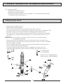
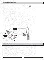
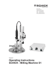
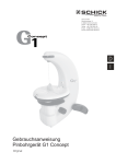
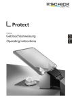
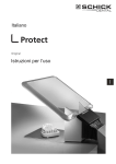
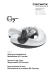
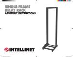
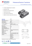
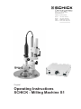
Georg Schick Dental GmbH
Lehenkreuzweg 12
D-88433 Schemmerhofen
Telefon
Telefax
E-Mail
Internet
+49 7356 9500-0
+49 7356 9500-95
[email protected]
www.schick-dental.de
Original
Operating Instructions
SCHICK - Milling Machine S1
SCHICK - Milling Machine S1
Index:
1. Range of Applications
2. General informations
Caution !
!
3. Setting up/operating the unit/exchanging the rotary instruments
4. Replacing the chuck
5. Maintenance and care
- Replacing the carbon brushes
6. Possibel Faults
7. Technical Data
8. Milling Machine S1
9. Accesory
10. Decleration of Conformity
1. Range of Applications
The S1 milling machine is intended for use in dental laboratories. It includes a milling arm which
is easily moved in three dimensions.
This milling machine can be used for the materials usually employed in dental laboratories, such as
waxes, plasters, acrylics, metal etc.
2. General Information
2.1 Ascertain that your mains supply coincides with the data on the rating plate.
2.2 S1 milling machines are not suitable for the following applications:
- in areas where there is a risk of explosion.
2.3 Ensure that all regulatory requirements are observed during use (always wear
protective glasses).
2.4 Under no circumstances should the milling machine be cleaned with compressed
air.
2.5 To retain the precision of the chuck and prolong ist service life, it must always
be fitted with a rotary instrument or the rod supplied with the unit (even when not in use).
2.6 Recycling
WEEE-Reg.-Nr. DE 78620387
Caution: !
- When using rotary instruments, do not exceed the maximum speeds laid down
by their manufacturer.
- repairs and other technical procedures must only be carried out by SCHICK or
other suitable qualified personnel, authorized by SCHICK.
- SCHICK do not guarantee the S1 milling machine should it not have been used
in accordance with the operating instructions.
2
3. Setting up / Operating the unit / exchanging the rotary instruments
3.1 Ascertain that your mains supply coincides with the data on the rating plate.
3.2 Plug the unit into a mains socket.
3.3 Operating the unit (compare page 7)
- switch the main supply on (1)
- place the model table (5) on the platform (6)
- turn the eccentric lever (2) - to lock the model table into position
- move switch (3) to set the milling spindle to clockwise or anti-clockwise rotation
- the control knob (4) is used to select (stepless) the rpm.
3.4 Vertical adjustment of the jointed arm
- grip the jointed arm, unlock the knurled knob (12) and position the arm as required.
Lock the knurled knob (12)
3.5 Securing the jointed arm in position
- the jointed arm can be locked into place as required by locking or unlocking
the clamping levers (9) and (10).
3.6 Working with the vertical rig
- the clamping knob (13) should be unlocked for drilling - by pulling down the motor
a vertical movement of the rig can be carried out. The maximum vertical distance of
the rig is 24mm. Should the clamping knob (13) be locked whilst the rig is
being moved vertically, the milling spindle will be locked at this level. The knurled
knob (7) is a depth stop and can be adjusted individually about the metric
thread around the same drilling depths to repeat.
- the jointed arm can be moved both horizontally and vertically if clamping levers
(9) and (10) are unlocked.
3.7 Tightening the milling spindle of the motor/ exchanging the rotary instrument
! The motor must be switched off before exchanging the rotary instrument !
- turn the chuck lever (8) as far as possible to the right (”open”) and insert the
instrument.
- turn the chuck lever (8) as far as possible to the left (”close”) to tigthen the
instrument into place.
- turning the chuck lever (8) approximately half way to the right (”open”) prevents
the milling spindle rotating yet grips the instrument securely. This position is
intended for gripping a trimming instrument.
3
3. Setting up / Operating the unit / exchanging the rotary instruments
3.8 Surveying spindle
- Unscrew the knurled knob (11)
- Withdraw the milling spindle
- Insert the surveying spindle (17a) or optional (17a) into milling spindle holder
and tighten the knurled knob (11)
4. Replacing the chuck
-
Unscrew the knurled knob (11)
Withdraw the milling spindle
Turn the chuck lever (8) as far as possible to the right (”open”)
Unscrew the union nut (18) completely (if necessary, use a 2,35 mm diameter (20)
tungsten carbide cutter shank) and pull the milling spindle off the motor.
- Use a No. 4115 chuck wrench to jerk the chuck (24) anti-clockwise and unscrew
it completely. If necessary, hold the tongue (21) (on the motor) with a No. 4113
wrench.
Please note: In the chuck is a stroke for short shafts, this could be removed
or replaced as required.
- Grease the chuck (24) lightly and insert it into the shaft. Use the wrenches as
described previously to screw the chuck in clockwise. Screw it in as far as possible
and then tigthen it slightly.
- Prior to inserting the chuck, clean it and the shaft thoroughly as otherwise the
concentricity may be adversely affected.
- Press the milling spindle onto the motor and tighten the union nut (18).
- Insert the milling spindle into the holder and tighten the knurled screw (11)
4114 Ø2,35mm
4117 Ø3,00mm
4115
stroke for pins 4918 Ø2,35mm
stroke for pins 4925 Ø3,00mm
4113
18
4113
21
8
20
11
24
24
4115
4
4115
5. Maintenance and Care
Caution: Do not use compressed air to clean the milling spindle !
!
The chuck should be cleaned and re-greased once in a while, depending on
how dirty it is (refer to section 4).
Replacing the Carbon Brushes
- Unscrew the cover (30) from the motor and pull it back
- Pull on the cord to remove the insert
- Use your fingers to rotate the retaining springs (31) as far as possible in
the direction of the arrow
- Remove the old carbon brushes
- Insert the new brushes, ensuring that the lugs (33) on the carbon brushes
fit into the apertures (34). Do not bend the lugs. The strands (35) of the
brushes must remain exposed.
- Use your fingers to rotate the retaining springs (31) as far as possible over
the brushes.
- Replace the insert with the cord (can only be fitted in one position)
- Screw the cover (30) back into place, ensuring that the cord does not
become twisted
4172 carbon brush
31
35
30
32
33
34
31
6. Possible faults
Should the milling spindle be overloaded or jammed, for savety reasons the unit
switches itself off. To continue operating the unit, switch it “OFF” and “ON” again
(switch 1).
Should the unit overheat, the excess-current cut-out on the back of the controller
is activated. Once the unit has resumed ist normal working temperature, the pin
can be pressed in and the unit will run again at the previously set speed. Should
the pin pop out repeatedly whilst the unit is in operation, the unit is defective.
Should the power decrease of the motor run jerkily, check the carbon brushes.
If necessary, replace them.
5
7. Technical data
Technical daten S1 Junior
Rated voltage:
Rated frequenzy:
Motor torque:
Speedrange:
Concentricity:
230V/ 115V/ 100V
50/60 Hz
3,6Ncm
1.000 - 30.000rpm
<0,015mm
chuck:
Subjet to technical modification
without prior notice
Ø2,35mm series
Ø3,0mm on request
Control unit:
milling machine:
Width:
Height:
Depth:
Weight:
Width:
Height:
Depth:
Weight:
200mm
320mm
225mm
2,5kg
185mm
68mm
180mm
2,5kg
8. SCHICK - Milling machine S1
17b
17a
optional:
12
Measuring Spindle
Art.-Nr.
2250
8
11
10
13
9
7
5
1
6
4
3
2
6
9. Accessory S1
Modeltable
Art.-No.
2407/9
Separator
Art.-No. 2655
Milling tray
Art.-No.
Coordinat table
Art.-No. 2505
Light head for turbine
Art.-No. 2510/1
Adaptor ring
Adjustable angle
Art.-No. 2506
Control for light head
Art.-No. 2480
Holding tray
measuring spindle
Art.-No.2250
light head short
Suction tube
Art.-No. 2510/2
2507
Art.-No.
Diamond tool set
Turbine 1,6 mm (8 pcs.)
Art.-No. 2660
2508
Art.-No.
Art.-No.
2509
2470
Polish set 2,35 mm
(3 pcs.) Art.-No. 2665
Milling set 2,35 mm
(7 pcs) Art.-No. 2530
S1 Wooden Base
Art.-No. 2490
Control unit cpl. Art.No 2409
control box Art.No. 2406
motor with milling spindle complete Art.No. 4100/05
S1 - Ceramic-Milling Set cpl. Art.No. 2650/11
(without S1 Junior and S1 Wooden Base)
turbine Art.No 2640/1
holding clip Art.No. 2245
light head for turbine Art.No 2510/1
control for light head Art.No. 2480
cable for light head Art.No. 2485
suction tube Art.No. 2470
separator Art.No. 2655
model table Art.No 2407/9
diamond tool set for turbine 1,6mm (8pcs.) Art.-No. 2660
polish set 2,35mm (3pcs.) Art.-No. 2665
7
10. Declaration of Conformity
We, GEORG SCHICK DENTAL GmbH
Lehenkreuzweg 12
D-88433 Schemmerhofen
declare herewith, that the product
milling machine S1 2405 und 2409
is in conformity with the following provisions of Directive:
2001/95/EG
2006/42/EG
2006/95/EG
2004/108/EG
Name and adress of
person in charge:
(general product safety)
(machinery directive)
(low voltage directive)
(EMV directive)
Wolfgang Schick
Lehenkreuzweg 12
88433 Schemmerhofen
Schemmerhofen, im April 2010
W. Schick
Geschäftsführer
Georg Schick Dental GmbH
Lehenkreuzweg 12
D-88433 Schemmerhofen
Telefon
Telefax
E-Mail
Internet
08/11 bg
+49 7356 9500-0
+49 7356 9500-95
[email protected]
www.schick-dental.de
D20544
8