1
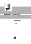
Operating Instructions
Fieldbus Power Supply
System
> 9412/0.-3.0
Fieldbus Power Supply
> 9419/08... bus-Carrier
Contents
1
Contents
1
2
3
4
5
6
7
8
9
10
11
12
13
14
15
16
2
Contents ................................................................................................................2
General Information ...............................................................................................2
General Safety Information ...................................................................................3
Designated Use .....................................................................................................4
Technical Data ......................................................................................................7
Maximum Permissible Ambient Temperatures
(Without Forced Ventilation) ................................................................................11
Main Components ...............................................................................................15
Assembly .............................................................................................................21
Installation ...........................................................................................................24
Commissioning ....................................................................................................31
Diagnosis .............................................................................................................31
Maintenance ........................................................................................................35
Repair work .........................................................................................................35
Transport, Storage and Disposal .........................................................................36
Accessories and Spare Parts .............................................................................36
EC Declaration of Conformity ..............................................................................38
General Information
2.1 Manufacturer
R. STAHL Schaltgeräte GmbH
Am Bahnhof 30
74638 Waldenburg
Germany
Tel:
Fax:
Internet:
+49 7942 943-0
+49 7942 943-4333
www.stahl-ex.com
2.2 Information Regarding the Operating Instructions
ID NO.:
200744 / 941260310030
Publication Number:
2013-08-19·BA00·III·en·03
Hardware version:
from Rev. B
Software version:
from V01-02
We reserve the right to make technical changes without notice.
2.3 Symbols Used
X
Z
X
)
2
Action request:
Describes actions to be carried out by the user.
Reaction sign:
Describes the results or the reactions to the actions taken.
Bullet
Commentary sign:
describes notes and recommendations.
Warning sign:
Danger due to an explosive atmosphere!
Fieldbus Power Supply System
9412/0.-3.0 Fieldbus Power Supply,
9419/08... bus-Carrier
200744 / 941260310030
2013-08-19·BA00·III·en·03
General Safety Information
3
General Safety Information
3.1 Safety Instructions for Assembly and Operating Personnel
The operating instructions contain basic safety instructions which are to be observed
during installation, operation and maintenance. Non-observance will endanger persons,
plant and the environment.
WARNING
Danger due to unauthorised work being performed on the device!
Z Risk of injury and damage to equipment.
X Assembly, installation, commissioning, operation and maintenance must only be
performed by personnel who are both authorised and suitably trained for this purpose.
Before assembly/commissioning:
X Read through the operating instructions.
X Give adequate training to the assembly and operating personnel.
X Ensure that the contents of the operating instructions are fully understood by
the personnel in charge.
X The national installation and assembly regulations (e.g. IEC/EN 60079-14) apply.
When installing the devices:
X When using the device in Zone 2, the device must be built into an enclosure which
corresponds at least to the requirements of the IEC/EN 60079-15.
X The connection components (e.g. cable entries and cable glands, switches, displays,
etc.) of the enclosure must comply with the requirements of IEC/EN 60079-15.
X Make sure that the maximum allowed ambient temperatures for the enclosure are not
exceeded (see chapter "Maximum Allowed Ambient Temperatures (Without Forced
Ventilation)").
When operating the devices:
X Ensure the operating instructions are made available on location at all times.
X Observe safety instructions.
X Observe national safety and accident prevention regulations.
X Only run the device according to its performance data.
X Servicing/maintenance or repair work which are not described in the operating
instructions must not be performed without prior agreement with the manufacturer.
X Any damage may compromise the explosion protection.
X No changes may be made to the devices or their components that compromise
explosion protection.
X Install and use the device only if it is undamaged, dry and clean.
If you have questions:
X Contact the manufacturer.
200744 / 941260310030
2013-08-19·BA00·III·en·03
Fieldbus Power Supply System
9412/0.-3.0 Fieldbus Power Supply,
9419/08... bus-Carrier
3
Designated Use
3.2 Warnings
Warnings are sub-divided in these operating instructions according to the following
scheme:
WARNING
Type and source of the danger!
Z Possible consequences.
X Measures to avoid danger.
They are always identified by the signalling word “WARNING“ and sometimes also have
a symbol which is specific to the danger involved.
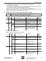
3.3 Conformity to Standards
The component conforms to the following regulations and standards:
X
X
X
X
X
X
X
4
Directive 94/9/EC
Directive 2007/108/EC
IEC/EN 60079-0
IEC/EN 60079-11
IEC/EN 60079-15
IEC/EN 61158-2
FF-831 Foundation Specification: Fieldbus Power Supply Test Specification
Designated Use
WARNING
Only use the device for its intended purpose!
Z Otherwise, the manufacturer’s liability and warranty expire.
X Only use the device under the operating conditions described in the operating
instructions.
X The device must only be used in areas subject to explosion hazards according to
these operating instructions.
The Fieldbus Power Supply is used for the supply of a FOUNDATION™ fieldbus H1
segment. It supplies the connected field devices and the host with energy.
Two Fieldbus Power Supplies each allow a segment to be supplied with power
redundantly or with increased output current (boost operation).
The Fieldbus Power Supply may be installed in hazardous areas of Zone 2 and in the safe
area. When used in Zone 2, the device must be built into an enclosure which corresponds
at least to the requirements of IEC/EN 60079-15.
When a suitable field device coupler (FDC) is used, the trunk may be introduced into
Zone 2 and, when an Ex i fieldbus barrier or an Ex i field device coupler is used, also into
Zone 1.
The Fieldbus Power Supplies 9412/0.-310 and 9412/0.-320 each have an activatable
terminator for standard-compliant termination of a segment end.
4
Fieldbus Power Supply System
9412/0.-3.0 Fieldbus Power Supply,
9419/08... bus-Carrier
200744 / 941260310030
2013-08-19·BA00·III·en·03
Designated Use
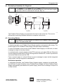
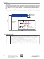
4.1 Exemplary Assembly of a Segment
)
Length segment = Length trunk + ∑ Length spurs ( 1900 m
For information on calculating the allowed segment, trunk and spur lengths,
please refer to IEC 61158-2 and FF AG-181, Rev 3.1.
Fieldbus
Power
Supply
Host
Terminator
Trunk, non-Ex
< 120 m
Trunk, non-Ex
Trunk, non-Ex
<1m
Terminator
Host
redundant
Fieldbus
Power
Supply
redundant
Ex i Field Device
Coupler
Ex i Field Device
Coupler
Ex i / FISCO
Spurs < 120 m
Ex i / FISCO
Spurs < 120 m
...
1
...
Ex i / FISCO
Field Devices
...
...
4/8
1
...
4/8
Ex i / FISCO
Field Devices
14126E02
The Fieldbus Power Supply is connected to the host via the main line. This can be
followed by connecting suitable field device couplers via the trunk.
4.2 Operating Modes
)
Boost operation is only possible by means of the Fieldbus Power Supplies
9412/0.-310 und 9412/0.-320.
Simplex operation
In simplex operation, one Fieldbus Power Supply supplies one segment with energy. The
power supply of the Fieldbus Power Supply may take place redundantly.
In case of overload or short-circuit of the Fieldbus Power Supply or of the trunk, an error
message is output via a relay contact.
In overload mode, normal operation of the FPS continues up to about 540 mA. When the
current output exceeds about 540 mA, the segment is switched off, in order to protect the
connected field devices and the FPS.
From a current output of > about 540 mA, an error message is output via the integrated
relay contact, and the segment is switched off.
Redundant operation
In redundant operation, two Fieldbus Power Supplies supply a segment in parallel with
up to 500 mA. In case of a failure of one Fieldbus Power Supply, the other Fieldbus Power
Supply automatically provides the full power supply, and an error message is output via
a relay contact.
200744 / 941260310030
2010-07-29·BA00·III·en·02
2013-08-19·BA00·III·en·03
Fieldbus Power Supply System
9412/0.-3.0 Fieldbus Power Supply,
9419/08... bus-Carrier
5
Designated Use
Boost operation
In boost operation, two neighbouring Fieldbus Power Supplies permanently supply a
segment in parallel with the twice the current of up to 1 A. This also allows consumers
that have a high current consumption to be connected to a fieldbus
(e.g. Digital I/O Coupler (2-wire) 9413/28). Redundant supply of a segment, in order to
increase availability, is not possible in boost operation.
4.3 Selection of the Fieldbus Power Supply
9412/..-300
00
01
9412/..-310
02
00
01
9412/..-320
02
00
01
02
Operation with Ex ic/nL field devices
(in combination with a suitable Zone 2 FDC)
Uo ( 30.4 V (for Ex ic/nL field devices at Ui > 30.4 V)
x
Uo ( 17.3 V (for Ex ic/nL field devices at Ui > 17.3 V)
x
x
Uo ( 23.7 V (for Ex ic/nL field devices at Ui > 23.7 V)
x
x
x
x
x
x
Installation
DIN rail / pac-Bus
bus-Carrier
x
x
x
x
Terminator can be switched
x
x
x
x
x
x
x
x
x
x
x
x
x
x
x
x
x
x
x
x
x
x
x
x
x
x
Diagnosis
Overload/short-circuit message via relay contact
x
x
x
Fieldbus loss in quality message via relay contact
Display via LED
PWR/ERR
x
x
x
Status Segment/Terminator
x
x
x
x
x
x
x
x
x
x
x
x
x
x
x
Diagnosis of signal quality:
Evaluation via "BAD"/"WARN"/"OK" LED
Diagnosis digitally via PC
Diagnosis via external communication module
(optional)
x
x
x
x
x
x
x
x
x
x
x
x
x
x
x
4.4 Connection of Ex i Field Devices
The output circuit is voltage-limited Ex ic according to IEC/EN 60079-11. Connecting a
downstream current limiter of suitable design (e.g. R. STAHL Zone 2 Field Device
Coupler of series 9411/34 or 9410/34) gives an intrinsically safe current of protection
level Ex ic.
Alternatively, nL field devices according to IEC/EN 60079-15 may also be operated on
this circuit. A label to that effect is required.
4.5 Diagnosis
The external power supply and the general device status will be monitored in all Fieldbus
Power Supplies and displayed via LEDs or a relay contact.
All Fieldbus Power Supplies measure the electrical parameters (Physical Layer) of the
fieldbus, such as current/voltage levels, signal levels, noise, jitter and shielding short
circuit. Depending on design, analysis by PC, integrated LED/relay or online via a
separate diagnosis communication module will take place.
)
6
For the connection options and diagnosis options, see chapter "4.3 Selection
of the Fieldbus Power Supply", "7.3 LEDs and Error Message Contact at the
Fieldbus Power Supply" and "11.2 Diagnosis via PC".
Fieldbus Power Supply System
9412/0.-3.0 Fieldbus Power Supply,
9419/08... bus-Carrier
200744 / 941260310030
2013-08-19·BA00·III·en·03
2010-07-29·BA00·III·en·02
Technical Data
5
Technical Data
Version
9412/0.-3.0
Explosion protection
Gas explosion protection
ATEX
E II 3G Ex nA nC IIC T4 Gc
IECEx
Ex nA nC IIC T4 Gc
Installation
Zone 2, safe area
Certificates
ATEX
BVS 09 ATEX E 099 X
IECEx
IECEx BVS 09.0043X
Power supply
Nominal voltage
24 V DC
Voltage range
18 ... 32 V
9412/00
Electrical Data
9412/01
9412/02
Supply voltage [V]
18
24
32
18
24
32
18
24
32
Current consumption [mA]
970
730
550
560
425
325
760
570
435
Power dissipation [W]
3.21
3.27
3.35
all data at max. output current / output voltage
2.33
2.45
2.65
2.73
2.73
2.97
Indication
LED green "PWR"
Reverse polarity
protection
yes
Galvanic isolation
Fieldbus to power supply
250 V AC eff.
Fieldbus
Specification
IEC 61158-2, FOUNDATION TM fieldbus H1 FF-831
Terminator
integrated, switchable
Segment supply
9412/00
9412/01
9412/02
Output voltage [V DC]
) 28.5
) 15.5
) 21.9
ic voltage limit Uo [V]
30.4
17.3
23.7
Electrical Data
(ic acc. to EN 60079-11:2007)
Output current
Simplex mode
10 ... 500 mA
Redundant mode
10 ... 500 mA (= 2 x 250 mA in redundant mode 2 x 9412)
Boost mode
10 mA ... 1 A (= 2 x 500 mA in parallel operation 2 x 9412)
Overload
500 ... 540 mA
Short-circuit current
( 0 mA (output switched off)
Residual ripple
Corresponds to chapter 22.6.2 of IEC 61158-2
Indication
LED yellow "SEG" (flashes in case of overload and short-circuit)
200744 / 941260310030
2013-08-19·BA00·III·en·03
2010-07-29·BA00·III·en·02
Fieldbus Power Supply System
9412/0.-3.0 Fieldbus Power Supply,
9419/08... bus-Carrier
7
Technical Data
Diagnoses
Supply error
< 18 V
Fault detection
9412/0.-310-11s:
Overload and short circuit
9412/0.-320-11s:
Overload, short circuit and Physical Layer values: trunk voltage/current,
signal level, noise, jitter, unsymmetries
Segment error
Overload: > 500 mA (output active)
Short circuit: > 540 mA (output switched off)
Error message
Relay contact (30 V DC / 100 mA)
Fault indication
9412/0.-310-11s:
LED red "ERR" flashes
9412/0.-320-11s:
LED green "OK" for segment in set quality range
LED yellow "WARN" for segment below set quality range
LED rot "BAD" for segment outside specification
Interface
Electromagnetic compatibility
serial, front side (RS232)
Tested to the following standards and regulations: EN 61326 (IEC/EN 61000-4-1...6 and 11;
EN 55022 class A); NAMUR NE21
Ambient conditions
Ambient temperature
- 20 ... + 70 °C (observe operating instructions)
Storage temperature
- 40 ... + 80 °C
Relative humidity
(no condensation)
< 95 %
MTBF (to SN 29500)
184 years (at 40 °C)
Connection diagram
pac-Bus
D
12537E00
Mechanical Data
Screw terminals
Connection single-wire
- rigid
- flexible
- flexible with cable end sleeves
(without / with plastic cover)
Connection two wires
- rigid
- flexible
- flexible with cable end sleeves
Weight
Mounting type
Installation position
Enclosure Ingress Protection
Terminal Ingress Protection
Enclosure material
Fire protection class (UL 94)
8
Fieldbus Power Supply System
9412/0.-3.0 Fieldbus Power Supply,
9419/08... bus-Carrier
0.2 ... 2.5 mm2
0.2 ... 2.5 mm2
0.25 ... 2.5 mm2
0.2 ... 1 mm2
0.2 ... 1.5 mm2
0.25 ... 1 mm2
approx 0.135 kg
on DIN rail acc. to EN 50022
(NS35/15; NS35/7.5) or on bus-Carrier
Preferably vertical (see operating instructions)
IP30
IP20
PA 6.6
V0
200744 / 941260310030
2013-08-19·BA00·III·en·03
2010-07-29·BA00·III·en·02
Technical Data
Version
9419/08...
Explosion protection
Gas explosion protection
ATEX
E II 3 G Ex nAc nCc II T4
IECEx
Ex nAc nCc II T4
Installation
Zone 2, safe area
Certificates
ATEX
BVS 09 ATEX E 100 X
IECEx
IECEx BVS 09.0042X
Power supply
Voltage range
19 ... 32 V
Reverse polarity
protection
yes
Indication
LED, green
Fault detection
Line fault LF
Contact (35 V /100 mA) closed in good conditions
Contact (35 V /100 mA) closed in good conditions
Ambient conditions
Ambient temperature
- 20 ... + 70 °C (observe operating instructions)
Storage temperature
- 40 ... + 80 °C
Relative humidity
(no condensation)
< 95 %
Screw terminals
Mechanical Data
Connection single-wire
- rigid
- flexible
- flexible with cable end sleeves
(without / with plastic cover)
Connection two wires
- rigid
- flexible
- flexible with cable end sleeves
200744 / 941260310030
2013-08-19·BA00·III·en·03
2010-07-29·BA00·III·en·02
0.2 mm2 ... 2.5 mm2
0.2 mm2 ... 2.5 mm2
0.25 mm2 ... 2.5 mm2
0.2 mm2 ... 1 mm2
0.2 mm2 ... 1.5 mm2
0.25 mm2 ... 1 mm2
Fieldbus Power Supply System
9412/0.-3.0 Fieldbus Power Supply,
9419/08... bus-Carrier
9
Technical Data
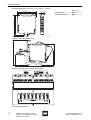
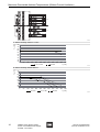
Dimensional Drawings (All Dimensions in mm) - Subject to Alterations
Dimension X
17,6 mm / 0.69 “
Screw terminals
108 mm
Spring-cage terminals
128 mm
122 mm / 4.80 “
114,5 mm / 4.51 “
X
99 mm / 3.90 “
09685E00
130
155
Fieldbus Power Supply 9412/00-3.0-11
156
62
12621E00
Fieldbus Power Supply on bus-Carrier 9419/08.-XX0-..C1
12622E00
bus-Carrier 9419/08.-XX0-..C1
10
Fieldbus Power Supply System
9412/0.-3.0 Fieldbus Power Supply,
9419/08... bus-Carrier
200744 / 941260310030
2013-08-19·BA00·III·en·03
2010-07-29·BA00·III·en·02
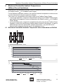
Maximum Permissible Ambient Temperatures (Without Forced Ventilation)
6
Maximum Permissible Ambient Temperatures
(Without Forced Ventilation)
Depending on the installation position, there is a maximum ambient temperature Ta for
the output current Iout of a Fieldbus Power Supply.
For the different installation versions, the maximum ambient temperature on the devices
must be determined using the respective diagram.
The current Iout corresponds to the output current of a Fieldbus Power Supply:
X In the single operation, a segment is supplied with energy by a Fieldbus Power Supply
and therefore the segment current corresponds to the output current Iout of a Fieldbus
Power Supply.
X In the redundant mode, a segment is supplied jointly with power by two Fieldbus Power
Supplies, in which the load current of each module is halved. Accordingly, in order to
determine the maximum permissible ambient temperature, only half the current
demand of the segment must be used in the diagrams for Iout.
6.1 Maximum Permissible Ambient Temperature when Assembled on DIN Rail
A
B
14127E00
Ta in [°C]
A: Horizontal assembly, distance > 17 mm:
75
70
65
60
55
50
45
40
35
30
0
50
100
150
200
250
300
350
15 / 21,4 V DC
400
450
500
28 V DC
550
Io [mA]
14128E00
Ta in [°C]
B: Horizontal assembly, without distance:
75
70
65
60
55
50
45
40
35
30
0
50
100
150
200
15 V DC
200744 / 941260310030
2010-07-29·BA00·III·en·02
2013-08-19·BA00·III·en·03
250
300
21,4 V DC
350
400
450
28 V DC
500
550
Io [mA]
Fieldbus Power Supply System
9412/0.-3.0 Fieldbus Power Supply,
9419/08... bus-Carrier
14129E00
11
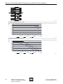
Maximum Permissible Ambient Temperatures (Without Forced Ventilation)
D
C
14130E00
Ta in [°C]
C: Vertical assembly, distance > 17 mm:
75
70
65
60
55
50
45
40
35
30
0
50
100
150
200
15 V DC
250
300
350
21,4 V DC
400
450
500
28 V DC
550
Io [mA]
14131E00
Ta in [°C]
D: Vertical assembly, without distance:
75
70
65
60
55
50
45
40
35
30
0
50
100
150
200
15 V DC
250
300
21,4 V DC
350
400
450
28 V DC
500
550
Io [mA]
14132E00
12
Fieldbus Power Supply System
9412/0.-3.0 Fieldbus Power Supply,
9419/08... bus-Carrier
200744 / 941260310030
2013-08-19·BA00·III·en·03
2010-07-29·BA00·III·en·02
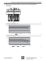
Maximum Permissible Ambient Temperatures (Without Forced Ventilation)
6.2 Maximum Permissible Ambient Temperature when Assembled on
bus-Carrier
A
B
14133E00
Ta in [°C]
A: Horizontal assembly, distance > 17 mm:
75
70
65
60
55
50
45
40
35
30
0
50
100
150
200
250
300
350
400
450
500
15 / 21,4 / 28 V DC
550
Io [mA]
14134E00
Ta in [°C]
B: Horizontal assembly, without distance:
75
70
65
60
55
50
45
40
35
30
0
50
100
150
200
15 V DC
250
300
21,4 V DC
350
400
450
28 V DC
500
550
Io [mA]
14135E00
200744 / 941260310030
2013-08-19·BA00·III·en·03
2010-07-29·BA00·III·en·02
Fieldbus Power Supply System
9412/0.-3.0 Fieldbus Power Supply,
9419/08... bus-Carrier
13
Maximum Permissible Ambient Temperatures (Without Forced Ventilation)
D
C
14136E00
Ta in [°C]
C: Vertical assembly, distance > 17 mm:
75
70
65
60
55
50
45
40
35
30
0
50
100
150
200
250
300
350
15 / 21,4 V DC
400
450
500
28 V DC
550
Io [mA]
14137E00
Ta in [°C]
D: Vertical assembly, without distance:
75
70
65
60
55
50
45
40
35
30
0
50
100
150
200
15 V DC
250
300
21,4 V DC
350
400
450
28 V DC
500
550
Io [mA]
14138E00
14
Fieldbus Power Supply System
9412/0.-3.0 Fieldbus Power Supply,
9419/08... bus-Carrier
200744 / 941260310030
2013-08-19·BA00·III·en·03
2010-07-29·BA00·III·en·02
Main Components
7
Main Components
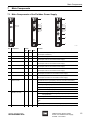
7.1 Main Components of the Fieldbus Power Supply
3
4
1
1
2
3
4
5
6
7
8
2
3
4
5
6
7
8
67
5
4
3
21
89
A
B
C
D
E
0F
9
SIGNAL QUALITY
BAD
WARN
OK
9412
9412
9412
/00-300-10
/00-310-11
/00-320-11
11
10
11
12574E00
No.
Component
9412/0.-
Function
300
310
320
1
Terminals
-
x
x
Connection for the power supply and the redundancy circuit
(see chapter "Installation").
2
Diagnosis interface
-
x
x
To read out the diagnosis information via a PC
3
LED green "PWR"
x
x
x
Indicates the status of the power supply
(see chapter "LEDs on the Fieldbus Power Supply")
4
LED "ERR", red
x
x
x
Indicates the status of the device
(see chapter "LEDs on the Fieldbus Power Supply")
5
LED "TERM", yellow
-
x
x
Indicates the status of the internal terminator
(see chapter "LEDs on the Fieldbus Power Supply")
6
LED "SEG", yellow
-
x
x
Indicates the status of the device
(see chapter "LEDs on the Fieldbus Power Supply")
7
DIP switch "TERM"
-
x
x
Switches the internal terminator on or off
(see chapter "DIP Switch on the Fieldbus Power Supply")
8
DIP switch "BOOST"
-
x
x
Switches the parallel mode to double the output power on or off
(see chapter "DIP Switch on the Fieldbus Power Supply")
9
"Signal Quality Level"
selector switch
-
-
x
Setting the nominal value (Signal Quality Level) of the segment.
The indication of the signal quality is done as a function of this setting.
10
11
LEDs "BAD",
"WARN" and "OK"
Terminals
200744 / 941260310030
2010-07-29·BA00·III·en·02
2013-08-19·BA00·III·en·03
-
-
-
x
x
x
0
no diagnosis of the signal quality
1
poor signal quality
2, 3,...
increasing signal quality
F
maximum signal quality
Indication of the signal quality of the segment
BAD
Signal a lot worse than originally set signal quality level or outside
the specification
WARN
Signal worse than originally set signal quality level
WARN
(flashes)
no communication detected
OK
Signal corresponds to selected signal quality level
Connection for the trunk and the host (see chapter "Installation")
Fieldbus Power Supply System
9412/0.-3.0 Fieldbus Power Supply,
9419/08... bus-Carrier
15
Main Components
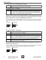
7.2 DIP Switches on the Fieldbus Power Supply
)
For an overview of the LEDs on the Fieldbus Power Supply, see chapter
"Main Components of the Fieldbus Power Supply".
DIP switch "TERM" - Terminator
)
)
The internal terminator is active on delivery
In the redundant or boost operation of two Fieldbus Power Supplies, the
terminator in both Fieldbus Power Supplies must have the same setting
(ON or OFF). If the settings differ, the LEDs "ERR" and "TERM" will flash
(see chapter "LEDs on the Fieldbus Power Supply").
The terminator is used to terminate a segment. Two terminators are required for one
segment. One terminator is located at the beginning (e.g. in the Fieldbus Power Supply)
and the other is located at the end of a segment (e.g. an integrated terminator in the Field
Device Coupler 9411 or an external Fieldbus Terminator 9418).
If the internal terminator is active, the LED "TERM" is lit. If the internal terminator is active
in the redundant mode, the LED "TERM" is lit on both devices but only one terminator is
active.
activated
deactivated
12597E00
12599E00
DIP switch "BOOST" - Boost mode
)
)
)
)
In parallel operation with deactivated Boost mode, the power is supplied
redundantly (see chapter "Installation").
The Boost mode is inactive on delivery.
Due to the considerably higher segment current in the Boost mode
(up to 1 A), higher voltage drops occur in the lines or in the components.
X Before activation of the Boost mode, check the segment using the Fieldbus
Wizard of R. STAHL (see chapter "Accessories and Spare Parts").
In the Boost mode, no redundant power supply and in the redundant mode,
no current increase can take place.
The Boost mode allows parallel operation of two Field Power Supplies for the permanent
increase of the possible output current. This function is possible when mounted on a
DIN rail and on a bus-Carrier.
The two Fieldbus Power Supplies supply the energy for the segment together. The supply
current is distributed in equal parts on both Fieldbus Power Supplies.
activated
deactivated
12596E00
16
12598E00
Fieldbus Power Supply System
9412/0.-3.0 Fieldbus Power Supply,
9419/08... bus-Carrier
200744 / 941260310030
2013-08-19·BA00·III·en·03
2010-07-29·BA00·III·en·02
Main Components
X Install the data connection between two Fieldbus Power Supplies
(see chapter "Installation").
X Before activation of the Boost mode, check the segment using the Fieldbus Wizard of
R. STAHL (see chapter "Accessories and Spare Parts").
X Set the DIP switch "BOOST" in both Fieldbus Power Supplies to ON.
If the Boost setting on the two Fieldbus Power Supplies is different, the red LED "ERR"
flashes, and a message is output via the relay contact.
7.3 LEDs and Fault Contacts on the Fieldbus Power Supply
)
For an overview of the LEDs on the Fieldbus Power Supply, see chapter
"Main Components of the Fieldbus Power Supply".
Status indication with 9412/0.-300, 9412/0.-310 and 9412/0.-320
LED
Colour
Status
Description/Cause of fault
Troubleshooting
LED
"PWR"
green
On
External power supply available
--
Off
Power supply failure
Check the power supply
x
Reverse polarity of the power supply
Establish correct connection of the
power supply
x
On
Internal device fault
Have the device replaced by the
manufacturer
x
flashes
(not with
9412/0.300)
Boost mode is set for single operation
Connect a second Fieldbus Power
Supply or deactivate the Boost mode
x
Setting of the DIP switch "BOOST" or
"TERM" are not identical in the Boost or
redundant mode
Make sure that the setting of the DIP
switch "BOOST" or "TERM" in the
Boost or redundant operation is
identical on both Fieldbus Power
Supplies
x
LED
"ERR"
red
Message
Relay contact
9412/0.-310 and 9412/0.-320
Status indication via LEDs and relay contact
LED
Colour
Status
Description/Cause of fault
LED
"SEG"
yellow
On
Normal operation of the segment
--
Off
Segment is powered up
Wait until the segment has been
powered up
flashing
Segment current is outside the
specification
Only allowed for a limited time period
Check the current consumption of the
segment
Eliminate the short-circuit
Disconnect the field devices,
if necessary
x
flashes
quickly
An overload or a short-circuit has
occurred, the output is off
Check the segment
Disconnect the field devices,
if necessary
x
On
Internal terminator is on
To switch off, see chapter "DIP
switches on the Fieldbus Power
Supply"
Off
Internal terminator is off
To switch on, see chapter "DIP
switches on the Fieldbus Power
Supply"
flashing
Setting of the DIP switch "TERM" on both
Fieldbus Power Supplies differs in the
redundant or boost operation
Make sure that the setting of the DIP
switch "TERM" in the redundant or
Boost operation is identical on both
Fieldbus Power Supplies.
LED
"TERM"
yellow
200744 / 941260310030
2013-08-19·BA00·III·en·03
2010-07-29·BA00·III·en·02
Troubleshooting
Fieldbus Power Supply System
9412/0.-3.0 Fieldbus Power Supply,
9419/08... bus-Carrier
Message
Relay
contact
x
17
Main Components
9412/0.-320
The signal quality of the segment is indicated via the three diagnosis LEDs "BAD",
"WARN" and "OK" (see also chapter "Diagnosis on the Advanced Fieldbus Power
Supply 9412-0.-320“). The following statuses are indicated:
"BAD"
LED
"WARN"
LED
"OK"
LED
Signal quality of the segment
❍
❍
●
corresponds to signal quality nominal value
❍
●
●
drops one level below nominal value
❍
●
❍
exceeds nominal value by two levels
●
●
❍
drops three levels below nominal value
x
●
❍
❍
drops four or more levels below nominal value or is far outside the
IEC specification
x
)
)
Message via
relay contact
Alarm messages due to poor quality of the bus signal can have the following
reasons:
• Minimum requirements of the signal level, noise or jitter value are not met
• Communication level on the bus too high (e.g. due to missing terminator)
• Shielding short-circuit
When the "WARN" LED is flashing, the Fieldbus Power Supply will not detect
any communication on the fieldbus.
Function of the relay contacts
As soon as the message "X" is output, the module contact Diag/9(-) (open in normal
operation) will be closed and the pac-Bus collective message contact "Diag" (closed in
normal operation) opened.
pac-bus
24 V
Diag - +
98 Diag
7+
24 V DC
Host
S 15
- 14
+ 13
5 Red. 2
4 Red. 1
Trunk
S 12
- 11
+ 10
3 S
2 1 +
bus-carrier
12573E00
)
18
For the diagnosis options via PC, see chapter "Diagnosis via PC".
Fieldbus Power Supply System
9412/0.-3.0 Fieldbus Power Supply,
9419/08... bus-Carrier
200744 / 941260310030
2013-08-19·BA00·III·en·03
2010-07-29·BA00·III·en·02
Main Components
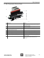
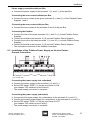
7.4 Main Components of the bus-Carrier
12575E00
No.
Component
Function
1
bus-Carrier
Support for 8 Fieldbus Power Supplies, possibilities to
connect the external power supply, the trunks, the hosts and
the diagnosis messages
2
pac-Bus
Transmission of the external power supply to the individual
Fieldbus Power Supplies
3
Fieldbus Power Supply
Supply of host and trunk with energy
4
Terminals (version equipped with terminals and/or plug
connections depending on the type)
Connection for host and trunk
5
Strain relief and shield bus
Support for the shield of the segment supply line
6
Terminals PE shield
Connection to the equipotential bonding
7
LED power supply
Is lit if the power is correctly supplied
8
Terminals for external power supply
Connection of the simple or redundant power supply
9
Terminals for diagnosis and power supply error
Connection for the indication of a power supply failure and
diagnosis messages
10
DIP switch "PWR" and "DIA"
Activation or deactivation of the redundant power supply or
the error contact (see chapter "DIP Switch on the
bus-Carrier")
200744 / 941260310030
2010-07-29·BA00·III·en·02
2013-08-19·BA00·III·en·03
Fieldbus Power Supply System
9412/0.-3.0 Fieldbus Power Supply,
9419/08... bus-Carrier
19
Main Components
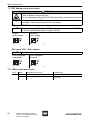
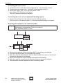
7.5 DIP Switch on the bus-Carrier
WARNING
Explosion hazard!
Z Risk of death or severe injuries!
X It is not allowed to change the DIP switches in Zone 2 while power is active!
)
For an overview of the DIP switches on the bus-Carrier,
see chapter "Main Components of the bus-Carrier".
DIP switch "PWR" - Redundant power supply
)
Redundant supply of the I/O modules is only possible with carrier 9419/08R.
On delivery the redundant power supply is active.
simple
power supply
redundant
power supply
12595E00
12592E00
DIP switch "DIA" - Error contact
)
On delivery the error contact is active.
Error messages
suppressed
Error messages
activated
12594E00
12593E00
7.6 LEDs on the bus-Carrier
20
Colour
Status
Description/Cause of fault
Troubleshooting
Green
On
Power supply available
--
Off
Power supply failure
Check the
power supply
Fieldbus Power Supply System
9412/0.-3.0 Fieldbus Power Supply,
9419/08... bus-Carrier
200744 / 941260310030
2010-07-29·BA00·III·en·02
2013-08-19·BA00·III·en·03
Assembly
8
Assembly
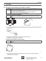
8.1 Assembly of the Fieldbus Power Supply on DIN rail
)
)
Installation on the DIN rail is not possible with type 9412/0.-300!
For simple power supply connection, the Fieldbus Power Supply can be
mounted on a DIN rail with pac-Bus
The components for the pac-Bus must be ordered separately
(see chapter "Spare parts and Accessories").
Assembly of the pac-Bus (optional)
)
A maximum of 8 pac-Bus elements can be connected for a 24 V power
supply.
07391E00
07392E00
X Connect the desired number of pac-Bus elements, place them on the DIN rail and pivot
them onto it.
10264E00
X Assemble the terminal set at the beginning and at the end.
Z Assembly of the pac-Bus is complete.
Assembly of the Fieldbus Power Supplies
)
When pivoting the device onto the DIN rail, make sure that it does not get
jammed.
06885E00
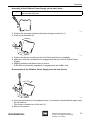
X Insert device onto DIN rail and carefully pivot it onto the rail until the base bolt
completely locks into place.
200744 / 941260310030
2010-07-29·BA00·III·en·02
2013-08-19·BA00·III·en·03
Fieldbus Power Supply System
9412/0.-3.0 Fieldbus Power Supply,
9419/08... bus-Carrier
21
Assembly
Disassembly of the Fieldbus Power Supplies
06881E00
X Pull out the base bolt (1) somewhat using a screwdriver.
X Pivot the device off the DIN rail.
8.2 Assembly of the Fieldbus Power Supply on a bus-Carrier
)
The bus-Carrier can be installed on a mounting plate or on a DIN rail
according to EN 50022 type NS35/7.5 or NS35/15.
Assembly of the bus-Carrier on a mounting plate
08037E00
X Fasten the device with 2 screws on the mounting plate (installation dimensions are
indicated on the dimensional drawing).
Assembly of the bus-Carrier on a DIN rail
12623E00
X Place the device on the DIN rail and pivot it onto the rail.
22
Fieldbus Power Supply System
9412/0.-3.0 Fieldbus Power Supply,
9419/08... bus-Carrier
200744 / 941260310030
2013-08-19·BA00·III·en·03
2010-07-29·BA00·III·en·02
Assembly
Assembly of the Fieldbus Power Supply on the bus-Carrier
)
Before assembly of the Fieldbus Power Supply, all terminals on the base bolt
side must be removed.
06883E00
X Position the screwdriver behind the black and green terminal (1).
X Push out all terminals (2).
06887E00
X Position the device correctly on the bus-Carrier and pivot it completely.
X Make sure that the red detent lever engages with the slot of the Fieldbus Power
Supply.
X Slightly press the red detent lever to close it.
Z If the device is correctly assembled, it engages with an audible click.
Disassembly of the Fieldbus Power Supply from the bus-Carrier
06884E00
X Insert the screwdriver in the red detent lever (1) and swivel the detent lever open using
the screwdriver.
Z The device is pushed out of the slot (2).
X Remove the device.
200744 / 941260310030
2010-07-29·BA00·III·en·02
2013-08-19·BA00·III·en·03
Fieldbus Power Supply System
9412/0.-3.0 Fieldbus Power Supply,
9419/08... bus-Carrier
23
Installation
9
Installation
WARNING
Incorrectly installed components!
Z Explosion protection cannot be guaranteed any more if the components
are incorrectly mounted in Zone 2.
X Carry out the installation in strict accordance with the instructions and
national safety and accident prevention regulations
(e.g. IEC/EN 60079-14).
WARNING
Explosion hazard!
Z Risk of death or severe injuries!
X It is not allowed to work on the power supply in Zone 2 while power is
active!
9.1 Assembly of the Fieldbus Power Supply in the Simplex Mode on the DIN rail
with and without pac-Bus.
)
Installation on the DIN rail is not possible with type 9412/0.-300!
pac-bus
24 V
Diag - +
98 Diag
7+
24 V DC
Host
S 15
- 14
+ 13
5 Red. 2
4 Red. 1
Trunk
S 12
- 11
+ 10
3 S
2 1 +
bus-carrier
12573E00
Type 9412/0.-310-11
Power Supply connection without pac-Bus
X Connect the power supply to the green terminals 7 (+) and 9 (-) of the Fieldbus Power
Supply.
Power supply connection with pac-Bus
X Connect the power supply to the terminals 1 (+) and 2 (-) of the pac-Bus 9194/50-01
(see chapter "Accessories and Spare Parts").
Connecting the error contact without pac-Bus
X Connect the error contact to the green terminals 8 (+) and 9 (-) of the Fieldbus Power
Supply.
Connecting the error contact with pac-Bus
X Connect the error contact to the terminals 3 and 4 of the pac-Bus 9194/50-01
(see chapter "Accessories and Spare Parts").
24
Fieldbus Power Supply System
9412/0.-3.0 Fieldbus Power Supply,
9419/08... bus-Carrier
200744 / 941260310030
2010-07-29·BA00·III·en·02
2013-08-19·BA00·III·en·03
Installation
Connecting the fieldbus
)
X
X
X
X
Z
The shielding line is through-connected from the trunk to the host via the
Fieldbus Power Supply.
Connect the host to the black terminals 14 (-) and 13 (+).
Connect the shield of the host cable to the terminal 15 (S).
Connect the trunk to the black terminals 11 (-) and 10 (+).
Connect the shield of the trunk cable to the terminals 12 (S).
The fieldbus connection is complete.
)
The connections Red.1 and Red.2 must not be used in the Simplex mode
(see chapter "Installation of Fieldbus Power Supply in redundant operation or
Boost operation on a DIN rail with and without pac-Bus".
200744 / 941260310030
2010-07-29·BA00·III·en·02
2013-08-19·BA00·III·en·03
Fieldbus Power Supply System
9412/0.-3.0 Fieldbus Power Supply,
9419/08... bus-Carrier
25
Installation
9.2 Installation of a Fieldbus Power Supply in Redundant Operation or Boost
Operation on a DIN rail with or without pac-Bus
)
)
Boost or redundant operation is only possible by means of types 9412/0.-310
or 9412/0.-320.
The wiring of the trunk and host connections in redundant operation can be
carried out via external terminals or by connecting two conductors to a
terminal near the Fieldbus Power Supply. For the maximum connection
cross-sections, please refer to chapter "Technical Data".
12581E00
Type 9412/0.-310 or 9412/0.-320
Adjustment of the DIP switches
X Make sure before installation that the settings of the "TERM" and "BOOST"
DIP switches on both Fieldbus Power Supplies are identical
(see chapter "DIP Switches on the Fieldbus Power Supply").
Connecting the data communication
X Connect the terminals 4 (Red. 1) and 5 (Red. 2) of the Fieldbus Power Supply 1 to the
terminals 4 (Red. 1) and 5 (Red. 2) of the Fieldbus Power Supply 2.
Z The redundant connection has been established.
Power Supply connection without pac-Bus
X Connect the power supply to the green terminals 7 (+) and 9 (-) of the Fieldbus Power
Supplies 1 and 2.
26
Fieldbus Power Supply System
9412/0.-3.0 Fieldbus Power Supply,
9419/08... bus-Carrier
200744 / 941260310030
2010-07-29·BA00·III·en·02
2013-08-19·BA00·III·en·03
Installation
Power supply connection with pac-Bus
X Connect the power supply to the terminals 1 (+) and 2 (-) of the pac-Bus.
Connecting the error contact without pac-Bus
X Connect the error contact to the green terminals 8 (+) and 9 (-) of the Fieldbus Power
Supplies 1 and 2.
Connecting the error contact with pac-Bus
X Connect the error contact to the terminals 3 and 4 of the pac-Bus.
Connecting the fieldbus
X Connect the host to the black terminals 14 (-) and 13 (+) of both Fieldbus Power
Supplies.
X Connect the shield to the terminal 15 (S) on both Fieldbus Power Supplies.
X Connect the trunk to the black terminals 11 (-) and 10 (+) on both Fieldbus Power
Supplies.
X Connect the shield to the terminal 12 (S) on both Fieldbus Power Supplies.
Z The redundant connection of the fieldbus is complete.
9.3 Installation of the Fieldbus Power Supply on the bus-Carrier General Connection
14141E00
Type 9419/08F-XX0-....
Connecting the power supply (not redundant)
X Connect the power supply to the terminals 2 (+) and 3 (-).
X Set the DIP switch "PWR" (11) on the bus-Carrier to ON
(see chapter "DIP switches on bus-Carrier").
Z The power supply connection is complete.
Connecting the power supply (redundant)
X Connect the first power supply for a redundancy to the terminals 2 (+) and 3 (-).
X Connect the second power supply for a redundancy to the terminals 4 (+) and 5 (-).
X Set the DIP switch "PWR" (11) on the bus-Carrier to OFF
(see chapter "DIP switch on bus-Carrier").
Z The power supply connection is complete.
200744 / 941260310030
2013-08-19·BA00·III·en·03
2010-07-29·BA00·III·en·02
Fieldbus Power Supply System
9412/0.-3.0 Fieldbus Power Supply,
9419/08... bus-Carrier
27
Installation
Connecting the error contact
X Connect the error contact "PF Power supply failure" to the terminals 7 and 8.
X Connect the error contact "Dia" "Line fault" to the terminals 9 and 10.
X Set the DIP switch "Dia" (12) on the bus-Carrier to OFF
(see chapter "DIP Switch on bus-Carrier").
Z The error contact connection is complete.
Connecting the carrier to the equipotential bonding (option)
X Connect the terminal (6) of the shield bus to the earthing network.
Z The connection of the shield busbar (1) to the equipotential bonding is complete.
Removing the insulation of the connecting cable
)
The traction relief and shielding of the fieldbus connecting cable are
established by clamping them under the shield bus
(max. tightening torque: 0.7 Nm).
12578E00
X Remove the insulation of the connecting cable (1) according to the drawing.
X Turn down the bare shield (2) according to the drawing.
X Make sure that the cable diameter with the shield turned down does not exceed the
dimensions indicated on the drawing.
X Remove the insulation of the conductors according to the drawing.
X Make sure that the conductor is not damaged when removing the insulation.
X This procedure must be repeated for other connecting cables.
28
Fieldbus Power Supply System
9412/0.-3.0 Fieldbus Power Supply,
9419/08... bus-Carrier
200744 / 941260310030
2010-07-29·BA00·III·en·02
2013-08-19·BA00·III·en·03
Installation
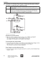
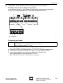
9.4 Installation of the Fieldbus Power Supply on the bus-Carrier Fieldbus Connection for Simplex Operation
In the Simplex operation, each Fieldbus Power Supply supplies one segment with
energy. Up to eight segments can be connected to each bus-Carrier.
5
12577E00
Type 9419/08F-XX0-....
Connecting the fieldbus
)
X
X
X
X
Z
The traction relief and shielding of the fieldbus connecting cable are
established by clamping them under the shield bus
(max. tightening torque: 0.7 Nm).
Removing the insulation of the connecting cable (see chapter “Installation of the Fieldbus Power Supply on the bus-Carrier - General Connection“)
Connect the host to the black terminals 1 (+) and 2 (-) for each fieldbus circuit.
Connect the trunk to the terminals 3 (+) and 4 (-) for each fieldbus circuit.
Connect the shields of the connecting cables to the shield bus (5)
(max. tightening torque of the terminals: 0.7 Nm).
The redundant connection of the fieldbus is complete.
200744 / 941260310030
2013-08-19·BA00·III·en·03
2010-07-29·BA00·III·en·02
Fieldbus Power Supply System
9412/0.-3.0 Fieldbus Power Supply,
9419/08... bus-Carrier
29
Installation
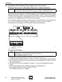
9.5 Installation of the Fieldbus Power Supply on the bus-Carrier Fieldbus Connection for Redundant Operation or Boost Operation
)
The redundant and Boost operation of the Fieldbus Power Supplies on the
bus-Carriers is only possible if bus-Carriers of type 9419/08R are used.
In the redundant operation, two neighbouring Fieldbus Power Supplies ensure the
redundant supply of a segment. In the Boost operation, two neighbouring Fieldbus Power
Supplies ensure the supply of a segment with the double current. It is therefore possible
to connect four segments in each operating mode. They are internally connected in the
bus-Carrier. An additional external wiring is not necessary.
The connecting cables must ony be connected on a terminal block for each segment or
for every two Fieldbus Power Supplies. Optionally, the host can be connected
redundantly by connecting it to the terminals of both terminal blocks.
5
14142E00
Type 9419/08R-XX0-..C1
Connecting the fieldbus
)
X
X
X
X
X
Z
30
The traction relief and shielding of the fieldbus connecting cable are
established by clamping them under the shield bus
(max. tightening torque: 0.7 Nm).
Removing the insulation of the connecting cable (see chapter “Installation of the
Fieldbus Power Supply on the bus-Carrier - General Connection“)
Connect the host to the terminals 1 (+) and 2 (-) of one of the assigned terminal blocks.
For redundant connection, connect the host also to the terminals 1 (+) and 2 (-) of the
other terminal block.
Connect the trunk to the terminals 3 (+) and 4 (-) of one of the assigned terminal
blocks.
Connect the shields of the connecting cables to the shield bus (5)
(max. tightening torque of the terminals: 0.7 Nm).
The fieldbus connection is complete.
Fieldbus Power Supply System
9412/0.-3.0 Fieldbus Power Supply,
9419/08... bus-Carrier
200744 / 941260310030
2010-07-29·BA00·III·en·02
2013-08-19·BA00·III·en·03
Commissioning
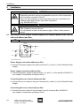
10 Commissioning
Before commissioning, make sure that
X the device has been installed according to regulations in the correct slot,
X the device is not damaged,
X the cables have been connected properly.
11 Diagnosis
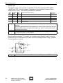
11.1 Definitions of Terms
)
See also IEC 61158-2 or NAMUR NE 123.
Minimum signal level
The minimum voltage level is 450 mV. Low signal levels may occur when the attenuation
of the cable is too high or the segment was over-terminated.
Maximum signal level
The maximum signal level is 1250 mV. High signal levels may occur when the segment
was under-terminated.
Noise / interference levels
Noise is caused by the superposition of undesired voltage levels > 50 mV on the useful
signal. It is caused by the coupling of electromagnetic fields to the fieldbus, for example
due to switching operations, frequency converters, etc.
Critical is the so-called inband noise. Low- or high-frequency noise has no significant
effect on the signal quality.
Jitter
Jitter is the displacement with time of a digital signal from the transmission cycle. Jitter is
caused by cable attenuation (e.g. resulting from increased line or contact resistances) or
over-/undertermination.
Jitter is one of the most important parametes for establishing the quality of a fieldbus
communication.
200744 / 941260310030
2013-08-19·BA00·III·en·03
2010-07-29·BA00·III·en·02
Fieldbus Power Supply System
9412/0.-3.0 Fieldbus Power Supply,
9419/08... bus-Carrier
31
Diagnosis
Symmetry
Here symmetry denotes the voltage-symmetrical power supply, relative to the reference
potential (earth). Deviations give an indication of the quality of the shielding. In industrial
use, values of up to 20 % can be expected, in which the line length plays an important
role.
Values of approx. +/- 100% indicate a short circuit between the line (+ or -) and the shield.
Signal Level
0,75 – 1,0 V SS
Voltage
Fieldbus Signal
Noise
Power Supply
9 – 32 V DC
< 3,2 u s
–
l
Jitter
Ideal Signal
Measured Signal
Time
14139T02
11.2 Diagnosis via PC
)
32
For detailed diagnosis, the Fieldbus Power Supplies 9412/0.-310 and
9412/0.-320 can be connected to a PC using the connecting cable of the
parameterisation set 9199/20-02.
Communication between the Fieldbus Power Supply and the PC is
established via the "HyperTerminal" software component.
This component is part of the standard installation of the Microsoft Windows
XP operating systems (or its predecessors). For newer versions of the
Microsoft Windows operating system, it must be installed additionally.
Fieldbus Power Supply System
9412/0.-3.0 Fieldbus Power Supply,
9419/08... bus-Carrier
200744 / 941260310030
2013-08-19·BA00·III·en·03
2010-07-29·BA00·III·en·02
Diagnosis
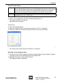
HyperTerminal setup
)
)
The configuration file "9412-Advanced Diagnose.ht" can be downloaded from
http://www.stahl.de/produkte-und-systeme/feldbustechnik.html. After clicking
this file, the HyperTerminal will be automatically configured and opened.
Alternatively, the HyperTerminal connection can also be set manually.
As standard, the connection between the Fieldbus Power Supply and the PC
is established via the "COM1" port.
Standard:
X Click on the configuration file "9412-Advanced Diagnose.ht".
Z The HyperTerminal is configured.
Z HyperTerminal is opened.
Alternatively:
X Open the HyperTerminal.
X Set up the HyperTerminal connection manually via "File > Properties".
X Make sure that the connection settings of the port used are as follows:
14140T02
Z The setup of the HyperTerminal connection is complete.
Reading out the diagnosis data
X Connect the PC and the diagnosis interface of the Fieldbus Power Supply using the
connecting cable of the parameterisation set 9199/20-02.
X Establish connection to the HyperTerminal
Z The diagnosis data is displayed.
200744 / 941260310030
2010-07-29·BA00·III·en·02
2013-08-19·BA00·III·en·03
Fieldbus Power Supply System
9412/0.-3.0 Fieldbus Power Supply,
9419/08... bus-Carrier
33
Diagnosis
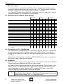
11.3 Diagnosos at the Advanced Fieldbus Power Supply Series 9412/0.-320
)
The signal quality of the connected segment is indicated as a function of the
set value via the "BAD", "WARN" and "OK" LEDs.
To this end, first the signal quality of the segment is established, and the
desired value is set. If the signal quality drops below the set value, this is
indicated by the LEDs.
Determining the signal quality of the connected segment
)
The communication signal of the connected fieldbus devices is permanently
monitored as soon as they are supplied with power from the Fieldbus Power
Supply and the set quality level is > 0.
X Using a screwdriver, set the "Signal Quality Level" selector switch to "1".
Z The "OK" LED is lit.
)
When the "WARN" LED is flashing, no communication will take place on the
segment.
If the "WARN" LED and/or "ERR" LED is lit, the quality of the bus signal is
already extremely poor. Normal bus operation is not recommended under
these circumstances.
X Rotate selector switch clockwise until only the "OK" LED is lit.
Z The signal quality of the connected segment corresponds to the quality level selected
at the selector switch.
)
"BAD"
LED
"WARN"
LED
"OK"
LED
Signal quality of the segment
❍
❍
●
corresponds to signal quality nominal value
❍
●
●
drops one level below nominal value
❍
●
❍
exceeds nominal value by two levels
●
●
❍
drops three levels below nominal value
x
●
❍
❍
drops four or more levels below nominal value or is far outside the IEC specification
x
)
34
To obtain an IEC-compliant warning message ("ERR" LED and message via
relay contact when the level drops below the minimum IEC values from
IEC 61158-2), the adjustable quality level must be at least 4.
If the established quality level is < 4, we recommend checking the segment
via the diagnosis interface (see chapter "Diagnosis via PC") or using a
fieldbus test device.
Message via
relay contact
Should the bus quality deteriorate with time (e.g. by adding further field
devices), this is reported by the yellow "WARN" LED or the red "ERR" LED.
By changing the "Quality Level" setting at the selector switch, the new value
can be set as new nominal value, as a result of which the green "OK" LED is
lit again. The quality level should still be at least 4.
Fieldbus Power Supply System
9412/0.-3.0 Fieldbus Power Supply,
9419/08... bus-Carrier
200744 / 941260310030
2013-08-19·BA00·III·en·03
2010-07-29·BA00·III·en·02
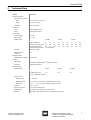
Maintenance
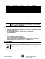
Achieved measured values:
Quality level
Min. signal level
Noise Level
Jitter
Signal quality
1
) 220 mV
( 85 mV
( 3.5 ms
poor
2
) 230 mV
( 75 mV
( 3.2 ms
IEC minimum requirement
3
) 260 mV
( 65 mV
( 2.9 ms
good
4
) 290 mV
( 55 mV
( 2.7 ms
good
5
) 330 mV
( 50 mV
( 2.5 ms
good
6
) 370 mV
( 45 mV
( 2.3 ms
good
7
) 410 mV
( 40 mV
( 2.1 ms
good
8
) 450 mV
( 35 mV
( 1.9 ms
excellent
9
) 500 mV
( 30 mV
( 1.7 ms
excellent
10 (A)
) 550 mV
( 25 mV
( 1.5 ms
excellent
11 (B)
) 600 mV
( 20 mV
( 1.3 ms
excellent
0
12 (C)
) 650 mV
( 16 mV
( 1.1 ms
excellent
13 (D)
) 700 mV
( 13 mV
( 0.9 ms
excellent
14 (E)
) 750 mV
( 10 mV
( 0,7 ms
excellent
15 (F)
) 800 mV
( 7 mV
( 0.5 ms
excellent
)
Although permanent operation of the segment at the quality level "1" (poor) is
possible, it is not recommended, since any deterioration of bus quality can
result in the failure of the segment!
12 Maintenance
X Consult the relevant national regulations (e.g. IEC/EN 60079-17) to determine the type
and extent of inspections.
X Plan the intervals such that any expected defects in the equipment
are detected promptly.
The following inspections have to be carried out during maintenance work:
X
X
X
X
Check if the cables are clamped properly.
Check the device for signs of visible damage.
Compliance with the permitted temperatures in accordance with IEC/EN 60079-0.
Make sure that the device is used according to its designated use.
13 Repair work
WARNUNG
Danger due to improper maintenance/repairs
Z Explosion protection is not guaranteed any longer.
X Repair work to the device must only be performed by R. STAHL.
X Repair work is only to be performed by the manufacturer.
X No changes to the equipment are permitted.
X The equipment must be returned to the manufacturer for repair.
200744 / 941260310030
2013-08-19·BA00·III·en·03
2010-07-29·BA00·III·en·02
Fieldbus Power Supply System
9412/0.-3.0 Fieldbus Power Supply,
9419/08... bus-Carrier
35
Transport, Storage and Disposal
14 Transport, Storage and Disposal
Transport
X Shock-free in its original carton, do not drop, handle carefully.
Storage
X Store in a dry place in its original packaging
X Permitted temperature range for storage in original packaging: - 40 °C ... + 80 °C
Disposal
X Ensure environmentally friendly disposal of all components according to the legal
regulations.
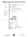
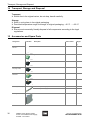
15 Accessories and Spare Parts
Designation
Illustration
Description
Order number
Weight
180 labels
160640
0.001
green
112817
0.001
black
112816
0.001
black
113005
0.001
Green
112825
0.005
black
112824
0.005
NS 35 / 15 (meter length)
103714
1.410
NS 35 / 7.5 (meter length)
103707
0.349
for connection of unused cables
9191/20-00-00
0.060
kg
Labelling sheet
DIN A4
09900E00
Screw terminals
07099E00
07093E00
Screw terminals with
test plug socket
07108E00
Spring-cage
terminals
07094E00
07100E00
DIN rail (EN 50022)
07104E00
Dummy module
07091E00
36
Fieldbus Power Supply System
9412/0.-3.0 Fieldbus Power Supply,
9419/08... bus-Carrier
200744 / 941260310030
2013-08-19·BA00·III·en·03
2010-07-29·BA00·III·en·02
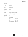
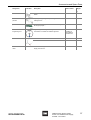
Accessories and Spare Parts
Designation
Illustration
Description
Order number
Weight
kg
End fixture
e. g. Phoenix, E/ME, TBUS NS 35 GY, CLIPFIX 35 or
similar
10271E00
Terminal set for
pac-Bus
5-pole, (set beginning + end) with bridge for fault
message chain
9194/50-01
0.008
Wiring of power supply and collective error message for
device group ISpac
9194/31-17
0.004
Engineering tool for segment design of Fieldbus
Foundation or Profibus PA Fieldbus segments
Download
available at
www.fieldbussolutions.info
Fieldbus Terminator "Ex m"
9418/01-201-10
0.080
Fieldbus Terminator "Ex i"
9418/02-201-10
0.080
to read out the diagnosis data from the Fieldbus Power
Supply 9412 to a PC
9418/20-02
0.080
10264E00
pac-Bus
09885E00
Feldbus Wizard
Engineering Tool
Engineering
Tool
07376E00
Terminator
06501E00
Parameterisation
cable
200744 / 941260310030
2010-07-29·BA00·III·en·02
2013-08-19·BA00·III·en·03
Fieldbus Power Supply System
9412/0.-3.0 Fieldbus Power Supply,
9419/08... bus-Carrier
37
EC Declaration of Conformity
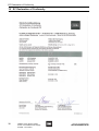
16 EC Declaration of Conformity
38
Fieldbus Power Supply System
9412/0.-3.0 Fieldbus Power Supply,
9419/08... bus-Carrier
200744 / 941260310030
2010-07-29·BA00·III·en·02
2013-08-19·BA00·III·en·03
EC Declaration of Conformity
200744 / 941260310030
2013-08-19·BA00·III·en·03
2010-07-29·BA00·III·en·02
Fieldbus Power Supply System
9412/0.-3.0 Fieldbus Power Supply,
9419/08... bus-Carrier
39
200744 / 941260310030
2013-08-19·BA00·III·en·03
2010-07-29·BA00·III·en·02