1
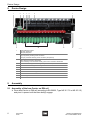
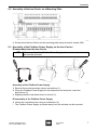
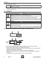
Operating Instructions bus-Carrier > 9419 Contents 1 Contents 1 2 3 4 5 6 7 8 9 10 11 12 2 Contents ................................................................................................................2 General Information ...............................................................................................2 General Safety Instructions ...................................................................................3 Conformity to Standards ........................................................................................3 Intended Field of Application .................................................................................4 Technical Data ......................................................................................................4 Transport, Storage and Disposal ...........................................................................5 Device Design .......................................................................................................6 Assembly ...............................................................................................................6 Installation .............................................................................................................8 Maintenance ........................................................................................................11 EC Declaration Of Conformity .............................................................................12 General Information 2.1 Manufacturer R. STAHL Schaltgeräte GmbH Am Bahnhof 30 74638 Waldenburg Germany Tel: Fax: Internet: +49 7942 943-0 +49 7942 943-4333 www.stahl-ex.com 2.2 Operating Instructions Information ID-No.: Publication Code: Subject to alterations. 2 bus-Carrier 9419 200780 / 941960310010 2011-12-05·BA00·III·en·01 200780 / 941960310010 2011-12-05·BA00·III·en·01 General Safety Instructions 3 General Safety Instructions The devices must be used only for the permitted purpose. Incorrect or impermissible use or non-compliance with these instructions invalidates our warranty provision. Any alterations and modifications to the device impairing its explosion protection are not permitted. Use the device only if it is undamaged and clean. WARNING Installation, maintenance, overhaul and repair may only be carried out by appropriately authorised and trained personnel. Observe the following information during installation and operation: National and local safety regulations National and local accident prevention regulations National and local assembly and installation regulations (e.g. IEC/EN 60079-14) Generally recognized technical regulations Safety instructions in these operating instructions Any damage can invalidate the explosion protection Operate the device according to its performance data only. Servicing/maintenance work or repairs which are not described in the operating instructions must not be performed without prior consultation of the manufacturer. Do not use the device outdoors without a suitable enclosure When using the device in Zone 2, the device must be built into an enclosure which corresponds at least to the requirements of IEC/EN 60079-15. When operating the device in hazardous areas, connection work on the bus-Carrier is not permitted! The bus-Carrier contains components that may become damaged by electrostatic discharges. Before working on the bus-Carrier, make sure to discharge yourself on metallic components or put on an ESD wrist strap! When intrinsically safe (ic) segments are connected to the bus-Carrier, the provided "ic cover" must be mounted, to ensure the required distance between the connection terminals of the auxiliary power and of the segments. Only intrinsically safe (ic) or non-intrinsically safe segments may be operated simultaneously on the bus-Carrier. A mixed assembly is not permitted! The maximum permissible ambient temperature depends on the number and operating modes of the Fieldbus Power Supplies used and of the installation position of the bus-Carrier. For more information, see operating instructions of the Fieldbus Power Supplies Series 9412. If you have questions: Contact the manufacturer. 4 Conformity to Standards The relevant standards are listed in the EC Declaration of Conformity or IECEx Certificate of Conformity. These documents are available for download in the download area on the internet page www.stahl-ex.com. 200780 / 941960310010 2011-12-05·BA00·III·en·01 bus-Carrier 9419 3 Intended Field of Application 5 Intended Field of Application WARNING Use the device in accordance with its designated use only! Otherwise, the manufacturer’s liability and warranty will expire. The device may only be used according to the operating conditions described in these operating instructions. The device must be used in areas subject to explosion hazards only according to these operating instructions. The bus-Carrier is electrical equipment with degree of protection Ex nA, approved for use in hazardous areas of Zone 2 or in the safe area. The bus-Carrier is used for single connection of fieldbus segments to the Fieldbus Power Supply Module 9412. The bus-Carrier supplies the Fieldbus Power Supply Module with auxiliary power (single or redundant) and reports line faults and auxiliary power failure via signalling contacts. The diagnosis communication module Type 9415 (optional) allows diagnosis information of the fieldbus segments connected to the bus-Carrier or Fieldbus Power Supplies to be collected and transmitted to the control system via one of the segments or via a separate diagnosis segment. With the Fieldbus Power Supply Type 9412/0.-3.0-1. inserted, the output circuit is designed voltage-limited according to the protection level Ex ic IIC. Connecting a downstream current limiter of suitable design, e.g., field device coupler Type 9410/34, gives an intrinsically safe electric circuit of protection level Ex ic. The following bus-Carriers are currently available: X 9419/08F-XX1-...: single power supply of 8 fieldbus segments X 9419/04R-XX1-...: redundant power supply of 4 fieldbus segments X 9419/08R-XX1-...: redundant power supply of 8 fieldbus segments 6 Technical Data Explosion protection Europe (ATEX) Gas Global (IECEx) Gas Certificates and Approvals Certificates Further parameters Installation 4 bus-Carrier 9419 BVS 09 ATEX E 100 X E II 3 G Ex nA nC IIC T4 Gc IECEx BVS 09.0042X Ex nA nC IIC T4 Gc ATEX, IECEx Zone 2, safe area 200780 / 941960310010 2011-12-05·BA00·III·en·01 Transport, Storage and Disposal Electrical data Power supply Nominal voltage UN Voltage range Residual ripple within voltage range Redundant supply Reverse polarity protection Indication Electromagnetic compatibility Fault detection Power Fail (pri / red) Diagnosis Ambient Conditions Ambient temperature Storage temperature Relative humidity (no condensation) Mechanical data Connection Trunk Host / red. host DCM Shield Connection cross-section Assembly Installation position Degree of protection Terminals Enclosure material Fire protection class (UL-94) 7 24 V DC 19 ... 32 V ( 3.6 VSS yes, diode-decoupled yes LED, green "pri", "red" Tested under the following standards and regulations: EN 61326-1 Use in industrial environment; NAMUR NE 21 Contact "PF" (35 V /100 mA) closed in good conditions Contact "Dia" (35 V /100 mA) closed in good conditions -20 ... +70 °C for further information, see operating instructions for Type 9412 - 40 °C ... + 80 °C < 95 % to the terminals of the bus-Carrier or of the Fieldbus Power Supplies to the terminals of the bus-Carrier or of the Fieldbus Power Supplies via ribbon cable using plug connectors via integrated shield bar with strain relief Screw terminals Connection single-wire 0.2 mm2 ... 2.5 mm2 - rigid 0.2 mm2 ... 2.5 mm2 - flexible - flexible with cable end sleeves 0.25 mm2 ... 2.5 mm2 (without / with plastic cover) Connection two wires 0.2 mm2 ... 1 mm2 - rigid 0.2 mm2 ... 1.5 mm2 - flexible 0.25 mm2 ... 1 mm2 - flexible with cable end sleeves for further information, see operating instructions for Type 9412 on DIN rail (NS35/15, NS35/7.5) or mounting plate (4 x screw M6) horizontal or vertical IP00 IP20 PA 6.6 V0 Transport, Storage and Disposal Transport Shock-free in its original carton, do not drop, handle carefully. Storage Store in a dry place in its original packaging Disposal Ensure environmentally friendly disposal of all components according to the legal regulations. 200780 / 941960310010 2011-12-05·BA00·III·en·01 bus-Carrier 9419 5 Device Design 8 Device Design 1 3 2 4 5 6 9 8 9 7 10 1 Fault message contacts PF (5/6): Power Fail Dia (7/8): diagnosis 2 Auxiliary power connection pri (1/2): primary auxiliary power connection red (3/4): redundant auxiliary power connection (use optional) 3 DIP switch Dia: diagnosis activated / deactivated red: monitoring of the redundant auxiliary power source activated / deactivated 4 Indication of auxiliary power source (primary and redundant) 5 Connection terminals segment 1 ... segments 4 / 8 6 Shield bus 7 Earth connection 8 Slot for Fieldbus Power Supply 9412 9 Base bolt 10 Slot for diagnosis communication module 9415 11 DCM connection 11 14713E00 Assembly 9.1 Assembly of the bus-Carrier on DIN rail Place bus-Carrier on DIN rail (according to EN 50022, Type NS 35 / 7.5 or NS 35 / 15) and pivot it upward until the base bolt(s) engage. 6 bus-Carrier 9419 200780 / 941960310010 2011-12-05·BA00·III·en·01 Assembly 9.2 Assembly of the bus-Carrier on a Mounting Plate 14744E00 Screw down the bus-Carrier on the mounting plate using at least 4 screws (M5). 9.3 Assembly of the Fieldbus Power Supply on the bus-Carrier / Disassembly from the bus-Carrier Before assembly of the Fieldbus Power Supply, all terminals on the base bolt side must be removed. 3 4 1 2 5 14745E00 Assembly of the Fieldbus Power Supply Remove the screw terminals using a screwdriver (1). Place the Fieldbus Power Supply on the respective slot and pivot it onto the bus-Carrier (2). Slightly press the red detent lever to close it (3). Disassembly of the Fieldbus Power Supply Unlock the red detent lever using a screwdriver (4). The Fieldbus Power Supply is pivoted away from the slot and can be removed. 200780 / 941960310010 2011-12-05·BA00·III·en·01 bus-Carrier 9419 7 Installation 9.4 Mounting the ic Cover The ic cover must be mounted before the auxiliary power and error message cables are connected. Place the ic cover over the connection terminals for the auxiliary power connection and fasten it using the rivet. 10 Installation WARNING Danger due to live parts! Explosion protection is not guaranteed any longer. In hazardous areas, connection work on the connection terminals and attaching/removing the connection terminals are not permitted! Before carrying out work on the connection terminals, the fieldbus and the auxiliary power source of the bus-Carrier must be disconnected from the supply. WARNING Incorrectly installed components! Explosion protection cannot be guaranteed any more if the components are installed incorrectly. Carry out the installation in strict accordance with the instructions and national safety and accident prevention regulations (e.g. IEC/EN 60079-14). 10.1 Removing the Insulation of the Fieldbus Connection Cable 12578E00 Remove the insulation of the connection cable (1) according to the drawing. Turn down the bare shield (2) according to the drawing. Make sure that the cable diameter with the shield turned down does not exceed the dimensions indicated on the drawing. Remove the insulation of the conductors according to the drawing. Make sure that the shield or the conductors are not damaged when removing the insulation. This procedure must be repeated for other connection cables. 8 bus-Carrier 9419 200780 / 941960310010 2011-12-05·BA00·III·en·01 Installation 10.2 Connection of the Fieldbus Segments The strain relief and shield of the fieldbus connection cables are established by clamping them under the shield bus (max. tightening torque: 0.7 Nm). 9419/08F-XX1-...: Removing the insulation of the connection cable (see chapter "Removing the insulation of the fieldbus connection cable") Connect the host to the terminals "Host +" and "Host -" for each fieldbus circuit. Connect the trunk to the terminals "Trunk +" and "Trunk -" for each fieldbus circuit. Connect the shields of the connection cables to the shield bus (max. tightening torque of the terminals: 0.7 Nm). The fieldbus connection is complete. 9419/04R-XX1-...: Removing the insulation of the connection cable (see chapter "Removing the insulation of the fieldbus connection cable") Connect the host to the terminals "Host A +" and "Host A -" for each fieldbus circuit. Connect the redundant host to the terminals "Host B +" and "Host B -" for each fieldbus circuit. Connect the trunk to the terminals "Trunk A +" and "Trunk A -" for each fieldbus circuit. Optionally, the FF H1 fieldbus of a DCM can be connected to the second trunk connection (terminals "Trunk B +" and "Trunk B -"). The terminals of trunk A and trunk B are connected internally to one another. Connect the shields of the connection cables to the shield bus (max. tightening torque of the terminals: 0.7 Nm). The redundant connection of the fieldbus is complete. 9419/08R-XX1-...: Removing the insulation of the connection cable (see chapter "Removing the insulation of the fieldbus connection cable") Connect the host to the terminals "Host A +" and "Host A -" for each fieldbus circuit. Connect the redundant host to the terminals "Host B +" and "Host B -" for each fieldbus circuit. Connect the trunk to the terminals "Trunk +" and "Trunk -" for each fieldbus circuit. Connect the shields of the connection cables to the shield bus (max. tightening torque of the terminals: 0.7 Nm). The redundant connection of the fieldbus is complete. 10.3 Connection of the Auxiliary Power The auxilary power source of the bus-Carrier can be single or redundant. With a single auxiliary power source, the "RED" DIP switch must be set to "OFF", otherwise the redundant auxiliary power source will be reported missing. For the position of the terminals, see chapter 8. Connect the auxiliary power to the terminals "1 +" and "2 -" of the bus-Carrier (single). If required, connect the redundant auxiliary power to the terminals "3 +" and "4 -" of the bus-Carrier. Set the "RED" DIP switch to the "OFF" position (single auxiliary power source) or "ON" position (redundant auxiliary power source). 200780 / 941960310010 2011-12-05·BA00·III·en·01 bus-Carrier 9419 9 Installation 10.4 Connection of the Fault Message Contacts In the delivery status, the fault message contacts "PF" (Power Fail" and "Dia" (diagnosis) are connected by means of a jumper, resulting in only one "Fault" collective message per bus-Carrier. To use the two relay contacts separately, the wire jumper must be removed. The diagnosis messages can be activated/deactivated on the "Dia" DIP switch. "ON": diagnosis activated "OFF": diagnosis deactivated For the position of the terminals, see chapter 8. "Fault" collective message Connect the fault message contacts to the terminals "5" and "8" of the bus-Carrier. "PF" (Power Fail) fault message contact Remove the wire jumper between terminals "6" and "7". Connect the fault message contacts to the terminals "5" and "6" of the bus-Carrier. "Dia" (diagnosis) fault message contact Remove the wire jumper between terminals "6" and "7". Connect the fault message contacts to the terminals "7" and "8" of the bus-Carrier. 10.5 Connecting the Carrier to the Equipotential Bonding (option) Connect the "screen" terminal to the earthing network. The connection of the shield bus (1) to the equipotential bonding is complete. Please also observe the information regarding the correct earthing and shielding of fieldbus installations in FF AG 181. 10.6 Connecting the Diagnosis Communication Module 10 Information on the connection of the Diagnosis Communication Module 9415 can be found in the operating instruction of this module. bus-Carrier 9419 200780 / 941960310010 2011-12-05·BA00·III·en·01 Maintenance 11 Maintenance 11.1 Regular Maintenance Work Consult the relevant national regulations (e.g. IEC/EN 60079-17) to determine the type and extent of inspections. Plan the intervals such that any expected defects in the equipment are detected promptly. To check as part of maintenance: X X X X Check if the cables are clamped properly. Check if the connection terminals are clamped properly. Check for compliance with the permissible temperatures. Make sure that the device is used according to its designated use. 11.2 Repair Work WARNING Danger due to improper maintenance/repairs Explosion protection is not guaranteed any longer. Repair work to the device must only be performed by R. STAHL. Repair work may only be performed by the manufacturer. No modifications to the equipment are permitted. The equipment must be returned to the manufacturer for repair. 200780 / 941960310010 2011-12-05·BA00·III·en·01 bus-Carrier 9419 11 EC Declaration Of Conformity 12 EC Declaration Of Conformity 12 bus-Carrier 9419 200780 / 941960310010 2011-12-05·BA00·III·en·01