1
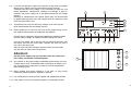
100% recy-cling paper.
Bleached without chlorine.
GB
Imprint
These operating instructions are published by Conrad Electronic GmbH, KlausConrad-Str. 1, 92240 Hirschau/Germany
No reproduction (including translation) is permitted in whole or part e.g. Photocopy, microfilming or storage in electronic data processing equipment, without
the express written consent of the publisher.
The operating instructions reflect the current technical specifications at time of
print. We reserve the right to change the technical or physical specifications.
C Copyright 1997 by Conrad Electronic GmbH. Printed in
Germany.
OPERATING INSTRUCTIONS
If this current is exceeded the power supply is overloaded.
Power Supply
It is not allowed to operate the power supply in damp environments
or outdoors (according to the safety regulations).
PS 302A
Contents
Item No. : 51 1412
1.
2.
3.
4.
5.
Introduction ………………………………………………………….. 2
Safety Rules (Mains connection and exchange of fuses) ………..3
Operational Elements
…………………………………………. 6
Operation ……………………………………………………………. 6
Technical Data ………………………………………………………..8
1. Introduction
This power supply is infinitely variable for voltage and current and can be
universally used for school, work and hobby etc.
2
Power Supply PS 302A.
.
.
.
.
.
.
.
.
.
.
.
.
.
Attention! Read before operation!
Read the manual carefully and completely.
In the case of damage caused by non-observance of the instruction,
the claims under guarantee lapse. We cannot take any liability for
consequential damage. Please read and understand the instructions
before attempting to use the power supply.
Warning! Operation as directed means:
This product is only constructed for connection to an operating voltage
between 0 and 30 VDC at the output terminals.
The power consumption of the connected device must not exceed 2A.
.
.
.
.
.
.
.
.
.
.
.
.
.
.
.
.
.
.
.
.
.
.
.
..
.
.
.
.
11
An electronic current limiter protects the power supply against overload or
a short circuit at the output; a thermo fuse interrupts the load circuit
(output) when the max. temperature is exceeded (>+120°C), in this case
the LED for “TEMP” is on.
After cooling off again the LED goes off, the output is restored in circuit
again.
If there is an overload (short circuit or overload) the output is turned off,
that means the current at the output is more than the preset current limit.
The output voltage remaining at the terminals is only a few mV. When the
short circuit is removed the output is “restored”. The red LED displays the
limiting condition (U or I).
The preset values can be read in a common analog meter using Volt /
Ampere toggle switch. Voltage and current is set over 3 setting knobs. So
an exact setting of the output voltage and output current (current limiting)
is possible.
2. Safety Rules
2.1 The power supply is constructed in protection class I according to VDE
0411 or VDE 0550. it is equipped with a VDE approved mains cable
with a protective conductor and may only be connected to 230 V AC
electric mains with protective grounding.
2.2 Please pay attention that the protective conductor (yellow/green) is
connected in the unit and in the mains, as there is danger to life if the
protective conductor is disconnected. Furthermore pay attention that
the insulation is neither damaged not destroyed.
2.3 Keep power supplies away from children!
2.4 Pay attention to the rules for prevention of accidents in industrial
enterprises prescribed by the Industrial Trade Associations for
electrical installations and production facilities.
10
2.5 When using the power supply in schools and hobby-workshops the
usage has to be controlled by the responsible teachers or skilled
personell.
3
2.6
If covers are opened or parts are removed, except what is possible
without tools, voltage-carrying components can be exposed.
Terminals can also carry voltage. If it is necessary to open the unit
before adjustment, maintenance, repairing or exchange of parts or
modules, the power supply has to be disconnected from all voltage
sources.
Repairing or maintenance of the power supply may only be executed
by skilled personell who know the dangers and the respective rules
(VDE-0100 and VDE-0701).
2.7
Condensers in the unit can still carry voltage, even if the unit has
been disconnected from all voltage sources.
2.8
Please make sure to use only new fuse of the proper rating. Do not
use repaired fuses and do not bridge the fuse holders.
8
7
4a
4c
4b
1
Pull the plug to change the fuses and separate the soldering station
from the mains voltage, as otherwise it will be dangerous to life.
5a
Turn the fuse holder cap to the left with a screwdriver and lift it with
the defect fuse from the fuse holder. Replace the fuse only with a
new one of the same type.
After the fuse has been changed, carefully screw the fuse holder
cap with the new fuse into the fuse holder.
Put the power supply only into operation after the cabinet has
been safely closed and screwed together.
Don’t switch on the power supply immediately after bringing it in from
a cold to warm room. Condensed water might impair or destroy your
unit. Give the power supply time to warm up to room temperature
ithout switching it on.
2.10 When working with power supplies it is not safe
conductive jewelry necklaces, bracelets, rings etc.
6
2
2
2
3
Attention!
2.9
5
9
11
10
to carry metal,
2.11 It is not allowed to connect power supplies with people and animals.
2.12 If the output of one or more power supplies is connected in series
4
9
voltages (>35 VDC), hazardous to life are created.
5. Technical Data
Mains input ………………….. :
230VAC + 6%, - 10%
Frequency…………………….. :
50 Hz
Power consumption…………:
Max. 100VA
Output Voltage………………. :
0 – 30 V DC, stepless
Output current……………….. :
0,01 – 2 A max. stepless
Line Regulation Constant
Voltage at Mains Change
+6% to –10% …………………:
0.05 %
Load Regulation for
100% Load Change
:
< 10 mV
Ripple at Rated Load
:
5 mVeff
Fuse
:
Slow Blow 1A / 250V
(usually T 1A/250V)
Voltage & Current Display
:
Analog Panel meter common for
voltage and current. Selectable by
toggle switch.
Weight
:
approx. 4.3 Kg
Dimensions (W x H x D)
:
225 x 135 x 260 mm
Surrounding Temperature:
Operating Temperature
(min. to max.)
:
+5°C - +40°C
Rel. Humidity
:
Max 85%, not condensing
Barometric pressure
:
600 to 100 hPa
8
2.13 When operating the power supply pay attention to sufficient
ventilation. Never cover the ventilating slots. Place the unit on a
hard, flame resistant base. Make sure good ventilation of the unit is
possible. Cooling of the units is mainly achieved by convection (heat
flow).
2.14 Do not operate charging units and connected loads without
supervision. Take measures to protect and secure the connected
products against operational effects of the power supply e.g. overvoltage (failure of the power supply) and against effects and dangers
orginating from themselves ( undue high power input).
2.15 In the case of error function power supplies can release voltages
more than 50 V DC, this is dangerous even if the output voltage of
the units is below this value.
2.16 For work under voltage only approved tools may be used.
2.17 To avoid an electrical shock, don’t touch directly the output of the
power supplies (output sockets/clamps)
The leads used must be sufficiently insulated and have sufficient
voltage stability and the contacts have to be shockproof (safety
sockets)
2.18 Do not lay metallic bare cables and contacts. All these spots have to
be covered with suitable, flameresistant insulation material or other
measures to protect them against direct contact. Protect all electric
conductors of the connected consumers against direct contact.
2.19 If there are doubts whether a safe usage is still possible the power
supply unit has to be put out of operation and be secured against
unintentional use.
It must be assumed that a safe usage is still possible if
the power supply shows visible damage
• the unit does not work and
• after longterm storage under unfavourable conditions
• after transport strain
•
5
3. Operational Elements
Attention!
See Page No. 9 for figure
During long time operation with a nominal load (30 V / 2 A) or if there
are short circuits. The heatsinks are getting hot. Attention! Danger of
burning !
1. Front Panel
2. Connection clamps (red = +, blue = -) and grounding (yellow/green)
3. Power switch ON/OFF on the rear panel of the unit
4. Controll-LED’s for voltage- 4a current-limitation 4b
and over-heating 4c
5. Control knob to adjust fine voltage
5a. Control knob for coarse voltage adjustment
6. Control knob to adjust current limitation
7. Analog display for DC voltage and current
8. Volt/Amper meter selection toggle switch.
Always pay attention to sufficient ventilation of the power supply and
never cover the ventilating slots on the top and the bottom of the cabinet to avoid damage.
As soon as the LED indicates thermal overload, separate the
connected user/s from the power supply. As soon as the LED is off, the
power supply can be used again (after cooling off).
If you connect a consumer always pay attention that it is not switched
on. If you connect a user which is switched on to the output clamps of
the power supply, sparks might be produced which might damage the
connection sockets and/or the connected leads and/or the clamps.
b) Adjustment of voltage (unloaded output)
11. Heatsink
First turn the panel control knob for the current limitation (6) to the right
(clockwise) until the LED for the current limitation (4b) is off. At the same
moment the LED for voltage adjustment goes on (4a). Now you can select
the desired output voltage. The output of the power supply is potential free,
that means not connected with the earthing conductor. A potential
connection between the power supply and the consumer (load) is possible
via a separate earthing socket between the output sockets (,,+’’ and ,,-‘’).
4. Operation
c) Adjustment of the current limitation
9. Fuse holder on the rear panel of the unit
10. Mains connection for a appliance plug (not contained in delivery)
a) Connection
Connect the earthing contact plug of the power supply with a earthing
contact outlet. First make shure nothing is connected to the output terminals, then switch on the power supply with the power switch.
6
Switch the power supply off and short the output terminals. Switch on the
power supply. The display for the output current shows, depending on the
setting of the control knob for current limitation, any value. Set the current
limit, this means the ,,max. current” when the power supply should be
limiting. After the current limit has been set ,,open the short circuit”, but the
power supply must be switched off before, otherwise a breaking spark
could be produced.
7