1
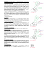
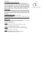
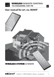
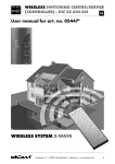
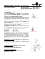
WINTERHOFF GMBH - Egenstraße 2 - 58339 Breckerfeld
Safety coupling with stabiliser:
WS 3000 D-S, 3.000kg
- EG-Nr. 00-0065 e1
WS 3000 H-S, 2.000kg/1.350kg - EG-Nr. 00-0337 e1
WS 3000 L-S, 1.350kg
- EG-Nr. 00-0337 e1
Assembly and operating instructions
1. Technical features
1.1 The ball coupling WS 3000 D-S is suitable for use on central axle drawbar
trailers with an approved total weight of 3.000 kg, an actual minimum trailer
weight of 200 kg and upwards and an approved static support load at the
coupling point of 150 kg. In contrast, the WS 3000 H-S/L-S has the following
specifications: approved total weight 2.000 kg or 1.350 kg.
1.2 The ball coupling is fitted with spring-loaded friction pads which enclose the
coupling ball of the towing vehicle from the front and the back. Pitching and
snaking movements of the trailer are thus reduced or prevented completely.
Optimal damping is achieved with new friction pads after a certain run-in period.
1.3 The ball coupling WS 3000 can only be used together with coupling balls
corresponding to DIN 74058 / ISO 1103 when the neck is free of fittings over a
distance of 35 mm. ( Fig.1)
( instead of 32 mm as per DIN 74058 / ISO 1103 )
The use of the WS 3000 in conjunction with ball pins with screw fastening but with
no additional positive connection facility is prohibited. ( Fig. 2)
With the stabiliser turned on (Fig. 5), the operating lever must be free from vehicle
or installation fittings when driving.
2. Assembly
2.1 The WS 3000 D-S ball coupling is supplied for a drawbar diameter of 50 mm.
Shims are supplied loose to cater for the following different diameters:
Diameter 46 mm
shim = 2,0 mm
Diameter 45 mm
shim = 2,5 mm
Diameter 40 mm
shim = 5,0 mm
Diameter 35 mm
shim = 5,0 + 2,5 mm
The WS 3000 H-S/L-S is supplied for a drawbar diameter of 45 mm with a shim
of 0.5 mm.
The pre-fitted shim is to be removed in the case of a drawbar diameter of 46 mm.
2.2 The WS 3000 D-S ball coupling is fitted using longitudinal (1)+(2) or cross
(1)+(3) screw connections and the hole spacings of 40/50/54 mm. The coupling
WS 3000 H-S/L-S can be fitted using the cross screw connection (1)+(3) and the
hole spacing of 40mm. The fittings are part of the scope of supply and should be
applied as follows: ( Fig. 3)
WS 3000 D-S
Hexagon head screw M12 x 90 with washers on both sides and self-locking nut
for oblong hole (1)
Hexagon head screw M12 x 80 with self-locking nut for the second hole in the
case of longitudinal connection (2) or:
Hexagon head screw M12 x 80 with self-locking nut in the case of cross
connection (3)
WS 3000 H-S/L-S
Hexagon head screw M12 x 80 with self-locking nut for holes (1)+(3)
Fit fixing screw (3) together with stop/profiled washer (4).
Stop and profiled washer are not part of the scope of supply.
Self-locking nuts may only be used once.
Tightening torque for hexagon head screws M12 / M14, 10.9 :
WS 3000 D-S
– 90 Nm
WS 3000 H-S/L-S – 70 Nm
ATTENTION! If the drawbar tube has 14 mm Ø fastening holes, the WS 3000 is
not to be fitted using M 12 screws. It can be fitted using M 14 screws with the
holes enlarged at the factory.
2.3 If the WS 3000 ball coupling is used as a replacement for another type of
coupling, care must be taken in connection with the overrun equipment to ensure
that the shock absorber is refitted properly and that any spacer tubes in the
drawbar are reinstalled correctly. Pease use the Ø 12 x 34 mm or Ø 12 x 49 mm
bolts supplied for this purpose depending upon the drawbar diameter. Use bolts
as a drift when dismantling the fixing screw (2) or (3) (Fig. 3) depending upon the
method used to mount the shock absorber and leave them in the drawbar during
assembly/dismantling of the ball coupling for centering the shock absorber.
Remove the bolts again when pushing the new fixing screw through.
2.4 Proceed as follows to fit the bellow supplied for the WS 3000 D-S.
In the case of drawbar diameters of 40 - 50 mm, simply push the bellow, prior to
mounting the WS 3000 D-S, over the drawbar tube. In the case of diameters of
60 - 70 mm, the small connecting piece in front of the rubber lip must be cut off
using a knife, for example. When the cross screw connection is applied, also cut
out the bottom marked hole; cut out both laterally marked holes for longitudinal
screw connection.
3. Operating instructions
3.1 Coupling
The opened ball coupling is placed on the coupling ball of the towing vehicle
( Fig.4 ).
The support load and possible additional loading of the drawbar serves to cause
the ball coupling to close automatically and the side securing lugs (1) are parallel
in relation to the securing surfaces on the housing ( Fig. 4 ).
3.2 Activating the stabiliser
Here, the operating lever must be pushed down out of its closed position to the
stop. ( Fig. 5 ). In doing so, the spring assembly which generates the pressing
force via the friction pads onto the ball coupling is tensioned. Upon completion of
this operation, the operating lever is roughly parallel to the axis of the drawbar. It
is possible to drive with the stabiliser deactivated, for example, when
manoeuvring.
3.3 Switching the stabiliser off
Pull the operating lever slowly upwards in order to turn off the stabiliser ( Fig.6 ).
3.4 Disconnection
Disconnect the lighting plug and contact-breaking cable, turn off stabiliser (Fig.6),
simultaneously pull back and lift the operating lever ( Fig. 6 ) such that the side
securing lugs (1) swing over the securing surfaces and the operating lever can be
moved to the open position. The trailer can now be uncoupled from the towing
vehicle with the aid of a jockey wheel.
Note: when uncoupling, the overrun device must be released i.e. the bellow is
stretched.
If not used for any lengthy period of time, the trailer should be parked with the ball
coupling closed. For this purpose, lift up the open operating lever ( Fig. 4 ) and at
the same time pull the ball socket ( movable element with friction pad – Fig. 8 )
forward or press the safety ball into the ball space and slowly close the operating
lever.
3.5 Checking the stabiliser
When the trailer has been hooked up and the stabiliser activated, the condition of
the friction linings can be checked. The wear indicator located on the top of the
operating lever ( Fig. 7 ) displays a bar graph marked with + and - symbols. The
ball coupling is set at the factory such that the pin visible in the oblong hole is
positioned under the + symbol on the bar graph when new friction pads have
been fitted.
3.6 Anti-theft device
The WS 3000 D-S/H-S/L-S ball couplings can be locked both in coupled and
disconnected condition with the ROBSTOP WS 3000 by using the hole on the
side of the housing.
4. Maintenance
4.1 Coupling ball 50 mm Ø on towing vehicle
It should be dimensionnaly correct, undamaged, clean and free of grease.
On coupling balls with dacromet coating ( mat silver anti-corrosion coating ) as
well as on painted couplings, the coating must be completely removed using
emery cloth, grain size 200 – 240, prior to the first journey so that it does not
accumulate on the surfaces of the friction pads. The surface of the coupling ball
must be „ bright metal “. A damaged or dirty coupling ball causes increased
wear of the friction pads; a greasy coupling reduces the stabilising effect
significantly. Thinners or spirits, for example, are suitable for cleaning the ball.
4.2 Ball coupling
The interior of the ball coupling in the area of the friction pads is to be kept clean (
Fig. 8 ). If the friction pads are dirty, the surface can be cleaned using emery
cloth, grain size 200 – 240. Subsequently clean the surface with benzine or spirit.
All movable bearings and bolts must be slightly oiled. Regular maintenance and
care will serve to improve the service life, function and safe use of your WS 3000
ball coupling.
4.3 Replacing the friction pads
The friction pads can be replaced in the event of wear.
We supply a replacement set of 2 pads for the purpose of replacing the front and
rear pads. Part No.: 2 x 6209
Please observe the detailed assembly instructions contained in the replacement
set
4.4 Driving noises
Noises caused by friction between the pads and the ball can occur when driving
but which have no effect on the function of the coupling itself.
Noise can also be caused by:
- Dirt between friction pad and ball
Remedy:
Service the ball coupling / drawbar coupling as decribed in chapters
4.1/4.2
or replace the friction pads, refer to chapter 4.3
- Dry running of drawbar/draw tube in the bushings of the overrun device
Remedy:
Grease the bushings using the grease nipples. Remove bellow and grease
the drawbar
- Detachable ball coupling on towing vehicle
Remedy:
Regrease detachable ball coupling on the locking mechanism
( refer to operating instructions for trailer device ).