1
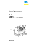
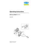
Operating Instructions Control unit WSE2226 USA Index 000 Original operating instructions 10993031 en USA / 13.08.2015 Congratulations! With a Hydrostress unit from TYROLIT, you have chosen a tried and tested piece of equipment which has been designed and built to leading technical standards. Only genuine TYROLIT Hydrostress replacement parts can guarantee quality and interchangeability. If maintenance work is neglected or carried out inexpertly we will be unable to honour our warranty obligations. Any repair work must be carried out by trained personnel only. Our after sales service is available to help ensure that your TYROLIT Hydrostress units remain in perfect working order. We hope that working with your TYROLIT unit will be a satisfying and fault-free experience. TYROLIT Hydrostress Copyright © TYROLIT Hydrostress TYROLIT Hydrostress AG Witzbergstrasse 18 CH-8330 Pfäffikon Switzerland Tel. 0041 (1) 952 18 18 Fax 0041 (1) 952 18 00 Page 2 TYROLIT Hydrostress AG 1 Safety DANGER Failure to comply with the safety instructions in the «Safety Manuals / System Manuals» may result in serious injuries or even death. XX Make sure that the «Safety Manuals / System Descriptions» for the relevant type of saw have been fully read and understood. DANGER Death or serious injury can be caused by sudden start-up of the machine. XX Before switching on the system, ensure that no other persons are present in the danger areas. XX Switch the system off before connecting or disconnecting cables. XX On leaving the system switch off and make safe so that it cannot be switched on again. Death or serious injury as a result of the sawing machine continuing to run after an accident. XX Ensure that the EMERGENCY STOP button can be reached quickly. Electric shock from live cables and connectors. XX Switch off the control unit WSE2226 before connecting or disconnecting cables. XX Ensure that the power supply is earthed and fitted with a residual current operated protective device (FI Type B) with a maximum residual current of 30mA. Risk of fire due to incorrect mains voltage. XX Make sure that the mains voltage and mains frequency correspond with the mains settings of control unit WSE2226. 1.1 Action in an emergency XX Press the EMERGENCY STOP button on the remote controller. If the EMERGENCY STOP has been activated on the radio remote controller, the LED pilot lamp flashes quickly. In an emergency the sawing machine can be also switched off using the main switch of control unit WSE2226. Emergency Stop Page 3 TYROLIT Hydrostress AG 2 Description 2.1 Main components Control unit Main components Control unit 1 2 3 4 5 6 7 2.2 Operating hours counter Main switch Feed motor connection Remote controller connection Mains connector Water nipple / water inlet Water connection / water outlet 8 9 10 11 12 13 Main motor connection Name plate Indicator lights Mains system selection button Reset button Radio remote controller Main components of radio remote controller Main components of remote controller 1 2 3 4 5 6 7 Page 4 Feed potentiometer On / Off Main motor Main motor potentiometer Water On / Off Diameter selector switch Traverse feed joystick Starter switch 8 9 10 11 12 13 Pulse switch Control unit EMERGENCY STOP Indicator lights Warning light (radio & battery) Position lock switch (Traverse feed) Casing TYROLIT Hydrostress AG 2.3 Remote controller The remote controller can be replaced by an accumulator or a battery operated radio remote controller. The remote controller can also be operated using a cable. Radio remote controller The transmitter and receiver are a pair of matched units. They cannot be used with other devices. Transmitter = radio remote controller Receiver = control unit Remote controller 2.4 Operating modes Rechargeable battery operation: The interchangeable rechargeable battery is inserted in the base of the casing. The operating period with a fully charged battery is approximately 12 hours. A shorter operating period can be expected at low temperatures. The reception distance is 27 yards. Battery operation: The battery holder is included in the scope of supply and allows operation with three 1.5 V AA batteries. The reception distance is 27 yards. Cable operation: The cable insert is included in the scope of supply and allows connection of the remote controller to the control unit WSE2226. The cable length is 11 yards. Cable operation makes it possible to work in areas where radio operation is not allowed (e.g. hospitals). With cable operation all control signals are transmitted via the power cable. The rechargeable/ordinary battery holders may not be inserted in the base of the casing during cable operation. Page 5 TYROLIT Hydrostress AG 2.5 Accessories for remote controller The battery charger is exclusively for recharging the interchangeable rechargeable battery. The battery holder must not be inserted. Accessories 1 2x Interchangeable rechargeable batteries 2 Rechargeable battery charger Rechargeable battery charger with 10-30 VDC connection 3 Remote control cable 4 Battery holder 5 Key 6 Adapter No. 10984306 No. 10984305 No. 10984840 No. 10991362 No. 10984307 No. 10984309 No. 10993019 During cable operation no interchangeable rechargeable battery or battery holder must be inserted into the remote controller. Page 6 TYROLIT Hydrostress AG 3 Connections 3.1 Connecting remote controller and motor connections 99 The control unit is isolated from the power supply 99 Connectors/plugs are clean 99 Cables are undamaged XX 3.2 Connecting the mains and water supply 99 The power supply is earthed and fitted with a residual current operated protective device (FI Type B max. residual current 30mA) 99 Cable cross-section is sufficient: for up to 27 yards long 5 x AWG 9, more than 27 yards long 5 x AWG7 Page 7 TYROLIT Hydrostress AG 4 Operation 4.1 Overview of operating elements Controls 1 2 3 4 5 6 7 Page 8 Position lock switch (Traverse feed) Water On / Off EMERGENCY STOP Pulse switch control unit Starter switch Feed potentiometer On / Off, main motor 8 9 10 11 12 13 Main motor potentiometer Diameter selector switch Feed joystick Main switch Control unit Reset button Mains system selection button TYROLIT Hydrostress AG 4.2 Starting the control unit WSE2226 CAUTION The control unit WSE2226 can be damaged if it slips or overturns! XX Make sure that the control unit WSE2226 stands horizontally (handle at top). 99 Control unit WSE2226 is connected to the mains and the water supply. 99 The sawing machine is connected to the control unit WSE2226. 99 The remote controller EMERGENCY STOP has been deactivated. 99 The control unit WSE2226 is not exposed to direct sunlight. Starting the control unit WSE2226 XX Move the controls shown below on the remote controller to the 0 position. Feed potentiometer (6) Starter switch (5) Feed joy stick (10) Main motor On/Off (7) XX Switch on the control unit WSE2226 using the main switch (11). XX Switch on the radio remote controller using the starter switch (5). –– Warning lights (radio and battery) at first show red –– An audible signal sounds simultaneously –– Indicators flash coloured –– Second audible signal sounds –– Indicators show coloured –– Warning light flashes green XX Press the pulse switch (4) on the radio remote controller briefly to the ON-position. All indicator lights except the warning light and the group alarm on the radio remote controller go off. XX Press the reset button (12) on the control unit. XX Press the remote control pulse switch (4) briefly in the ON-position. The the control unit 'ready' lights show green. XX Open the water valve on the system supply line. XX Press the Water On/Off switch (2) on the remote control unit to I. –– Water flows from the cutting tool XX Press the main motor On/Off switch (7) on the remote controller to position I. –– The electric motor starts when the main motor potentiometer is in the max. position. XX The control unit WSE2226 has started up and is ready for operation. Page 9 TYROLIT Hydrostress AG 4.2.1 Remote control frequency change Remote control frequency change The remote control systems are equipped with a frequency generator for frequency selection. If the systems malfunction or the radio link is interrupted (another transmitter, range, empty battery), the systems immediately go into EMERGENCY OFF mode. New frequency search: You can select the next frequency by switching the start switch on the remote control off and back on. The off/on switching procedure is limited to four attempts (channels). If the system has not found a suitable frequency after four attempts, you must change to cable operation. Page 10 TYROLIT Hydrostress AG 4.3 Selecting mains network The control unit WSE2226 is preset for a 63A power supply network (63A button lights up). It is possible to switch over to a 32A power supply network. The system automatically returns to the 63A settings when it is restarted. XX To set the power supply network to 32A press the power network selector (13), the button light goes out. Resetting must take place directly after switching on the control unit WSE2226. 4.4 Tool soft start The control unit WSE2226 provides a facility for a tool soft start. Proceed as follows: XX Starting the control unit WSE2226, see 4.2. XX Turn the main motor (8) potentiometer to the 0 position. XX Press the switch main motor (7) to I. XX Select the desired output level, see 4.5. XX Turn the main motor (8) potentiometer slowly to 100% power. 4.5 Selecting tool station After the control unit WSE2226 has been started correctly the tool station can be selected. Selecting the power level Proceed as follows: XX Set the diameter selector switch to the desired tool and turn the main motor potentiometer from 0 to 100%. XX Check gear at gearbox of drive motor. The tool stations may not be changed during operation. The tool stations are set with reference to the tool diameter for the optimum rotational speed and cutting performance. The rotational speed can be reduced using the main motor potentiometer but at the same time the power is reduced. Page 11 TYROLIT Hydrostress AG 4.6 Power control The main motor and the feed motor power are controlled via the potentiometers. Power control Feed motor potentiometer (6) Main motor potentiometer (8) 4.7 Adjusting the feed The feed movements are selected with the joystick. Adjusting the feed During the cutting process the feed speed is automatically assisted by a feed facility. Page 12 TYROLIT Hydrostress AG 4.7.1 Manually adjusting the feed speed 99 Control unit WSE2226 has started XX Select the required feed speed via the feed potentiometer (6). 4.7.2 Feed stop So that the joystick does not have to be held in position during the travel feed motion the travel feed can be locked. Proceed as follows: XX Push the joystick in the desired travel direction and at the same time press the locking switch (1). XX When the joystick and the locking switch are released the feed is locked. In order to release the feed lock, move the joystick slightly in any desired direction. 4.8 Switching off the control unit WSE2226 Proceed as follows: XX Switch off electric motor (7) On / Off main motor. XX Turn off cooling water, switch (2) Water On / Off. XX Close water valve on control unit WSE2226. XX Turn the start switch (5) on the remote controller to the 0 position. XX Switch off the control unit WSE2226 using the main switch (11). Only stop the wall saw WSE2226 using the EMERGENCY STOP function in an emergency. CAUTION Frost damage to control unit WSE2226! Heat damage to control unit WSE2226! XX Blow out any water if there is a risk of frost (see chapter 4.9, Blowing out water). XX Direct sunlight on the WSE2226 control unit must be avoided. 4.9 Blowing out the water 99 Main switch is set to OFF XX Disconnect the mains plug. XX Disconnect all water lines. XX Connect blow out pump to the water nipple. XX Blow out water until all of the cooling water has been removed. XX Remove the pump. Page 13 TYROLIT Hydrostress AG 4.10 Deactivating EMERGENCY STOP If the EMERGENCY STOP is activated on the radio remote controller, the radio and battery light (8) flashes. Deactivating EMERGENCY STOP The following controls must be moved the 0 position: Feed potentiometer (6). Feed joy stick (10). Main motor On/Off (7). Turn the EMERGENCY STOP button (3) clockwise. Press pulse switch control unit (4) to the ON position. 4.11 After termination of work Proceed as follows: XX Turn the main switch on the control unit WSE2226 to the 0-position. XX Withdraw the mains plug (Control unit WSE2226). XX Disconnect the water hoses from control unit WSE2226. XX Blow out the water from all the lines (blow out pump). XX Disconnect electric cable. XX Clean the control unit WSE2226, the remote controller and the cable with a damp cloth. Cleaning using high pressure cleaning equipment is not permitted. Products containing cleaning agent can damage parts of the control unit WSE2226, the radio remote controller and the cable. Page 14 TYROLIT Hydrostress AG 5 Reacting to displays Symbols on the control unit / remote controller Symbols on the control unit Symbols on the remote controller 1 2 3 4 5 6 7 8 9 10 11 Service Control unit external fault Fault within the control unit Temperature Mains connector EMERGENCY STOP Potentiometers Radio and battery remote control Cooling water Group alarm Ready for operation lights Page 15 TYROLIT Hydrostress AG Power and error displays on the control unit Symbol Response Possible cause Action Lights up red After the first 100 operating hours, then after every 200 operating hours. Carried out only by TYROLIT Hydrostress AG or an authorised representative Lights up red Fault: - current overload - short circuit - earth fault Main motor - defective feed motor The control unit will not start. XX Check network connection. XX Check cable. XX Replace feed motors. XX Contact TYROLIT Hydrostress AG customer service. Lights up red Defective - main contactor - brake resistance - over current Motor - CAN fault - group fault The control unit will not start. XX Contact TYROLIT Hydrostress AG customer service. XX Check network connection. Lights up red Over heated - cooling element - control unit - main motor The control unit will not start. XX Check cooling. Wait until it can be restarted. Before starting press the reset button. XX Avoid direct contact with sun light. Lights up red Phase missing The drive unit will not start or switches off during operation. XX Check the mains fuse in the distribution box and switch it on if necessary. XX Have the site power supply checked. XX Have the extension cables, plugs and sockets checked for faults. Page 16 Lights up red The EMERGENCY STOP has been activated - CAN fault XX Deactivate the EMERGENCY STOP. XX Contact TYROLIT Hydrostress AG customer service. Lights up red Feed potentiometer not in zero position The control unit will not start. XX Set the feed potentiometer to 0. TYROLIT Hydrostress AG Power and error displays on the remote controller Symbol Response Possible cause Action Flashes red Rechargeable battery voltage too low XX Recharge rechargeable battery. Flashes rapidly green No radio connection The EMERGENCY STOP has been activated XX Switch on the control unit. XX Defective receiver. XX No receiver matched connection, see page 5. No light shows No water flow The control unit will not start, motor does not run. XX Press the cooling water button. (LED shows blue). Lights up red or flashes • Group alarm on the control unit • When the pulse switch control unit is operated, the main motor On/Off switch is in the position On XX Observe control unit fault indicators. XX Press the control unit reset button. Lights up green The motor is ready to start No light shows Contactor not ready XX Operate control unit pulse switch. Shows the current power range Ideally: At the third, orange coloured diode (In iron fourth, red diode). Page 17 TYROLIT Hydrostress AG 6 Servicing and maintenance After damage X X X X XX Check the condition and cleanliness of connections. X X X X XX Check water lines for cleanliness and leaks. X X X X X X X X Annually XX Check the condition and cleanliness of electric cables, plugs/connectors and switches. Weekly After faults Water economy On finishing work Electrical system Before starting up Maintenance and servicing table X XX Clean water filters. XX Blow out the water if there is a risk of frost. X Entire WSE2226 control unit XX Clean with damp cloth no high pressure cleaner X Service XX To be performed by TYROLIT Hydrostress AG or an authorised workshop. First service after 100 operating hours Further services after every further 200 operating hours Cleaning using high pressure cleaning equipment is not permitted. Cleaning using high pressure cleaning equipment can damage the control unit and the remote controller. Products containing cleaning agent can damage parts of the control unit WSE2226, the radio remote controller and the cable. 6.1 Clean water filter Clean water filter Page 18 TYROLIT Hydrostress AG 7 Faults Faults Faults Possible cause Solution Control unit does not run although the mains cable is connected Control unit is switched off XX Switch control unit on, see Chapter 4. Mains cable is defective XX Replace the mains cable. No voltage at the power supply (building site) XX Check the power supply. Power supply phases incorrectly connected XX Check the power supply. Phase missing See the chapter 5 entitled «Reacting to displays». The control unit starts and then cuts out again Building site power supply cut-off unit trips XX Check and if necessary adapt the cut-off protection. XX If necessary change the power supply. XX See chapter entitled «Reacting to displays». No power, even though the control unit is running Incorrect voltage Defective main motor XX Make sure that the control unit voltage and frequency match the mains supply specifications. XX Contact TYROLIT Hydrostress AG customer service. The control unit suddenly cuts out Over or under voltage XX Check the power supply. Refer to fault indicator. Cross section of power supply cable too small XX Check the power supply. Defective plug connection XX Check the plug connection. XX Check the power supply. Group alarm XX Refer to fault indicator • Main motor potentiometer is in 0-position • Defective main motor On / Off switch on remote controller The remote controller 'ready to operate' light does not come on. XX Contact TYROLIT Hydrostress AG customer service. XX Do not start control unit, see Chapter 4.2 EMERGENCY STOP activated XX Deactivate EMERGENCY STOP, see Chapter 4.10. Overheating XX Check the water circuit and the plug-in couplings. XX Refer to fault indicator. No water XX Switch on the water supply. XX Refer to fault indicator. Remote controller not working Rechargeable battery or battery have too little charge XX Replace rechargeable battery and recharge or install cable operation. XX Replace batteries. Feed potentiometer indicates no function • Defective potentiometer in the remote controller • Feed motors not connected • Defective feed motor • Joystick is in the zero position XX Contact TYROLIT Hydrostress AG customer service. XX See Chapter 3.1 / 4.6 / 4.7 Feed motor fails to build up power Remote controller potentiometer is defective or in the 0-position XX Contact TYROLIT Hydrostress AG customer service. XX See Chapter 4.7.1 Defective cable XX Contact TYROLIT Hydrostress AG customer service. Motor fault XX Contact TYROLIT Hydrostress AG customer service. Main motor is not running Page 19 TYROLIT Hydrostress AG Faults Faults Possible cause Solution No water emerging Water line blocked XX Clean the water line. Water valve on the supply or water hose are closed XX Open the water valve. Insufficient water pressure XX Make sure that the water pressure is at least 2 bar. Water filter is blocked XX Remove filter and clean XX Contact TYROLIT Hydrostress AG customer service. Switch for the radio remote controller defective XX Contact TYROLIT Hydrostress AG customer service. • Water valve on the control unit is defective • Switch for the radio remote controller defective XX Stop water leaks using the hose water valve. XX Contact TYROLIT Hydrostress AG customer service. Uncontrolled water leak Group alarm on the remote controller Page 20 XX See chapter entitled «Reacting to displays». TYROLIT Hydrostress AG 8 Technical data Dimensions in inch Technical data Parameter Value Type Frequency converter Weight Control unit WSE2226 incl. remote controller 57.3 Ibs Remote controller separate 4.4 Ibs Protection class IP 65 (4.4X NEMA rating) Connection values 380 to 420 VAC / 50 Hz / 60 Hz Max. current consumption 38 A Power With 32 A power supply network 17 kW With 63 A power supply network 26 kW Controller / remote controller 24 VDC / 3.6 VDC Feed drives 48 VDC Main drive unit 400 VAC, 0...400 Hz Cooling the control unit Water cooling the power semiconductors Cooling water flow rate min. 1.05 gmp at max 77 °F Water connection min. 29psi / max. 87psi Control unit WSE2226 incl. remote controller +14°F to +104°F Internal control voltages Water Usage temperature Page 21 TYROLIT Hydrostress AG 9 Spare parts Page 22 TYROLIT Hydrostress AG Page 23