1
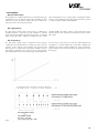
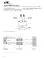
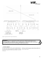
OPERATING INSTRUCTIONS for Flow Meters of the series: ”Ex-Type VHM“ VSE Volumentechnik GmbH Hönnestraße 49 58809 Neuenrade / Germany Phone + 49 (0)23 94 /616 30 Fax + 49 (0)23 94 /616 33 E-Mail [email protected] Internet www.vse-flow.com 1 Table of Contets Page Important basic information. . . . . . . . . . . . . . . . . . . . . . . . . . . . . . . . . . . . . . . . . . . . . . . . . . . . . . 3 Functional description of the flow meter in areas subject to explosion hazards. . . . . . . . . . . . . 4 Flow Meter Selection. . . . . . . . . . . . . . . . . . . . . . . . . . . . . . . . . . . . . . . . . . . . . . . . . . . . . . . . . . . 4 Declaration of Conformity. . . . . . . . . . . . . . . . . . . . . . . . . . . . . . . . . . . . . . . . . . . . . . . . . . . . . . . 4 General requirements for operation. . . . . . . . . . . . . . . . . . . . . . . . . . . . . . . . . . . . . . . . . . . . . . . 4 Maximum operating pressure. . . . . . . . . . . . . . . . . . . . . . . . . . . . . . . . . . . . . . . . . . . . . . . . . . . . 5 Statement to EU-Directive 97/23/EG, Pressurized Devices . . . . . . . . . . . . . . . . . . . . . . . . . . . . 5 Flow rate measurement range. . . . . . . . . . . . . . . . . . . . . . . . . . . . . . . . . . . . . . . . . . . . . . . . . . . . 6 Installing the flow meter. . . . . . . . . . . . . . . . . . . . . . . . . . . . . . . . . . . . . . . . . . . . . . . . . . . . . . . . . 6 Cleaning and rinsing the pipes before operation. . . . . . . . . . . . . . . . . . . . . . . . . . . . . . . . . . . . . 7 Flow meters in environments subject to an explosion hazard . . . . . . . . . . . . . . . . . . . . . . . . . . . 7 General information on using devices with intrinsically safe circuits. . . . . . . . . . . . . . . . . . . . . . 9 VSE VHM Ex-type flow meters. . . . . . . . . . . . . . . . . . . . . . . . . . . . . . . . . . . . . . . . . . . . . . . . . . . . 9 Isolated switching amplifier MK 13-P-Ex0/24VDC/K15. . . . . . . . . . . . . . . . . . . . . . . . . . . . . . . 9 Technical data for the isolated switching amplifier MK 13-P-Ex0/24VDC/K15 . . . . . . . . . . . 11 Control drawings. . . . . . . . . . . . . . . . . . . . . . . . . . . . . . . . . . . . . . . . . . . . . . . . . . . . . . . . . . . . . 12 Installation of VSE flow meters in hazardous areas . . . . . . . . . . . . . . . . . . . . . . . . . . . . . . . . . . 15 Preamplifier. . . . . . . . . . . . . . . . . . . . . . . . . . . . . . . . . . . . . . . . . . . . . . . . . . . . . . . . . . . . . . . . . . 17 General information. . . . . . . . . . . . . . . . . . . . . . . . . . . . . . . . . . . . . . . . . . . . . . . . . . . . . . . . 17 The single pick-up. . . . . . . . . . . . . . . . . . . . . . . . . . . . . . . . . . . . . . . . . . . . . . . . . . . . . . . . . . 17 The dual pick-up . . . . . . . . . . . . . . . . . . . . . . . . . . . . . . . . . . . . . . . . . . . . . . . . . . . . . . . . . . . 17 Application with directional detection. . . . . . . . . . . . . . . . . . . . . . . . . . . . . . . . . . . . . . . . . . . . 18 Custom solutions. . . . . . . . . . . . . . . . . . . . . . . . . . . . . . . . . . . . . . . . . . . . . . . . . . . . . . . . . . . . . . 19 Safety instructions for installation and operation in hazardous areas. . . . . . . . . . . . . . . . . . . 20 Maintenance and repairs . . . . . . . . . . . . . . . . . . . . . . . . . . . . . . . . . . . . . . . . . . . . . . . . . . . . . . 21 Maintenance and repair of devices . . . . . . . . . . . . . . . . . . . . . . . . . . . . . . . . . . . . . . . . . . . . . . 21 Technical data for the VHM flow meter. . . . . . . . . . . . . . . . . . . . . . . . . . . . . . . . . . . . . . . . . . . 21 Dimensions for VHM flow meter . . . . . . . . . . . . . . . . . . . . . . . . . . . . . . . . . . . . . . . . . . . . . . . . 22 Dimensions of the AHM mounting plate.. . . . . . . . . . . . . . . . . . . . . . . . . . . . . . . . . . . . . . . . . . . 23 Type Code for VHM/AHM. . . . . . . . . . . . . . . . . . . . . . . . . . . . . . . . . . . . . . . . . . . . . . . . . . . . 24 Technical data for VIL*-*S**/Ex, VTL*-S**/Ex single pick-ups. . . . . . . . . . . . . . . . . . . . . . . . 25 Electronic connection data for VIL*-*S**/Ex, VTL*-*S**/Ex. . . . . . . . . . . . . . . . . . . . . . . 25 Housing data for VIL*-*S**/Ex, VTL*-*S**/Ex, Type Plate for VIL*-*S**/Ex, VTL*-*S**/Ex. 25 Technical data for VEL*-*S**/Ex single pick-ups. . . . . . . . . . . . . . . . . . . . . . . . . . . . . . . . . . . . 26 Electronic connection data for VEL*-*S**/Ex. . . . . . . . . . . . . . . . . . . . . . . . . . . . . . . . . . . . 26 Housing data for VEL*-*S**/Ex, Type Plate for VEL*-*S**/Ex . . . . . . . . . . . . . . . . . . . . . . 26 Technical data for VDL*-*S**/Ex dual pick-ups. . . . . . . . . . . . . . . . . . . . . . . . . . . . . . . . . . . . . 27 Electronic connection data for VDL*-*S**/Ex. . . . . . . . . . . . . . . . . . . . . . . . . . . . . . . . . . . . 27 Housing data for VDL*-*S**/Ex, Type Plate for VDL*-*S**/Ex. . . . . . . . . . . . . . . . . . . . . . 27 Type codes - signal pick-ups. . . . . . . . . . . . . . . . . . . . . . . . . . . . . . . . . . . . . . . . . . . . . . 28 Technical data for VHM Titan. . . . . . . . . . . . . . . . . . . . . . . . . . . . . . . . . . . . . . . . . . . . . . . . . . 29 Dimensions for VHM Titan. . . . . . . . . . . . . . . . . . . . . . . . . . . . . . . . . . . . . . . . . . . . . . . . . . . . . 29 Type code for VHM Titan. . . . . . . . . . . . . . . . . . . . . . . . . . . . . . . . . . . . . . . . . . . . . . . . . . . . . . 30 Technical data for single pick-ups VRL*-*S**/Ex; VWL*-S**/Ex for VHM Titan. . . . . . . . . . . 31 Electronic connection data for VRL*-*S**/Ex; VWL*-S**/Ex for VHM Titan. . . . . . . . . . . 31 Housing data for VRL*-*S**/Ex; VWL*-S**/Ex for VHM Titan, Type Plate for VRL*-*S**/Ex; VWL*-S**/Ex for VHM Titan. . . . . . . . . . . . . . . . . . . . . . . . . . 32 Type code - signal pick-up for VHM Titan. . . . . . . . . . . . . . . . . . . . . . . . . . . . . . . . . . . . . . . . . . 32 Wiring diagram with isolated switching amplifier . . . . . . . . . . . . . . . . . . . . . . . . . . . . . . . . . . . 33 Media and ambient temperatures. . . . . . . . . . . . . . . . . . . . . . . . . . . . . . . . . . . . . . . . . . . . . . . . 33 Flow meter labels and certifications . . . . . . . . . . . . . . . . . . . . . . . . . . . . . . . . . . . . . . . . . . . . . . 33 Summary of the safety-related technical data . . . . . . . . . . . . . . . . . . . . . . . . . . . . . . . . . . . . . 34 EC-Type Examination Certificate. . . . . . . . . . . . . . . . . . . . . . . . . . . . . . . . . . . . . . . . . . . . . . . . 35 FM-Certificate of Compliance . . . . . . . . . . . . . . . . . . . . . . . . . . . . . . . . . . . . . . . . . . . . . . . . . . 39 . 2 Important basic information Dear customer, dear user These installation and operating instructions should provide you with the information you need to properly install and commission the flow meter in potentially explosive hazardous areas according to the regulations. The installation, commissioning, and testing are only to be performed by trained and qualified personnel with knowledge of the relevant national regulations relating to explosion protection. These operating instructions must be read and followed carefully to ensure proper, trouble-free, and safe operation of the flow meter. VSE is not liable for any damage incurred resulting from not complying with the instructions in this operating instruction. It is not permitted in any case to open the device. These operating instructions for flow meters in the series „VHM in Ex-Version“ from VSE must be stored so that they can be read at any time by the group of authorized personnel. Chapters may not be taken out of these instructions at any time. A missing operating instructions manual or missing pages in operating instructions must be replaced immediately. VSE can supply you with new operating instructions or you can download the operating instructions from the Internet (www.vse-flow.com). The operating instructions must be given to each subsequent user of this product. Legal Information This document is not managed by an updating service of VSE Volumentechnik GmbH. Changes to this document may be made without notice. VSE Volumentechnik GmbH does not provide any implicit guarantees of commercial qualities and suitability for a specific purpose. If the device has been opened, modified or incorrectly connected to the electrical circuits, the explosion protection warranty is void, and therefore the guarantee of VSE Volumentechnik GmbH for safe operation in potentially explosive areas is void. VSE Volumentechnik GmbH is not liable in any way for personal injuries or damage to goods resulting from improper installation or improper operation of the flow meter. Operating manual – No.: E060054 ( E ) Datum: 20/09/2007 3 • Functional description of the flow meter in areas subject to explosion hazards Flow meters from VSE Volumentechnik GmbH measure the volumetric flow of fluids using the gear method. The two gears in the meter are set in motion by the fluid flowing through the flow meter. The motion of each tooth of the gear is measured by a single or dual signal pick-up that is securely mounted to the flow meter. When the gear rotates, each signal pick-up generates a digital output signal when a tooth of the gear passes through the detection area. Each time a tooth passes, the single signal pick-up outputs one signal, or in case of a dual pick-up, 2 or 4 electrical output pulses, depending on the jumper settings. The gap between the teeth and the housing encloses a volume of fluid, that is transported out, when the gear rotates. This volume of fluid displaced by one gap / tooth mesh, is called the measurement volume V. This measurement volume Vm determines the value of the pulse depending on the size of the flow meter. Vm (l/Imp.) = 1/K-factor The Ex-version of the flow meters in the „VHM“ series are used in fluid technology applications in areas subject to an explosion hazard. The preamplifiers of this „Ex-version“ output a modulated digital signal. This switching pulse is amplified and digitized by an isolated switching amplifier. The signal frequency of the output pulse is processed in the electronics receiving the signal and is proportional to the speed of rotation of the gear and the flow rate. The flow rate corresponds to the volume trans- ferred, which is measured continuously by electronically counting the output pulses. • Flow Meter Selection The right choice (rating) of the type and size of the flow meter is the deciding factor for the trouble-free and safe operation. Due to the wide variety of applications and flow meter versions, the technical data provided in the VSE catalogs are of a general nature. Certain properties of the devices depend on the type, size, and measurement range, as well as on the fluid to be measured. Please contact VSE for exact type and size specifications. • Declaration of Conformity „VHM“ series flow meters for areas subject to an explosion hazard have been tested for their electromagnetic compatibility and noise emission according to the EMC regulations, and meet the requirements of the applicable, legally required EMC directives. They cannot be operated independently. They must be connected to a power source via a cable, and they output digital signals for electronic processing. There is a declaration of conformity available for all flow meters. It can be obtained upon request. Since the EM-compatibility of the overall measurement system also depends on how the cables are routed, on proper connection of the shielding and on every device connected to the system, it must be ensured that all components meet the requirements in the EMC guidelines and that the electromagnetic compatibility of the entire system, machine or plant is guaranteed. All flow meters are tested according to the applicable, legally required EMC directives EN 55011 and EN 61000. „VHM“ Ex-type flow meters are authorized for use in areas subject to a explosion hazard and fulfill the basic health and safety requirements relating to the design and construction of devices and protective systems according to Appendix II of Directive 94/9/EC (ATEX95) and NEC/ NFPA70. Due to their fulfillment of the European standards EN 50014, EN 50020, and EN 50284, US-standards FM3600, FM3610 and FM3810. These devices fulfill the legal health and safety requirements and are certified by accredited certification agencies. You will find an EC-Type Examination Certificate on page 35. The label for EC-conformity is the CE symbol, which is placed on all flow meters. The FM-certificate of compliance is on page 39. • General requirements for operation Before installation or operation, you must check the following properties of your system and take the following aspects of the corresponding conditions in your system into account for trouble-free and safe operation of the system. 1. The medium to be processed Is the flow meter suitable for the medium? Is the medium viscous or abrasive? Is the medium dirty or is there contamination and suspended particles in the medium? What is the size of the particles of the solid material and could they block the meter? Are there any fillers or other additives in the medium? Is it necessary to install a hydraulic filter before the meter? Are the pipelines clean and free of scraps left over from the installation such as shavings or weld splatter? Is the tank clean and can any foreign material escape from of the tank and into the pipeline system? Is the type of medium changed often and is the system thoroughly rinsed after changing? Has all air been completely bled from the pipes and the overall system? Which types of cleaners are used? Can the seals withstand the cleaning agents and medium? Are the seals suitable for use with the medium to be measured (compatible with the seals)? 4 2. Hydraulic properties of the system Is the maximum operating pressure of the system smaller than the maximum permissible operating pressure of the flow meter? Is the maximum pressure drop ∆p (on the flow meter) below the maximum permissible pressure drop? Is the pressure drop ∆p excessively large on the flow meter, when the maximum flow rate (at high viscosities, for example) is reached? Is the present flow rate within the flow rate range of the flow meter (depending on the viscosity)? Note that the flow rate range is reduced at high viscosities! Is the maximum temperature of the medium within the temperature range of the flow meter? Is the pipe cross-section large enough and are there any large pressure drops in the system? Are the hydraulic connections (supply and return) correctly connected and sealed? Does the pump have enough power to operate the system? A blocked flow meter can stop the flow throughout the system. Is there an overpressure valve / bypass present in the system? 3. Electronic processing and electrical safety Have you selected the best possible flow meter and is it equipped with the proper preamplifier? Does the power supply voltage applied match the voltage required by the flow meter? Is the supply voltage provided by the power supply or signal processor sufficiently filtered? Does the power supply output the required amount of power? Was the electrical connection wired according to the connection diagram provided? Is the cable shielding connected to the ground conductor? Is there an equalizing conductor connecting the flow meter to the signal processor to eliminate any voltage differences between them? Is the flow meter securely connected to the grounded PE conductor? Is the measuring unit of the flow meter isolated from the grounded PE conductor (e.g. connected using a sleeve)? If it is isolated, then the measuring unit must be connected to the grounded PE conductor! Is the cable routed to prevent interference and can any stray pulses be coupled? Is the 4-pin round plug of the connecting cable screwed tightly to the connector on the flow meter? Are the wires on the signal processor connected correctly and properly? Does the overall system conform to the electromagnetic compatibility (EMC) directives as required by law? Are you following all locally applicable regulations, applicable rules, guidelines and basic requirements for EMC? Are the wires on the signal processor and the isolated switching amplifiers connected correctly? Were the legal regulations and guidelines for explosion protection followed during the installation of the flow meters and other components in the system? Systems in which a malfunction or failure can lead to personal injury are to be equipped with suitable safety equipment. The function of this safety equipment is to be checked at regular intervals. • Maximum operating pressure Before installing the flow meter, you must make sure that the maximum operating pressure of the system does not exceed the maximum permissible operating pressure of the flow meter. Also note the peak pressures can arise when operating the system. Important: The maximum operating pressure for flow meters in the „VHM“ series is 250 bar/3600 psi, and for the “VHM Titan“ series it is 10 bar/145 psi! • Statement to EU-Directive 97/23/EG, Pressurized Devices VSE flow meters are pressurized devices according to article 1, paragraph 2.1.4. of above mentioned directive. Therefore they are subject to the regulations to this directive. According to article 3, paragraph 1.4, VSE flow meters have to conform with the technical requirements of the guideline. The fluids to be measured are belonging in most of all cases to the class 2, defined in article 9, paragraph 2.2. VSE flow meter do not reach the limit values as defined in article 3, paragraph 1.1. The technical requirements for VSE flow meters therefore are limited to the parts indicated in article 3, paragraph 3. It means the devices have to be designed and manufactured in conformity with acknowledged engineering, such as practiced in one of the member states. This is herewith confirmed. Beside this the paragraph declares that these devices must not have a CE marking according to Directive 97/23/EG. Therefore we do not issue declarations of CE and our products are not labelled acc. to 97/23/EG. 5 • Flow rate measurement range The flow rate measurement range (Qmin – Qmax) of the flow meter specified in the data sheet is based on a test medium consisting of hydraulic oil with a viscosity of 21 mm2/s at a temperature of 20°C. For the measurement range with viscosities > 10 mm2/s VSE specifies a measuring accuracy of up to 0.5 % of the measured value and a repeat accuracy of 0.5%. For viscosities from 1 to 10 mm2/s a measuring accuracy of up to 1.0 % of the measured value and a repeat accuracy of 0.5 % is specified. Important: Make sure that the maximum permissible operating pressure specified for the flow meter cannot be exceeded in any operating mode of the system. Note the flow rate range of the flow meter, which depends on the viscosity of the medium to be measured. • Installing the flow meter The flow meter should be installed in a location with easy access so that it can be easily removed to clean the gears. Since flow meters can operate in any mounting position and any direction of flow, you can mount them at any location you want in your system. When installing the flow meter you must make sure that there is always some fluid remaining in the flow meter and that it can never run dry, even when the system is not in operation. For this reason, the outlet of the flow meter should always be under a slight pressure since this firmly fixes the measuring unit of the flow meter in the fluid column (the measuring unit is supported in this fashion by the fluid column) and the pipeline cannot drain empty. In critical cases or when the pipe can run dry, when the system is on standby or stopped, it is strongly recommended to install an additional non-return valve in the outlet line. non-return valve flow meter tank Figure 1: Flow meter with backpressure Important: Make sure that both the inlet and outlet of the measuring unit of the flow meter is always completely full and that there is some pressure on the outlet. This prevents the creation of gas bubbles and the destruction of the measuring unit, when the flow rate suddenly increases rapidly, and it improves the measurement accuracy at the same time. Block mounting: The flow meter is mounted on a connection plate. The connection plate is installed in the pipe and is equipped with all hydraulic connections and mounting holes required for mounting the flow meter. Series „VHM“ flow meters can be mounted with screws on a mounting plate installed in the pipe. Whenever possible, you should choose large diameter pipes for the piping system and large diameter lines for the hydraulic supply and return. This reduces the effect of a pressure drop and lowers the flow rate in the overall system. VSE supplies connection plates with various pipe thread sizes and with mounting holes on the side or back for all flow meters in the „VHM“ series. Depending on the present conditions, the pipe installed, the diameter of the pipe or the type of pipe thread, the user can choose the appropriate connection plate and install it in the system or machine without requiring any reduction fittlings. The flow meter is screwed onto the connection plate using pan head screws. Tighten the screws by hand as tight as they will go first. In special cases, the flow meter can also be mounted directly in the pipe. 6 Important: When mounting the flow meter, you must make absolutely sure that the seals are not damaged in any way and are seated correctly in the hydraulic connections of the flow meter. Incorrectly installed or damaged seals can result in leakage and a leaky system, which can have significant consequences in certain cases. The yellow plastic stoppers in the hydraulic connections of the flow meter protect the measuring unit from dirt and contamination, when the flow meter is placed in storage or for transportation purposes. You must remove these stoppers so that the inlet and outlet are unplugged and open before you mount the flow meter. • Cleaning and rinsing the pipes before operation Before you operate the flow meter, you must carefully clean and rinse the entire system so that no foreign particles can get into the measuring unit of the flow meter, when it is being installed. Foreign particles can block the measuring unit and damage it so badly that the flow meter is unable to supply any valid measurement values any more and must be sent in for repair. After completion of the system or installation of the piping, you must carefully clean and rinse the entire piping system and the tank first. The flow meter must be removed from the piping system to do this. Use a rinsing agent that is compatible with the medium to be used later during operation and will not cause any undesired reactions. You can obtain the corresponding information from your supplier, the manufacturer of the medium, or from VSE. Flow meters are measuring sensors manufactured to high precision. They have a mechanical measuring unit consisting of two gears and that are fit tightly with small gaps between them and the housing. Even the least damage to the gears or bearings will cause a measurement error. For this reason, you must always make sure that no foreign particles can get into the measuring unit and that the medium being measured is always completely free from contamination. Once the system has been thoroughly rinsed and there are no foreign particles in the piping system, you can mount the flow meter and start operations. Important: Please clean the pipes and the tank thoroughly since foreign particles and residue in the pipes can get into the measuring unit and block it or even destroy it. • Flow meters in environments subject to an explosion hazard The operation of flow meters in areas with a hazard of explosion is subject to very specific legal regulations. For this reason, only flow meters with certified Ex authorization are permitted to be used in areas subject to an explosion hazard. To protect people from harm and equipment from damage, lawmakers have issued national and international standards containing regulations that must be followed, when using electrical components and systems in explosive atmospheres. In Europe, CENELEC – the European Committee for Electrotechnical Standardization – issues harmonized regulations relating to explosion protection for electrical equipment. In the U.S. the regulations are issued by the ANSI (American National Standard Institute). A hazard of explosion can arise, when handling flammable, meaning oxidizable substances, when these substances are present as gases (e.g. methane, propane), vapors, mist, or dust; their concentration in a mixture with air is within a certain range; and the quantity of the mixture (flammable substance + oxygen) has reached a hazardous level. An explosion would then occur if a suitable source of ignition is present. An explosion often causes very high temperatures and high rates of pressure. They can injure people and damage buildings, or destroy parts of the system, or even ignite other flammable substances. All electrical equipment installed and operated in an explosive atmosphere require approval for the corresponding zones and must be equipped with a special identification plate. Areas subject to an explosion hazard are divided into zones. The basis for classifying the zones is the probable frequency of occurrence and duration of the explosive atmosphere. The division of the areas into zones is done by the company itself, which means the customer, as an operator, is responsible for the division into zones. In Europe the zone definitions can be found in EN 1127-1 in the section on Fundamentals and Methods for explosion protection. Further information on zoning is provided in EN 60079-10 and the collection of examples in the explosion protection rules (Ex-RL). For U.S. the NEC/NFPA70, NEC500 and NEC505 supplies to the divisions. Technical inspectors from professional societies can also be contacted for help. The customer can also always contract explosion protection experts from an association for technical inspection to define the zones. In any case, you must obtain approval from the board of industrial and trade supervisors. 7 The operation of electrical equipment and systems in hazardous areas is subject to very specific legal regulations. For this reason, only flow meters with the corresponding Ex certification and Ex identification plates, in connection with special certified safety equipment, are permitted to be used in any areas subject to an explosion hazard. The Ex-type flow meters from VSE GmbH are designed to have the “intrinsic safety” type of protection and are operated with isolated switching amplifiers. The amplifiers must guarantee the intrinsic safety of the signal circuit according to specific criteria and parameters and their limit values may not exceed the highest permitted input value of the device. A single channel isolated switching amplifier is required to operate the Ex-version of the flow meters in the „VHM“ series. The “intrinsic safety“ (i/IS) type of protection means that the energy in the circuit is so low that no sparks, arcs, or temperatures can be generated that could cause ignition. When installing intrinsically safe circuits, detailed regulations must be observed. Strict requirements are placed on the isolation to prevent the voltage from creeping into the Ex range due to parasitic voltages. For this reason, intrinsically safe and non-intrinsically safe circuits must always be routed separately. It is not permitted to install both types together when routing, bundling, or harnessing cables. The European standards basically divide equipment into two different explosion groups. Flow meters belong to Group II (Electrical equipment for hazardous areas). Equipment in Group II are divided further into explosion subgroups and temperature classes. IIA, e.g. acetone, ammonia, benzene (pure), methane, propane IIB, e.g. ethylene, city gas (lighting gas), hydrogen sulfide IIC, e.g. carbon disulfide, acetylene, hydrogen The American standards basically determinte in classes and devisions on the properties of the flammable substance and its likelihood that a flammable concentration is present. The flow meters belong to the Class 1, Devision 1. The equipment is also identified for a specific gas or vapor with a grouping and temperature classes. The flow meters are permitted for the Groups: 8 A (e.g. acetylen), B (e.g. hydrogen), C (e.g. ethylen), D (e.g. propane). The most dangerous substances are placed in Group IIC (Atex) or Class 1, Devision 1 (FM). Devices authorized for Group IIC (Atex) or Class 1, Devision 1 (FM) can also be operated with substances from Group IIA and Group IIB (Atex) or Class 1, Devision 2 (FM). The ignition temperature (defined as the temperature at which a mixture self-ignites in a fixed test setup) is directly related to the temperature class. The temperature class specifies the maximum surface temperature of the electrical equipment and must be lower than the ignition temperature of the flammable substance to prevent ignition. The ambient temperatures and media temperatures permitted for the Ex-type flow meters are classified according to the corresponding temperature classes, and these temperatures absolutely must be observed (see page 33 ”Media and Ambient temperatures“). The Ex versions of the VSE flow meters are listed with European standards in the “ia” (instinsically safe when two independent errors occure) category and are permitted for use in Group IIC environments. They can be used in Zone 0, 1, and 2 (for gases and vapors), when the permissible media and ambient temperatures are observed and the installation regulations are followed. The FM-approved ambient and media temperature for Ex-type flow meters are determinted in the corresponding temperature classes and must be strictly maintained. The Ex-type of the VSE flow meter is evaluated by the American standards of the FM as intrinsically safe “IS“ for operating in Class 1, Devision 1, Groups A,B,C,D and temperature classes T4…T6 (see page 33). The VSE flow meters are not authorized for use in areas subject to a dust explosion hazard! • General information on using devices with intrinsically safe circuits DIN EN 50014 and FM3600 contains general regulations for the design, construction, and testing of electrical equipment intended for use in explosive, hazardous atmospheres and specifies the contents of the documentation provided with the devices. For appropriate operation in explosive atmospheres, the national rules and regulations absolutely must be observed and followed at all times. The following contains some information, in particular information on the basic directives from the European Parliament, 94/9/EC (ATEX95) and of the U.S. standard NEC/NFPA70. Intrinsically safe electrical equipment can be connected to the intrinsically safe connections on the isolated switching amplifier. All equipment must meet the requirements for operation in the zone specifying the present explosive atmosphere. When equipment is connected electrically, a „Verification of Intrinsic Safety“ must be performed (EN 60079-14; NEC504). Even if an intrinsically safe circuit is connected just once to a non-intrinsically safe circuit, then the piece of equipment is not authorized for use anymore as a device with intrinsically safe circuits. This applies to the isolated switching amplifiers as well as the flow meters. The prescribed distance between the intrinsically safe connections of the isolated switching amplifier and the grounded components and connections of other devices must be maintained. If not specified expressly in the manual for the specific device, the opening of the device for repairs or modifications to the device not performed by qualified experts or the manufacturer will result in the invalidation of the Ex authorization. Visible changes to the device housing of the isolated switching amplifier (e.g. black or brown discoloration due to heat or any holes and dents) indicate a serious error, and the device should be switched off immediately in this case. In addition, the connected flow meter must be inspected. Note that the inspection of the device in terms of its explosion protection properties can only be performed by a qualified expert or the manufacturer. Operation of the isolated switching amplifier is only permitted within the authorized limits printed on the housing. You must make sure that the applicable regulations, guidelines, directives, and general conditions for operation are observed every time before operating the device or changing its connections, the conditions for appropriate operation are met, and the safety regulations are met. The relevant, applicable regulations apply to the installation of intrinsically safe circuits, the mounting of external connectors, and the properties and routing of lines and cables. Cables and terminals with intrinsically safe circuits must be labeled accordingly and must be safely isolated from non-intrinsically safe circuits. Important: The installation and connection of the isolated switching amplifier and the flow meter are only to be performed by trained and qualified personnel (authorized personnel) with knowledge of the relevant national regulations relating to explosion protection. For the owner/operator the most important guidelines for the setup, installation, operation, testing, and maintenance of the system in a hazardous area are, among others, the guidelines ATEX 95, ATEX 137 and the European standards EN 1127-1, EN 60079-10, EN 60079-14, and EN 60079-17 and the American standards NEC/NFPA70 articles 504, 505 and ANSI/ISA–RP12.06.01. These guidelines must be followed. • VSE VHM Ex-type flow meters The VSE flow meters in the “Ex-type VHM“ series from VSE are authorized for use in hazardous areas and are always operated together with an isolated switching amplifier. They provide the required explosion protection safety. On the type plate you will find the specifications, labels, and safety-related and electrical data required according to DIN EN 50014 and FM3600(see page 33 “Flow meter labels and certifications“). VSE supplies the flow meters with isolated switching amplifier model MK 13-P-Ex0/24VDC/K15. • Isolated switching amplifier MK 13-P-Ex0/24VDC/K15 The isolated switching amplifier MK 13-P-Ex0/24VDC/K15 allows binary switching states to be transmitted, while electrically isolated. It has an intrinsically safe circuit and is certified according to II (1) GD [EEx ia] IIC for the EU. For the U.S. it is suitable for CL1; Div 2; GRPS A, B, C, D hazardous locations with IS Entity connections to CL1; Div 1; GRPS A, B, C, D. The input circuit and output circuit are electrically isolated from each other and from the supply voltage. An isolated switching amplifier is required to operate the Ex-version flow meters in the „VHM“ series. The input circuit can be monitored for open circuits and short circuits (the monitor can be disabled using a wire jumper). An error in the input circuit will block the signal output, but will not be output as an error message. Two positively switching (PNP outputs), short circuit-proof transistor outputs, output the antivalent digital signal. 9 Terminals 7, 8 Power supply: 7 = Ub; 8 = GND (0V) Terminals 5, 6 5 = Output 1 (PNP); 6 = Output 2 (PNP) LED green = Ready for operation LED yellow = signal (Output 1 = Ub; Output 2 = open) LED off = signal (Output 1 = open; Output 2 = Ub) LED red = fault (Output 1 = open; Output 2 = open) Label plate Terminals 3, 4 Input circuit monitor (disable monitoring = connect terminals 3 and 4) Terminals 1,2 Intrinsically safe input circuit 1 = +Uex; 2 = +Uex Figure 2: View of the isolated switching amplifier MK 13-P-Ex0/24VDC/K15 The blue terminals 1...4 of the isolated switching amplifier are equipped with circuits with the ”intrinsically safe“ type of protection for explosion protection in accordance with EN 50020; FM3600. The intrinsically safe circuits have been certified by authorized certification agencies and are permitted for use in the corresponding countries. Figure 3: Circuit diagram of the isolated switching amplifier MK 13-P-Ex0/24VDC/K15 The flow meter outputs a digital signal that is processed further in the isolated switching amplifier. Since the signals are transmitted using an impressed electrical signal, only two wires are needed in the transmission cable to transmit the signal. From the electrical signal, the isolated switching amplifier generates the positively switching output signal (PNP signal) and the inverted positively switching output signal (PNP signal). Normally the signal processor only needs the standard signal generated (see figure 3 and figure 4), the inverted signal is only processed in special cases. That is why the inverted signal is only shown in the circuit diagram as a dotted line. 10 Low Signal = < 2.7 mA High Signal = > 3.7 mA Figure 4: Signal output of the isolated switching amplifier Note: Note that the signal output of the isolated switching amplifier is a PNP signal (low signal = open output; high signal = Ub). Problems may arise when the signal processor has high impedance inputs, especially in the higher range of flow rates. The signal edges become rounded, and the signal processor cannot detect the digital signal any more. In this case, insert a pull-down resistor with a resistance of approx. 2.2 – 4.7 kΩ parallel to the input of the signal processor (see figure 3; Resistor R). • Technical data for the isolated switching amplifier MK 13-P-Ex0/24VDC/K15 Manufacturer Werner Turck GmbH & Co. KG Type designation MK13-P-Ex0/24VDC/K15 Operating voltage Residual ripple WSS Current consumption Galvanic isolation 10 ... 30V DC ≤ 10% approx. 20 mA Input circuit to output circuit and supply voltage for 250 Veff Test voltage 2.5k Veff Input circuit Operating values - No-load voltage U0 - No-load current I0 - Internal resistance Ri Switch points Open circuit threshold Short-circuit threshold 8.2 V 16.4 mA ≤ 500 Ω 2.9 ... 3.5 mA (± 0.2 mA) ≤ 0.16 mA ≤ 12.4 mA Output circuit Two transistor outputs, shortcircuit proof, positive switching Voltage drop Switching current per output Switching frequency ≤ 2.5 V ≤ 100 mA ≤ 3 kHz Ex-certified according to Conformity certificate Maximum values - No-load voltage U0 - Short-circuit current I0 - Power P0 PTB 06 ATEX 2025 | FM-ID. 3026923 ≤ 9.9 V ≤ 9.6 V ≤ 22 mA ≤ 19.4 mA ≤ 54 mW ≤ 46.6 mW External inductances/capacitances and inductances L0 /C0 - [EEx ia] IIB - [EEx ia] IIC - Group A/B/IIC - Group C/IIB - Group D/IIA 2/10/20mH / 5/3.5/3 µF (ATEX) 1/5/10mH / 1.1/0.75/0.65 µF (ATEX) 82 mH; 3.6 µF (FM) 296 mH; 26 µF (FM) 700 mH; 210 µF (FM) Temperature range TU -25 ... +70°C Device label II (1) GD [EEx ia] IIC (ATEX) Associated Equipment Suitable for CL1; Div 2; GRPS A, B, C, D hazardous locations with IS entity connections to CL 1; Div 1; GRPS A, B, C, D (FM) LED indicators - Switching state / error message - Ready for operation yellow/red (two-color LED) green Terminal box Dimensions Connection Connection cross-section Type of protection (IEC 60529 / EN60529) Operating temperature range 8-pin, polycarbonate/ABS Flammability class V-0 according to UL94 can be clipped on the top hat rail (DIN 50022) or clip-on on mounting plate Height: 89 mm, Length: 70 mm, Width: 18 mm Flat terminals with self-lifting pressure plates ≤ 2 x 2.5 mm2 or 2 x 1.5 mm2 with wire end ferrules IP 40 -25 ... +70°C 11 • Control drawings Terminals Group Ccable (µF) Lcable (mH) 1–2 A/B/IIC 3.3 82 1–2 C/IIB 25.7 296 1–2 D/IIA 209.7 700 1.The installation must be in accordance with the National Electrical Code, NFPA 70, articles 504 and 505, and ANSI/ISA-RP12.06.01. Power supply: 24VDC The isolator barrier shall be installed in a tool secured enclosure in compliance with the mounting, spacing and segregation requirements of the ultimate application. 2.In order to suppress inductive interference, a connecting cable with the shield bearing on the coupling nut of the four-pole circular plug-in connect or must be used during the installation of the flow meter. In explosion prone areas the flow meter is connected to the ground poten- tial. The greatest care must be taken to ensure that between each end of the electrical circuit (i.e. between the explosive area and the non-explo- sive area) potential equalization exists. Drawing No. V 06 6 14 4a 12 Vmax (or Ui) = 18.5 V Imax (or Ii) = 24 mA Voc (or uo) ≤ Vmax (or Ui) P i = 100 mW Isc (or Io) ≤ Imax (or Ii) L i =0 Po ≤ Pi R i =0 Ca (or Co) ≤ Ci + Ccable La (or Lo) = Li + Lcable 1.The installation must be in accordance with the National Electrical Code, NFPA 70, articles 504 and 505, and ANSI/ISA-RP12.06.01. 2.The flow meter systems Serie VHM*-*****/*-V-L-*S**/Ex is suitable for use in Class I, Division 1 and Zone 0 (AEx ia) applications. If con- nected to Associated Apparatus the flow meter system VHM*-*****/*- V-L-*S**/Ex may be used in areas classified as zones. If connected to AEx [ib] Associated Apparatus, the flow meter system may only be used in zone 1 or 2 Hazardous (Classified) Locations. 3. In order to suppress inductive interference, a connecting cable with the shield bearing on the coupling nut of the four-pole circular plug-in connect or must be used during the installation of the flow meter. In explosion prone areas the flow meter is connected to the ground potential. The greatest care must be taken to ensure that between each end of the electrical circuit (i.e. between the explosive area and the non-explosive area) potential equalization exists. Drawing No. V 06 6 08 4 13 14 • Installation of VSE flow meters in hazardous areas The following figures show the wiring diagrams for flow meters in the „VHM“ series for use in areas subject to an explosion hazard. Connect each piece of equipment as shown in the diagram. Isolated switching amplifiers also contain non-intrinsically-safe circuits and may not be installed in hazardous areas. The non-intrinsically-safe circuits are to be installed according to IEC 60364-4-4*. In hazardous areas, the flow meters are to be connected to a grounding system grounded according to the applicable regulations. VSE supplies connection cables for EMC-safe operation in which the shield is seated on the union nut of the four-pin circular connector. It is not necessary for EMC-safe operation, but it is recommended to connect the shield to a ground connection at the other end of the connection cable, i.e. in the non-hazardous area. You must always make sure that the grounded conductor “PE“ is correctly connected with the flow meter and that no voltage differences can arise between the grounded conductor PE connections (flow meter » isolated switching amplifier » electronic signal processor). To accomplish this, always install an extra wire connection (about Ø 4... Ø 6 mm2) between each of the pieces of equipment (see the PE arrows in the following figures) or connect every single PE connection point in a star configuration to a specific location on the grounded conductor PE. There is a terminal for this on the measuring unit housing. A conductor with a minimum diameter of 4 mm2 can be connected here. Important: Mounting and installation must always be performed according to the locally applicable regulations, and the owner of the measuring unit is responsible for abiding by these regulations. All installations are to be performed to ensure EM-compatibility. You must make sure that no voltage differences can arise between the pieces of equipment and must install potential equalization! The wiring diagram in figure 5 shows the processed signal from the flow meter. With this measuring system you can measure the flow rate. And the volume, but it is not possible to detect the direction of flow, when connected in this manner. Figure 5: Wiring diagram for the measuring system 15 Figure 6: Connecting the flow meter and isolated switching amplifier Important: Persons assigned or contracted to install, commission and operate the devices must have appropriate qualifications above and beyond those required for their normal tasks. In particular, they must have knowledge of explosion protection. 16 • Preamplifier General information The preamplifiers are supplied in different versions depending on the type of application. There are single and dual pick-ups available. The basic method used to sense and measure, though, is the same for both versions and is based on the carrier frequency principle. When a dual pickup is used, you simply double or quadruple the number of pulses received depending on the setting. All versions must be operated in conjunction with an isolated switching amplifier. The single pick-up The single pick-up operates with a carrier frequency oscillator that is modulated whenever a tooth passes by. This modulation is evaluated by the subsequent preamplifier electronics and generates a modulated digital current signal that is amplified and digitized by the isolated switching amplifier. The number of pulses is proportional to the volume delivered. The flow rate can then be derived from the frequency of this pulse signal. The dual pick-up The dual pick-up operates with two independent carrier frequency oscillators that are modulated whenever a tooth passes by. The electronics generates a pulse signal for each modulation. The pulses from both pick-up systems are combined in the subsequent preamplifier electronics and output as a double pulse. If necessary, you can select pulse quadrupling by changing the internal code (resetting a jumper), although the max. flow rate range is reduced because of this. The output signal from the preamplifier is a current-modulated pulse signal that is amplified and digitized by the isolated switching amplifier. The volume of fluid trans- ported and the flow rate can be derived from the number of pulses and the frequency. Figure 7: Signal output 17 • Application with directional detection If it is necessary to detect the direction of flow, then the flow meters are operated with two single pick-ups of type VIL*-*S**/EX and VTL*-*S**/ EX. The two single pick-ups are set up with a mechanical phase offset of 90° with respect to the tooth flank sequence. To prevent the signals of the two single pick-ups from interfering with each other, you should select pick-ups with two different carrier frequencies, i.e. one with a normal carrier frequency (VIL*-*S**/EX) and one with a modified carrier frequency (VTL*-*S**/EX). Single pick-up VTL*-S**/Ex Each of the pick-ups is operated with a isolated switching amplifier. You then obtain two pulse signals with a phase offset of 90°. This permits the increasing of the resolution, when you process the rising and falling edges from both channels. Processing the signals in this manner allows for a resolution of 1/4 of the measured volume. Single pick-up VIL*-S**/Ex Flow meter Mounting plate for side mounting Figure 8: Flow meter with directional detection Figure 9: Application with directional detection 18 Figure 10: Signal output with two single pick-ups (Ex-type) Important: Persons assigned or contracted to install, commission, and operate the devices must have appropriate qualifications above and beyond those required for their normal tasks. In particular, they must have knowledge of explosion protection. • Custom solutions There are some applications in which you will need a lightweight pick-up, for example. This is often the case in the field of automation. VSE offers two custom solutions made of titanium (VRL*-*S**/EX) that are especially lightweight. If your application has other requirements, please contact VSE in this regard. VSE has years of experience and can provide solutions quickly to meet special requirements by modifying the mechanical and/or electrical components of existing solutions. 19 • Safety instructions for installation and operation in hazardous areas • Only qualified personnel, meaning authorized persons with special explosion protection training, are permitted to install explosion- protected equipment and systems! • The qualified personnel must have read and understood the installa- tion regulations and the corresponding type examination certificates and declarations of conformity! • Work may only be done on the devices in a de-energized state! • Before you operate the flow meter, you must carefully clean and rinse the entire system so that no foreign particles from the installation can get into the measuring unit of the flow meter. • The pipes and the flow meter must always be filled in operation so that no gas bubbles can form! • Extremely dirty media or foreign particles in the medium can block, damage, or even destroy the measuring unit. In these cases you should always install a sufficiently rated filter before the flow meter so that no foreign particles or substances can get into the measuring unit and damage the flow meter. • The VSE flow meters are not authorized for use in areas subject to a dust explosion hazard! • To suppress inductive interference, you must use the connection cable in which the shield is seated on the union nut of the four-pin circular connector, when installing the flow meter. In hazardous areas, the flow meter is connected to a ground potential. You must be extremely certain that there is a equalization of potential between each end of the circuit (i.e. between the hazardous and non-hazardous areas). The potential equalization of the ground conductor PE must be present throughout the entire area. • The owner must maintain the system in proper operating condition, operate the system properly, monitor it constantly, perform the necessary maintenance and any related work immediately, and follow the relevant safety regulations when doing so. This procedure, known as continuous monitoring, will eventually be adopted as a new law in Europe! • VSE supplies special flow meters from the „VHM“ series when the flow meter is to be operated in a hazardous area. These flow meters are authorized for use in hazardous areas and must always be operated in conjunction with isolated switching amplifiers that guarantee intrinsic safety and are Ex-certified. They are marked in blue and offer the safety level required for explosion protection! 20 • The isolated switching amplifiers must guarantee the „ia“ level (DIN EN 50020) of intrinsic safety of the signal circuit, and their limit values may not exceed the highest permitted input value of the flow meter. • When equipment is connected electrically, a „Verification of Intrinsic Safety“ must be performed (EN 600079-14; FM 3600). Even if an in- trinsically safe circuit is connected just once to a non-intrinsically safe circuit, then the piece of equipment is not authorized for use anymore as a device with intrinsically safe circuits. This applies to the isolated switching amplifiers as well as the flow meters. The relevant, appli- cable regulations apply to the installation of intrinsically safe circuits, the mounting of external connectors, and the properties and routing of lines and cables. Cables and terminals with intrinsically safe circuits must be labeled accordingly and must be isolated from non-intrin- sically safe circuits or be equipped with the appropriate isolation (EN 60079-14; FM 3600)! • The sum of the maximum effective capacitance Ci and inductivity Li of the flow meter and the four-pin connection cable may not exceed the maximum values C0 (Ca) and L0 (La) of the corresponding isolated switching amplifier. Pay attention to the manufacturer‘s specifications for the connection cable and to the lengths of the cables used. • The permissible ambient and media temperatures in the correspon- ding temperature class may not be exceeded at any time when operating the flow meter. • When operating or performing maintenance or repairs on the flow meter, the surface of the flow meter housing must be safely protected from impact or sharp edges, tools, or other items! • The preamplifier housing is made of die cast aluminum. The genera- tion of impacts and friction, especially between aluminum and steel, must be prevented so that the production of sparks is ruled out! • When using the flow meters (Ex-type VHM) in hazardous areas requiring category 1 equipment, the sensor is to be installed so that sparks from impact or friction can be ruled out! • You may not change or extend the devices in any way, if the modifications were not expressly permitted by the manufacturer. If the preamplifier housing is opened, then the explosion protection certification becomes invalid! • Maintenance and repairs VSE flow meters are basically maintenance-free. However, it is recommended to send the flow meters back to the factory at regular intervals for inspection, particularly in difficult applications, when critical media are used (e.g. when using abrasive, contaminating media or media containing fillers or pigments), when high viscosity media are used, or when very heavy strain is placed on the measuring unit (e.g. when the flow changes often and quickly). In this manner, any minor damage can be detected and eliminated early, before the damage leads to total failure during production, whether the failure is caused by a faulty bearing or a blockage of the gears. The owner is responsible for regular inspections, maintenance and recalibration. The flow meters may not be used in any case, when damage or a fault is detected in the meter. We advise to a yearly control and recalibration. Repairs may only be performed by the manufacturer or by authorized personnel. Any other repairs must be examined by an expert. • Maintenance and repair of devices To ensure fast and economical repair of the flow meters and other components, it is absolutely necessary to include a precise description of the problem or error with the package you send back to the factory. Furthermore, a safety data sheet must also be enclosed in which it is clearly stated, which medium was used with this flow meter and any potential hazards the corresponding medium may attribute. The legal regulations relating to occupational safety, accident prevention regulations, regulations relating to environmental protection, waste disposal, and water resources law oblige companies, their employees and other persons, and the environment from harmful effects, when handling hazardous substances. If additional safety precautions are still required in spite of thorough draining and cleaning of the flow meter, then this information absolutely must be enclosed in the package sent back to the factory. Note that examination and repair of any flow meters sent to VSE Volumentechnik GmbH will only be performed, when the safety data sheet of the medium used is enclosed and the flow meters have been completely cleaned and rinsed. This serves to protect our employees and makes our job easier. When these instructions are not followed, the package will be returned at the sender‘s expense! • Technical data for the VHM flow meter Size Measurement Range l/min Measured Volume Vm ml Frequency Hz K-factor Imp./Liter VHM 01–1 0.01 … 1 ca. 0.035 ca. 5.0 … 476.0 ca. 30,000 VHM 01–2 0.01 … 1 ca. 0.045 ca. 5.0 … 370.0 ca. 22,000 VHM 02–1 0.05 … 2 ca. 0.120 ca. 6.9 … 278.0 ca. 8,800 VHM 02–2 0.10 … 4 ca. 0.225 ca. 7.4 … 296.0 ca. 4,400 VHM 02–3 0.40 … 8 ca. 0.450 ca. 14.8 … 296.0 ca. 2,200 VHM 03–2 0.50 … 20 ca. 1.010 ca. 8.25 … 330.0 ca. 1,000 The exact data can be found in the calibration report! 21 Measurement accuracy : ± 0.5 % of the measured value (at viscosities > 10mm2/s) ± 1 % of the measured value (at viscosities 1 – 10mm2/s) Repeating accuracy : ± 0.5 % under the same operating conditions Materials : Gear housing: stainless steel 1.4404 Gears: stainless steel 1.4462 Gear bearings: tungsten carbide Preamplifier housing: stainless steel 1.4305 or aluminum Gear bearings : Sleeve bushing, ball bearings (optional) Seals : PTFE with FPM core (standard) or PTFE Max. operating pressure : 250 bar / 3600 psi Medium temperature (Ex-type) : –20°C … + 80°C (–4°F …. 176°F) Ambient temperature : –20°C … + 50°C (–4°F …. 122°F) Viscosity range : 1 … 20, 000 mm2/s Installation position : Any Direction of flow : See the direction of the arrow on the flow meter Mounting : On the mounting plate with piping connections or as a piping system (custom version). • Dimensions for VHM flow meters VHM 01/02 VHM 03 Type øA B C D øE F G VHM 01–1 68 29 44 12 4 6 M6 0.760 VHM 01–2 68 29 44 18 5 6 M6 0.750 VHM 02–1 68 29 44 18 6 6 M6 0.740 VHM 02–2 68 34 44 18 6 6 M6 0.860 VHM 02–3 68 43 44 18 6 6 M6 1.075 VHM 03–2 99 50 27 10 Dimensions in mm 22 K 25 L 81 M M6 H 12 Weight kg 2.700 • Dimensions of the AHM mounting plate AHM 01/02 for side mounting AHM 03 for side-mounting Position of the cable connections Signal pick-up surface surface Flow meter Mounting plate for side mounting Permissible Size VHM 01-1 G G 1/8“ G 1/4“ øA B C D øE F H øL 68 52 16 20 4 24 M6 9,4 68 52 16 20 6 24 M6 11 M N P O-ring 6.07 x 1.78 G 1/8“ G 1/4“ 01 – 2 02 – 1, 2, 3 1/8“ NPT 7.65 x 1.78 1/4“ NPT G 3/8“ 3/8“ NPT 68 52 100 70 16 20 6 35 M6 11 10 35 M6 15.5 G 3/8“ 03 G 1/2“ 3/8“ NPT 25 81 13,5 12.42 x 1.78 1/2“ NPT Dimensions in mm 23 • Type Code for VHM, AHM VHM flow meter AHM mounting plate 24 • Technical data for single pick-ups VIL*-*S**/Ex, VTL*-*S**/Ex Electronic Connection data for VIL*-*S**/Ex, VTL*-*S**/Ex EC-Type Examination Certificate BVS 05 ATEX E 121; FM-ID. 3026923 Type Code VIL*-*S**/Ex; VTL*-*S**/Ex Certification II 1G EEx ia IIC T6…T4; IS CL1; Div 1; GRPS A,B,C,D; T4…T6 Nominal voltage 8 … 10V Switching currents ILow < 2.7 mA; IHigh > 3.7 mA Signal frequency 5 Hz – ca. 1000 Hz (*) Max. input voltage Ui ≤ 24.3 V Max. input current Ii ≤ 36.5 mA Max. power consumption Pi ≤ 110 mW Internal resistance Ri ≤ 0 Internal capacitance Ci ≤ 120 nF Additional equipment isolated switching amplifier MK13-P-Ex0/24VDC/K15 Type Plates VIL*-*S**/Ex, VTL*-*S**/Ex (*) Depends on the size of the flow meter Housing data for VIL*-*S**/Ex, VTL*-*S**/Ex Dimensions Ø = 25 mm; l = 119 mm Protection class IP 54 Material Stainless steel 1.4305 Weight 115 g Max. surface temperature T4 … T6 = 80°C (176°F) Ambient temperature -20°C … 50°C (-4°F … 122°F) Seals FPM Coil casing 2K-Epoxy Connector VSE Standard Connector M12 Signal pick-up Flow meter Mounting plate for side mounting 25 • Technical data for single pick-ups VEL*-*S**/Ex Electronic connection data for VEL*-*S**/Ex EC-Type Examination Certificate BVS 05 ATEX E 121; FM-ID 3026923 Type Code VEL*-*S**/Ex Certification II 1G EEx ia IIC T6…T4 ; IS CL1; Div 1; GRPS A, B, C, D; T4 … T6 Nominal voltage 8 … 10 V Switching currents ILow < 2.7 mA; IHigh > 3.7 mA Signal frequency 5 Hz – 500 Hz Max. input voltage Ui ≤ 18.7 V Max. input current Ii ≤ 36.5 mA Max. power consumption Pi ≤ 110 mW Internal resistance Ri ≤ 0 Internal inductance Li ≤ 0 Internal capacitance Ci ≤ 270 nF Additional equipment isolated switching amplifier MK13-P-Ex0/24VDC/K15 Housing Data VEL*-*S**/Ex Dimensions Ø = 68 mm; h = 33 mm Protection class IP 54 Material Anodized blue aluminum Stainless steel 1.4305 (coil) Weight 165 g Max. surface temperature T4 … T6 = 80°C (176°F) Ambient temperature -20°C … 50°C (-4°F … 122°F) Seals FPM Coil casing 2K-Epoxy Connector VSE Standard Connector M12 26 Type Plates VEL*-*S**/Ex • Technical data for dual pick-up VDL*-*S**/Ex Electronic connection data for VDL*-*S**/Ex EC-Type Examination Certificate BVS 05 ATEX E 121; FM-ID. 3026923 Type Code VDL*-*S**/Ex Certification II 1G EEx ia IIC T6…T4; IS CL1; Div 1; GRPS A, B, C, D; T4…T6 Nominal voltage 8 … 10 V Switching currents ILow < 2.7 mA; IHigh > 3.7 mA Signal frequency 5 Hz – 500 Hz (Pulse doubling) 10 Hz – 500 Hz (Pulse quadrupling) (*) Max. input voltage Ui ≤ 18.7 V Max. input current Ii ≤ 36.5 mA Max. power consumption Pi ≤ 110 mW Internal resistance Ri ≤ 0 Internal inductance Li ≤ 0 Internal capacitance Ci ≤ 270 nF Additional equipment isolated switching amplifier MK13-P-Ex0/24VDC/K15 Type Plates VDL*-*S**/Ex (*) Note that the restricted flow rate measurement range due to the quadrupling of the pulse Housing data VDL*-*S**/Ex Dimensions Ø = 68 mm; h = 33 mm Protection class IP 54 Material Anodized blue aluminum Stainless steel 1.4305 (coil) Weight 165 g Max. surface temperature T4 … T6 = 80°C (176°F) Ambient temperature -20°C … 50°C (-4°F … 122°F) Seals FPM Coil casing 2K-Epoxy Connector VSE Standard Connector M12 27 • Type codes - signal pick-ups * With the VDB series... (fiber-optic output), the signal can only be doubled (pulse x 2) 28 • Technical data for the VHM Titan Size Measurement range l/min Measured Volume Vm ml Frequency Hz K-factor imp./liter VHM 01–1_T1 0.01 … 1 approx. 0.04 approx. 5 … 417 approx. 24,000 VHM 02–2_T1 0.05 … 2 approx. 0.11 approx. 7.6 … 303 approx. 8,800 The exact data can be found in the calibration report! Measurement accuracy : ± 0.5 % of the measured value (at viscosities > 10mm2/s) ± 1 % of the measured value (at viscosities 1 - 10mm2/s) Repeating accuracy : ± 0.5 % under the same operating conditions Materials : Gear housing: Titanium Gears: Stainless steel 1.4462 Gear bearings: tungsten carbide Preamplifier housing: Aluminum (Al Mg 4.5 Mn 0.7) Gear bearings : Sleeve bushing Seals : PTFE with FPM core or PTFE Max. operating pressure : 10 bar / 145 psi Medium temperature (Ex-type) : –20 … + 80°C (–4°F …. 176°F) Ambient temperature : –20 … + 50°C (–4°F …. 122°F) Viscosity range : 1 … 20,000 mm2/s Installation position : Any Direction of flow : See the direction of the arrow on the flow meter Installation : Block mounting Protection class : IP 54 • Dimensions for VHM Titan Flow meter with preamplifier VHM 01-22TS1/1. + V.L. - 01S00/. Preamplifier VRLI – 01800 / N Standard Ex intrinsically safe VWLI – 01S00 / N Standard Ex intrinsically safe Flow meter VHM – 01-22TS1/1 N Standard S Special shaft D D-Shaft 29 Flow meter with preamplifier VHM 02-12TS13/1. + V.L. - 02S00/. Preamplifier VRLI – 02S00 / N Standard Ex intrinsically safe VWLI – 02S00 / N Standard Ex intrinsically safe Flow meter VHM – 02-12TS13/1 N Standard S Special shaft D D-Shaft • Type code VHM Titan Flow Meter VHM Titan 30 • Technical data for single pick-ups VRL*-*S**/Ex; VWL*-*S**/Ex for VHM Titan Electronic connection data for VRL*-*S**/Ex; VWL*-*S**/Ex for VHM Titan EC-Type Examination Certificate BVS 05 ATEX E 121; FM-ID. 3026923 Type Code VRL*-*S**/Ex; VTL*-*S** Certification II 1G EEx ia IIC T6…T4 ; IS CL1; Div1; GRPS A,B, C, D; T4…T6 Nominal voltage 8 … 10V Switching currents ILow < 2.7 mA; IHigh > 3.7 mA Signal frequency 6 Hz – 500 Hz Max. input voltage Ui ≤ 24.3 V Max. input current Ii ≤ 36.5 mA Max. power consumption Pi ≤ 110 mW Internal resistance Ri ≤ 0 Internal inductance Li ≤ 0 Internal capacitance C ≤ 270 nF Additional equipment isolated switching amplifier MK13-P-Ex0/24VDC/K15 31 Housing data for VRL*-*S**/Ex; VWL*-*S**/Ex for VHM Titan Dimensions See the section ”Dimensions for VHM Titan“ Protection class IP 54 Material Al Mg 4.5 Mn 0.7 Weight 125 g Max. surface temperature T4 … T6 = 80°C (176°F) Ambient temperature -20°C … 50°C (-4°F … 122°F) Seals FPM Coil casing 2K-Epoxy Connector VSE Standard Connector M12 Type plates for VRL*-*S**/Ex; VWL*-*S**/Ex for VHM Titan • Type code – signal pick-up for VHM Titan 32 • Wiring diagram with isolated switching amplifier • Media and Ambient temperatures Temperature class: Media temperature: Ambient temperature: T6 ... T4 -20°C (-4°F) ... max. permissible 80°C (176°F) -20°C (-4°F) ... max. permissible 50°C (122°F) • Flow meter labels and certifications VSE Volumentechnik GmbH Hönnestraße 49 58809 Neuenrade / Germany CE marking: Type designation: V *L*-*S**/Ex Marking according to Directive 94/9/EC: II 1G EEx ia IIC T6...T4 Marking according NEC/NFPA70: Name and address of the manufacturer: 0158 IS CL1; Div1; GRPS A,B,C,D; T4 … T6 33 • Summary of the safety-related technical data SINGLE PICK-UP Type: VIL*-*S**/Ex, VTL*-*S**/Ex SINGLE PICK-UP Type: VEL*-*S**/Ex DUAL PICK-UP Type: VDL*-*S**/Ex SINGLE PICK-UP FOR VHM TITAN Typ: VRL*-*S**/Ex BVS 05 ATEX E 121 FM-ID. 3026923 BVS 05 ATEX E 121 FM-ID. 3026923 BVS 05 ATEX E 121 FM-ID. 3026923 BVS 05 ATEX E 121 FM-ID. 3026923 II 1G EEx ia IIC T6-T4 IS CL1 Div1 GRPS A, B, C, D T4 … T6 II 1G EEx ia IIC T6-T4 IS CL1 Div1 GRPS A, B, C, D T4 … T6 II 1G EEx ia IIC T6-T4 IS CL1 Div1 GRPS A, B, C, D T4 … T6 II 1G EEx ia IIC T6-T4 IS CL1 Div1 GRPS A, B, C, D T4 … T6 Ui = 24.3 V Ui = 18.7 V Ui = 18.7 V Ui = 24.3 V Ii = 36.5 mA Ii = 36.5 mA Ii = 36.5 mA Ii = 36.5 mA Pi = 110 mW Pi = 110 mW Pi = 110 mW Pi = 110 mW Ri = 0 Ri = 0 Ri = 0 Ri = 0 Li = 0 Li = 0 Li = 0 Li = 0 Ci = 0.12 µF Ci = 0.27 µF Ci = 0.27 µF Ci = 0.12 µF Temperature class T6 … T4 Max. media temperature -20°C (-4°F) ≥ TMed ≥ 80°C (176°F) Max. ambient temperature -20°C (-4°F) ≥ Tamb ≥ 50°C (122°F) VSE Connection Cable, blue RAL 5015 Isolated Switching Amplifier PUR, shielded 2 x 0.34 mm Model: MK13-P-Ex0/24VDC/K15 2 PTB 06 ATEX 2025 FM-ID. 3024645 II (1) G [EEx ia] IIC Hazardous Locations: CL1; Div 2; GRPS A, B, C, D IS Entity Locations: CL1; Div 1; GRPS A, B, C, D R = 0.053 Ω/m L = 0.76 µH/m (x) (x) CA-A = 60 pF/m (x) (x) CA-S = 120 pF/m (x) (x) [(x) = Measured at 1000 Hz ] Uo = 9.9 V (ATEX); Uoc = 9.6 V (FM) Io = 22 mA (ATEX); Usc = 19.4 mA (FM) Po = 54 mW (ATEX); Po = 46.6 mW (FM) ATEX IIB Lo /mH 1 5 10 2 10 20 Co /µF 1.1 0.75 0.65 5 3.5 3 FM 34 IIC A/B/IIC C/IIB D/IIA La /mH 82 296 700 Ca /µF 3.6 26 210 • EC-Type Examination Certificate 35 36 37 39 40 07/08 www.plakart.de VSE Volumentechnik GmbH Hönnestraße 49 58809 Neuenrade / Germany Phone + 49 (0)23 94 /616 30 Fax + 49 (0)23 94 /616 33 E-Mail [email protected] Internet www.vse-flow.com