1
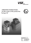
OPERATING INSTRUCTIONS FOR Flow Meters of the series: “VHM in Standard Version“ VSE Volumentechnik GmbH Hönnestraße 49 58809 Neuenrade/Germany Phone + 49 (0)23 94 /616 30 Fax + 49 (0)23 94 /616 33 E-Mail [email protected] Internet www.vse-flow.com 1 Table of Contents Page Important basic information. . . . . . . . . . . . . . . . . . . . . . . . . . . . . . . . . . . . . . . . . . . . . . . . . . . . . . 3 Functional description of the flow meter. . . . . . . . . . . . . . . . . . . . . . . . . . . . . . . . . . . . . . . . . . . . 4 General description. . . . . . . . . . . . . . . . . . . . . . . . . . . . . . . . . . . . . . . . . . . . . . . . . . . . . . . . . . . . 4 Flow Meter Selection . . . . . . . . . . . . . . . . . . . . . . . . . . . . . . . . . . . . . . . . . . . . . . . . . . . . . . . . . . 4 Declaration of Conformity. . . . . . . . . . . . . . . . . . . . . . . . . . . . . . . . . . . . . . . . . . . . . . . . . . . . . . . 4 General requirements for operation. . . . . . . . . . . . . . . . . . . . . . . . . . . . . . . . . . . . . . . . . . . . . . . 4 Maximum operating pressure. . . . . . . . . . . . . . . . . . . . . . . . . . . . . . . . . . . . . . . . . . . . . . . . . . . . 5 Statement to EU-Directive 97/23/EG, Pressurized Devices . . . . . . . . . . . . . . . . . . . . . . . . . . . . 5 Flow measurement range. . . . . . . . . . . . . . . . . . . . . . . . . . . . . . . . . . . . . . . . . . . . . . . . . . . . . . . . 6 Installing the flow meter. . . . . . . . . . . . . . . . . . . . . . . . . . . . . . . . . . . . . . . . . . . . . . . . . . . . . . . . . 6 Cleaning and rinsing the pipes before operating. . . . . . . . . . . . . . . . . . . . . . . . . . . . . . . . . . . . . 7 Preamplifier. . . . . . . . . . . . . . . . . . . . . . . . . . . . . . . . . . . . . . . . . . . . . . . . . . . . . . . . . . . . . . . . . . . 7 General information. . . . . . . . . . . . . . . . . . . . . . . . . . . . . . . . . . . . . . . . . . . . . . . . . . . . . . . . . 7 The single pick-up. . . . . . . . . . . . . . . . . . . . . . . . . . . . . . . . . . . . . . . . . . . . . . . . . . . . . . . . . . . 7 The dual pick-up . . . . . . . . . . . . . . . . . . . . . . . . . . . . . . . . . . . . . . . . . . . . . . . . . . . . . . . . . . . . 7 Application with directional detection. . . . . . . . . . . . . . . . . . . . . . . . . . . . . . . . . . . . . . . . . . . . . 8 Output circuits for the various types of preamplifiers. . . . . . . . . . . . . . . . . . . . . . . . . . . . . . . . . . 9 Custom solutions. . . . . . . . . . . . . . . . . . . . . . . . . . . . . . . . . . . . . . . . . . . . . . . . . . . . . . . . . . . . . . 10 Maintenance and repair . . . . . . . . . . . . . . . . . . . . . . . . . . . . . . . . . . . . . . . . . . . . . . . . . . . . . . . 10 Maintenance and repair of devices . . . . . . . . . . . . . . . . . . . . . . . . . . . . . . . . . . . . . . . . . . . . . . 10 Technical data for the VHM flow meter. . . . . . . . . . . . . . . . . . . . . . . . . . . . . . . . . . . . . . . . . . . 11 Dimensions for VHM flow meter . . . . . . . . . . . . . . . . . . . . . . . . . . . . . . . . . . . . . . . . . . . . . . . . . 11 Dimensions for AHM mounting plates.. . . . . . . . . . . . . . . . . . . . . . . . . . . . . . . . . . . . . . . . . . . . 12 Type code for VHM, AHM. . . . . . . . . . . . . . . . . . . . . . . . . . . . . . . . . . . . . . . . . . . . . . . . . . . . . . 13 Technical data for VII*-*S**/N; VTI*-*S**/N single pick-ups. . . . . . . . . . . . . . . . . . . . . . . . . 14 Electronic connection data for VII*-*S**/N; VTI*-*S**/N single pick-ups. . . . . . . . . . . . . . . 15 Technical data for single pick-ups VEI*-*S**/N single pick-ups. . . . . . . . . . . . . . . . . . . . . . . . 16 Technical data for dual pick-ups VDI*-*S**/N dual pick-ups. . . . . . . . . . . . . . . . . . . . . . . . . . 16 Electronic connection data for VEI*-*S**/N single pick-ups; VDI*-*S**/N dual pick-ups . . . . 17 Type code – signal pick-ups . . . . . . . . . . . . . . . . . . . . . . . . . . . . . . . . . . . . . . . . . . . . . . . . . . . . 18 Technical data for VHM-Titan. . . . . . . . . . . . . . . . . . . . . . . . . . . . . . . . . . . . . . . . . . . . . . . . . . . 19 Dimensions for VHM-Titan. . . . . . . . . . . . . . . . . . . . . . . . . . . . . . . . . . . . . . . . . . . . . . . . . . . . . . 19 Type code for VHM-Titan. . . . . . . . . . . . . . . . . . . . . . . . . . . . . . . . . . . . . . . . . . . . . . . . . . . . . . 20 Technical data for single pick-ups VRI*-*S**/N; VWI*-*S**/N for VHM Titan. . . . . . . . . . . 21 Electronic connection data for single pick-ups VRI*-*S**/N; VWI*-*S**/N for VHM Titan. . . 21 Type code - signal pick-ups for VHM Titan. . . . . . . . . . . . . . . . . . . . . . . . . . . . . . . . . . . . . . . . 22 2 Important basic information Dear customer, dear user, These installation and operating instructions should provide you with the information you need to properly install and commission the flow meter. The installation, commissioning and testing are to be performed by trained and qualified personnel only. These operating instructions must be read and applied carefully to ensure proper, trouble-free and safe operation of the flow meter. VSE is not liable for any damage incurred resulting from not complying with the instructions in this operating instruction. It is not permitted in any case to open the device. These operating instructions for the flow meters of the series ”VHM in Standard-Version” from VSE must be stored, so that they can be read by the group of authorized personnel at any time. Chapters may not be taken of these instructions at any time. A missing operating instructions manual or missing pages must be replaced immediately. VSE can supply you with new instructions or you can download the operating instructions from the internet (www.vse-flow.com). The operating instructions must be given to each subsequent user of this product. Legal information This document is not managed by an updating service of VSE Volumentechnik GmbH. Changes to this document may be made without notice. VSE Volumentechnik GmbH does not provide any implicit guarantees of commercial qualities and suitability for a specific purpose. If the device has been opened, modified or incorrectly connected to the electrical circuits, the guarantee of VSE Volumentechnik GmbH for safe operation is void. VSE Volumentechnik GmbH is not liable in any way for personal injuries or damage to goods resulting from improper installation or improper operating of the flow meter. 3 Operating Instructions – No.: E060044 (E) • Functional description of the flow meter Flow meters from the VSE Volumentechnik GmbH measure the volumetric flow of fluids using the gear method. The two gears in the meter are put in motion by the fluid flowing through the flow meter. The motion of each tooth of the gear is measured by a single or dual signal pick-up that is securely mounted to the flow meter. When the gear rotates, each signal pick-up generates a digital output signal, when a tooth of the gear passes through the detection area. Each time a tooth passes, the single signal pick-up generates one signal, or in case of a dual pick-up, 2 or 4 electrical output pulses, depending on the jumper settings. The gap between the teeth and the housing encloses a volume of fluid, that is transported out, when the gear rotates. This volume of fluid displaced by one gap / tooth mesh, is called the measurement volume V. This measurement volume Vm determines the value of the pulse depending on the size of the flow meter. Vm (l/Imp.) = 1/K-Factor The signal frequency of the output pulse is processed in the electronics receiving the signal and is proportional to the speed of gear rotation and the flow rate. The flow rate corresponds to the volume transferred, which is measured continuously by electronically counting the output pulses. • General description Please follow all instructions in this operating manual; only this guarantees a trouble-free operation of the flow meters. VSE is not liable for any damage ensuing from non-following of these instructions. Opening the devices during the term of guarantee is only authorised after consultation and approval of VSE. • Flow Meter Selection The right choice (rating) of type and size of the flow meter is the deciding factor for the trouble-free and safe operation. Due to the wide variety of applications and flow meter versions, the technical data provided in the VSE catalogs are of a general nature. Certain properties of the devices depend on type, size and measurement range, as well as on the fluid to be measured. Please contact VSE for exact type and size specifications. • Declaration of Conformity “VHM“ series flow meters are tested for their electromagnetic compatibility and noise emission according to the EMC regulations, and meet the requirements of the applicable, legally required EMC directives. They cannot be operated independently. They must be connected to a power source via cable, and they output digital signals for electronic processing. There is a declaration of conformity available for all flow meters. Since the EM-compatibility of the overall measurement system also depends on the routing of cables, on proper connection of the shiel- ding and on every device connected to the system. It must be ensured that all components meet the requirements in the EMC guidelines and that the electromagnetic compatibility of the entire system, machine or plant is guaranteed. All flow meters are tested according to the applicable, legally required EMC directives EN 55011 and EN 61000 and are CE-certified. The label for EC conformity is the CE symbol, which is placed on all flow meters. • General requirements for operation Before installation or operation, you must check the following properties of your system and take the following aspects and corresponding conditions in your system into account for trouble-free and safe operation of the system. 1. The medium to be processed Is the flow meter suitable for the medium? Is the medium viscous or abrasive? Is the medium dirty or is there contamination and suspended particles in the medium? What is the size of the particles of the solid material and could they block the meter? Are there any fillers or other additives in the medium? Is it necessary to install a hydraulic filter before the meter? Are the pipelines clean and free of scraps left over from the installation such as shavings or weld splatter? Is the tank clean and can any foreign material escape from of the tank and into the pipeline system? Is the type of medium changed often and is the system thoroughly rinsed after changing? Has all air been completely bled from the pipes and the overall system? Which types of cleaners are used? Can the seals withstand the cleaning agents and medium? Are the seals suitable for use with the medium to be measured (compatible with the seals)? 4 2. Hydraulic properties of the system Is the maximum operating pressure of the system lower than the maximum permissible operating pressure of the flow meter? Is the maximum pressure drop Δp (on the flow meter) below the maximum permissible pressure drop? Does an exessively great pressure drop Δp occur on the flow meter at maximum flow (e.g. with high viscosity)? Does the flow range of the flow meter (depending on viscosity) correspond to the provided flow? Note that the flow rate range is reduced at high viscosities! Does the temperature range of the flow meter correpond to the provided maximum temperature of the medium? Is the pipe cross-section large enough and are there any large pressure drops in the system? Are the hydraulic connections (supply and return) correctly connected and sealed? Does the pump have enough power to operate the system? A blocked flow meter can stop the flow throughout the system. Is an overpressure valve / bypass provided in the system? 3. Electronic processing and electrical safety Have you selected the best possible flow meter and is it equipped with the proper preamplifier? Does the power supply voltage of the flow meter correspond to the provided voltage? Is the supply voltage provided by the power supply or signal processor sufficiently steady? Does the power supply output the required amount of power? Was the electrical connection wired according to the connection diagram provided? Is the cable shielding connected to the ground conductor? Is there an equalizing conductor connecting the flow meter to the signal processor to eliminate any voltage differences between them? Is the flow meter securely connected to the grounded PE conductor? Is the measuring unit of the flow meter isolated from the grounded PE conductor (e.g. connected using a sleeve)? If it is isolated, then the measuring unit must be connected to the grounded PE conductor! Is there a continuous connection from the cable shielding (grounded PE conductor) through the housing and the 4-pin round plug to the measuring unit of the flow meter? Is the cable routed to prevent interference and can any stray pulses be coupled? Is the 4-pin round plug of the connecting cable screwed tightly to the connector on the flow meter? Are the wires on the signal processor correctly and properly connected? Does the overall system conform to the electromagnetic compatibility (EMC) directives as required by law? Are you following all locally applicable regulations, applicable rules, guidelines and basic requirements for EMC? Systems in which a malfunction or failure can lead to personal injury are to be equipped with suitable safety equipment. The function of this safety equipment is to be checked at regular intervals. • Maximum operating pressure Before installing the flow meter, you must make sure that the maximum operating pressure of the system does not exceed the maximum permissible operating pressure of the flow meter. Please also note the peak pressures can arise, when operating the system. Important: The maximum operating pressure for flow meters in the “VHM“ series is 250 bar / 3600 psi and for „VHM Titan“ series it is 10 bar / 145 psi! • Statement to EU-Directive 97/23/EG, Pressurized Devices VSE flow meters are pressurized devices according to article 1, paragraph 2.1.4. of above mentioned directive. Therefore they are subject to the regulations to this directive. According to article 3, paragraph 1.4, VSE flow meters have to conform with the technical requirements of the guideline. The fluids to be measured are belonging in most of all cases to the class 2, defined in article 9, paragraph 2.2. VSE flow meters do not reach the limit values as defined in article 3, paragraph 1.1. The technical requirements for VSE flow meters therefore are limited to the parts indicated in article 3, paragraph 3. It means the devices have to be designed and manufactured in conformity with acknowledged engineering, such as practiced in one of the member states. This is herewith confirmed. Beside this, the paragraph declares that these devices must not have a CE-marking according to Directive 97/23/ EG. Therefore we do not issue declarations of CE and our products are not labelled acc. to 97/23/EG. 5 • Flow measurement range The flow measurement range (Qmin – Qmax) of the flow meter specified in the data sheet is based on a test medium consisting of hydraulic oil with a viscosity of 21 mm2/s at a temperature of 20°C. For the measurement range with viscosities > 10 mm2/s, VSE specifies a measuring accuracy of up to 0.5% of the measured value and a repeat accuracy of 0.5%. For viscosities from 1 to 10 mm2/s, a measuring accuracy of up to 1.0% of the measured value and a repeat accuracy of 0.5% is specified. Important: Make sure that the maximum permissible operating pressure specified for the flow meter cannot be exceeded in any operating mode of the system. Note the flow range of the flow meter, which depends on the viscosity of the medium to be measured. • Installing the flow meter The flow meter should be installed in a location with easy access so that it can be easily removed to clean the gears. Since flow meters can operate in any mounting position and any direction of flow, you can mount them at any location you want in your system. When installing the flow meter you must make sure that there is always some fluid remaining in the flow meter and that it can never run dry, even when the system is not in operation. For this reason, the outlet of the flow meter should always be under a slight pressure since this firmly fixes the measuring unit of the flow meter in the fluid column (the measuring unit is supported in this fashion by the fluid column) and the pipeline cannot drain empty. In critical cases or when the pipe line is at standstill or standby and can run empty, it is strongly recommended to install an additional non-return valve in the outlet line. non-return valve flow meter tank Figure 1: Flow meter with backpressure Important: Make sure that both the inlet and outlet of the measuring unit of the flow meter is always completely full and that there is some pressure on the outlet. This prevents the creation of gas bubbles and the destruction of the measuring unit, by a sudden and steep increase of flow and at the same time improves measurement accuracy. Block mounting: The flow meter is mounted on a subplate. The subplate is installed in the pipe and is equipped with all hydraulic connections and mounting holes required for mounting the flow meter. Series “VHM“ flow meters can be mounted with screws on a mounting plate installed in the pipe. Whenever possible, you should choose large diameter pipes for the piping system and large diameter lines for the hydraulic supply and return. This reduces the effect of a pressure drop and lowers the flow rate in the overall system. VSE supplies subplates with various pipe thread sizes and with mounting holes on the side or back for all flow meters in the “VHM“ series. Depending on the present conditions, the installed pipe, the pipe diameter or the type of pipe thread, the user can choose the appropriate subplate and install it in the system or machine without requiring any reduction fittlings. The flow meter is screwed onto the subplate using pan head screws. Tighten the screws by hand as tight as they will go first. In special cases, the flow meter can also be mounted directly in the pipe. 6 Important: When mounting the flow meter, you must make absolutely sure that the seals are not damaged in any way and are seated correctly in the hydraulic connections of the flow meter. Incorrectly installed or damaged seals can result in leakage and a leaky system, which can have significant consequences in certain cases. The yellow plastic stoppers in the hydraulic connections of the flow meter protect the measuring unit from dirt and contamination, when the flow meter is placed in storage or for transportation purposes. You must remove these stoppers so that the inlet and outlet are unplugged and open before you mount the flow meter. • Cleaning and rinsing the pipes before operation Before you operate the flow meter, you must carefully clean and rinse the entire system so that no foreign particles can get into the measuring unit of the flow meter, when it is being installed. Foreign particles can block the measuring unit and damage it so badly that the flow meter is unable to supply any valid measurement values any more and must be sent in for repair. After completion of the system or installation of the piping, you must carefully clean and rinse the entire piping system and the tank first. The flow meter must be removed from the piping system. Use a rinsing agent that is compatible with the medium to be used later during operation and will not cause any undesired reactions. You can obtain the corresponding information from your supplier, the manufacturer of the medium or from VSE. Flow meters are measuring sensors manufactured to high precision. They have a mechanical measuring unit consisting of two gears fit tightly with small gaps between them and the housing. Even the least damage to the gears or bearings will cause a measurement error. For this reason, you must always make sure that no foreign particles can get into the measuring unit and that the medium being measured is always completely free from contamination. Once the system has been thoroughly rinsed and there are no foreign particles in the piping system, you can mount the flow meter and start operations. Important: Please clean the pipes and the tank thoroughly since foreign particles and residue can get into the measuring unit and block it or even destroy it. • Preamplifier General information The preamplifiers are supplied in different versions depending on the type of application. Single and dual pick-ups are available. The basic method used to sense and measure, though, is the same for both versions and is based on the carrier frequency principle. When a dual pick-up is used, you simply double or quadruple the number of pulses received depending on the setting. The single pick-up The single pick-up operates with a carrier frequency oscillator that is modulated whenever a tooth passes by. This modulation is evaluated by the subsequent preamplifier electronics and generates a modulated digital pulse proportional to the volume delivered. The number of pulses is proportional to the volume delivered. The flow rate can be derived from the frequency of this pulse signal. The dual pick-up The dual pick-up operates with two independent carrier frequency oscillators that are modulated whenever a tooth passes by. The electronics generates a pulse signal for each modulation. The pulses from both pickup systems are combined in the subsequent preamplifier electronics and output as a double pulse. If necessary, you can select pulse quadrupling by changing the internal code (resetting a jumper), although the max. flow range is thereby reduced. The volume of fluid transported and the flow rate can be derived from the number of pulses and the frequency. 7 Figure 2: Signal output of the preamplifier • Application with directional detection If it is necessary to detect the flow direction, then the flow meters are operated by two single pick-ups type VII*-*S**/N and VTI*-*S**/N. The two single pick-ups are set up with a mechanical phase offset of 90° with respect to the tooth flank sequence. To prevent the signals of two single pick-ups from interfering with each other, you should select pick-ups with two different carrier frequencies, i.e. one with a normal carrier frequency (VII*-*S**/N) and one with a modified carrier frequency (VTI*-*S**/N). The 90° phase offset between the two pulse signals allows you to increase the resolution by processing the rising and falling edges from both channels. Processing the signals in this manner allows for a resolution of 1/4 of the measured volume. Position of piping connection with 2 single pick-ups Single pick-up VTII- .... Single pick-up VIII- .... Flow meter Figure 3: Application with directional detection 8 Mounting plate for side Figure 4: Signal output with two single pick-ups • Output circuits for the various types of preamplifiers There are two versions of single pick-ups available. Single pick-up VII*-*S**/N (VTI*-*S**/N, with modified frequency) and single pick-up VEI*-*S**/N in the round-face housing of the dual pick-up. The single pick-up VII*-*S**/N (VTI*-*S**/N) is placed in a small tube housing so that it can also be used as a sensing system for other applications like turbines, for example. The VII*-*S**/N and VTI*-*S**/N have two transistor outputs for a PNP or NPN output signal (see the wiring diagrams). The preamplifier electronic for operating especially lightweight titanium flow meter is identical to the VII*-*S**/N (VTI*-*S**/N) preamplifier electronic and is labeled with VRI*-*S**/N and VWI*-*S**/N. The single pick-up VEI*-*S**/N and the dual pick-up VDI*-*S**/N in the round-faced housing have an optocoupler transistor in the output for an electrically isolation from the operating voltage of the pick-up. The transistor output can be supplied with voltage using the operating voltage of the flow meter or using a separate power supply. A PNP or NPN output signal is generated depending on the polarity of the power supply voltage on the transistor (see wiring diagrams). The power supply voltage range is Ub = 8 ... 30 V DC. You can operate the preamplifier with any voltage in this specified voltage range (Ub), but make sure that the signal voltage is always adjusted to the power supply voltage. A steady direct voltage with a maximum residual ripple of ± 10% is permitted for the power supply. In all standard versions of the „VHM” series are 2 additional 620 Ω resistors connected in series, in order to limit the current at the transistor output. Important: Please make sure that no extra inductive elements are connected in the power supply of the flow meter, such as contactors, relays, valves, etc. These components are potential sources of interference (especially if the inductive elements are not provided with an adequate protective circuit). They generate high interference pulses, when switched and can interfere with the functioning of the flow meter, although this complies with the electromagnetic compatibility directives. 9 The maximum current per channel is IKmax = 10 mA for an operating voltage > 16 V DC (the current IK depends on the input impedance of the signal processor). The electric connection of the flow meter is performed via the 4-pin round plug located on the preamplifier housing. The connection cable plug is plugged into the plug connection of the flow meter and screwed together. Important: Only use well-shielded cables for the connection cable, with a wire cross section of ≥ 4 x 0.36 mm2 . Please make sure that the housing of the round plug is metallic, containing a connection for the shielding and that the potential of the earth conductor PE is connected to the cable shielding and the housing of the preamplifier. The shielding of the connection cable is connected to the union nut of the plug and is thereby connected to the preamplifier housing and the flow meter. For proper EMC operation of the sensor system, at least one side must be connected to the grounded PE conductor. This connection is usually established by the grounded pipe on the side of the flow meter. You must take care of voltage differences and install potential equalisation, if necessary. VSE supplies a corresponding connection for every type of preamplifier (see pages 15 and 17). The shielding of the cable must be routed continuously up to the flow meter, and may not be interrupted in distribution racks or junction boxes. Route the connection cable directly from the signal processor to the flow meter if possible, as every interruption in the connection is a potential source of error. Important: Voltage differences can arise between the housing of the preamplifier and the earth conductor PE of the signal processor. In this case a potential equalisation ground must be installed (see the wiring diagram)! The maximum length of the cable between the flow meter and the signal processor is approx. 120 m. When long cables are used (approx. 40 m and longer), you must make absolutely sure that the connection cable is routed through an interference free environment. • Custom solutions There are some applications in which you will need a lightweight pick-up, for example. This is often the case in the field of automation. VSE offers custom solutions made of titanium that are especially lightweight. If your application has other requirements, please contact VSE in this regard. VSE has years of experience and can provide solutions quickly to meet special requirements by modifying the mechanical and/or electrical components of existing solutions. • Maintenance and repair VSE flow meters are basically maintenance-free. However, it is recommended to send the flow meters back to the factory at regular intervals for inspection, particularly in difficult applications, when critical media are used (e.g. when using abrasive, contaminating media or media containing fillers or pigments), when high viscosity media are used, or when very heavy strain is placed on the measuring unit (e.g. when the flow changes often and quickly). In this manner, any minor damage can be detected and eliminated early, before the damage leads to total failure during production, whether the failure is caused by a faulty bearing or a blockage of the gears. • Maintenance and repair of devices To ensure fast and economical repair of the flow meters and other components, it is absolutely necessary to include a precise description of the problem or error with the package you send back to VSE. Furthermore, a 10 safety data sheet must also be enclosed in which it is clearly stated, which medium was used with this flow meter and any potential hazards the corresponding medium may attribute. that examination and repair of any flow meter sent to VSE Volumentechnik GmbH will only be performed, when the safety data sheet of the medium used is enclosed and the flow meters have been completely cleaned and rinsed. This serves to protect our employees and makes our job easier. When these instructions are not followed, the package will be returned at the sender‘s expense! The legal regulations relating to occupational safety, accident prevention regulations, regulations relating to environmental protection, waste disposal, and water resources law oblige companies, their employees and other persons, and the environment from harmful effects, when handling hazardous substances. If additional safety precautions are still required in spite of thorough draining and cleaning of the flow meter, then this information must absolutely be enclosed in the package sent back to VSE. Note • Technical data for the VHM flow meter Size Measurement range l/min Measured Volume Vm ml Frequency Hz K-Factor imp./liter VHM 01–1 0.01 … 1 approx. 0.035 approx. 5.0 … 476.0 approx. 30,000 VHM 01–2 0.01 … 1 approx. 0.045 approx. 5.0 … 400.0 approx. 22,000 VHM 02–1 0.05 … 2 approx. 0.120 approx. 6.9 … 278.0 approx. 8,800 VHM 02–2 0.10 … 4 approx. 0.225 approx. 7.4 … 296.0 approx. 4,400 VHM 02–3 0.40 … 8 approx. 0.450 approx. 14.8 … 296.0 approx. 2,200 VHM 03–2 0.50 … 20 approx. 1.010 approx. 8.25 … 330.0 approx. 1,000 The exact data can be found in the calibration report! Measurement accuracy : ± 0.5 % of the measured value (at viscosities > 10 mm2/s) ± 1 % of the measured value (at viscosities 1 – 10 mm2/s) Repeating accuracy : ± 0.5 % under the same operating conditions Materials : Gear housing: Stainless steel 1.4404 Gears: Stainless steel 1.4462 Gear bearings: tungsten carbide Preamplifier housing: Stainless steel 1.4305 or aluminum Gear bearings : Sleeve bushing, ball bearings (optional) Seals : PTFE with FPM core (standard) or PTFE Max. operating pressure : 250 bar / 3600 psi Media temperature : –20°C ... + 120°C (-4°F ... 248°F) (*) Ambient temperature : –20°C … + 60°C (–4°F ... 140°F) (*) Viscosity range : 1 … 20,000 mm2/s Installation position : Any Direction of flow : See direction of the arrow on the flow meter Installation : On the mounting plate with piping connections or as a piping system (custom version) (*) Note the temperature range of the preamplifier as well in this case! • Dimensions for VHM flow meter VHM 01/02 VHM 03 11 Type øA B C D øE F G K L M H Weight kg VHM 01–1 68 29 44 12 4 6 M6 0.760 VHM 01–2 68 29 44 18 5 6 M6 0.750 VHM 02–1 68 29 44 18 6 6 M6 0.740 VHM 02–2 68 34 44 18 6 6 M6 0.860 VHM 02–3 68 43 44 18 6 6 M6 1.075 VHM 03–2 99 50 27 10 25 81 M6 12 2.700 Dimensions are specified in mm • Dimensions for AHM mounting plates AHM 01/02 for side-mounting AHM 03 for side-mounting Position of cable connections Signal pick-up surface surface Flow meter Mounting plate for side mounting Permissible Size VHM 01 – 1 G G 1/8“ G 1/4“ A B C D øE F H øL 68 52 16 20 4 24 M6 9.4 68 52 16 20 6 24 M6 11 M N P O-ring 6.07 x 1.78 G 1/8“ G 1/4“ 01 – 2 02 –1,2,3 1/8“ NPT 7.65 x 1.78 1/4“ NPT G 3/8“ 3/8“ NPT 68 52 100 70 16 20 6 35 M6 11 10 35 M6 15.5 G 3/8“ 03 G 1/2“ 3/8“ NPT 1/2“ NPT Dimensions are specified in mm 12 25 81 13.5 12.42 x 1.78 • Type code for VHM, AHM VHM flow meter AHM mounting plate Series (Modification Id. no.) Version Standard Special version Connection thread G 1/8 G 1/4 G 3/8 G 1/2 1/8 NPT 1/4 NPT 3/8 NPT 1/2 NPT Connection position side Side connection Material V2A Below connection V4A Size VHM 01 VHM 02 VHM 03 13 • Technical data for VII*-*S**/N, VTI*-*S**/N single pick-ups Supply voltage Ub = 8 … 30 V DC ±10% Current consumption (idle) Ib = ca. 4 mA (bei 30 V DC) Signal output circuit Transistor with series resistor R = 2 x 620 Ω PNP and NPN selectable PNP signal output High Signal: US = Ub -1 V; IS = 10 mA max. NPN signal output Low Signal: US = 0 V; IS = 10 mA max. Signal switching frequency 3 Hz – approx. 1000 Hz (*) Electrical connection VSE standard connector M 12 Medium temperature -20°C … +120°C (-4°F … 248°F) Ambient temperature -20°C … +60°C (-4°F … 140°F) Material Stainless steel 1.4305 Weight 115 g (*) Depends on the VHM flow meter size 14 Signal pick-up Flow meter Mounting plate for side mounting • Electronic connection data for VII*-*S**/N, VTI*-*S**/N single pick-ups 15 • Technical data for VEI*-*S**/N single pick-ups Supply voltage Ub = 8 … 30 V DC ±10% Current consumption (idle) Ib = approx. 2.5 mA (idle motion, Ub = 30 V DC) Signal output circuit Transistor with series resistor R = 2 x 620 Ω PNP and NPN selectable by external connection PNP signal output High Signal: US = Ub -1 V; IS = 10 mA max. NPN signal output Low Signal: US = 0 V; IS = 10 mA max. Signal switching frequency 3 Hz – approx. 500 Hz Electrical connection VSE standard connector M 12 Medium temperature -20°C … +85°C (-4°F … 185°F) Ambient temperature -20°C … +60°C (-4°F … 140°F) Material Anodized black aluminum stainless steel 1.4305 (coil) Weight 165 g • Technical data for VDI*-*S**/N dual pick-ups Power supply voltage Ub = 8 … 30 V DC ±10% Current consumption (idle) Ib = ca. 4 mA (bei 30 V DC) Signal output circuit Transistor with series resistor R = 2 x 620 Ω PNP and NPN selectable by external connection PNP signal output High Signal: US = Ub -1 V; IS = 10 mA max NPN signal output Low Signal: US = 0 V; IS = 10 mA max Signal switching frequency 6 Hz – 500 Hz (pulse doubling) (*) 12 Hz – 500 Hz (pulse quadrupling) (*) Electrical connection VSE standard connector M 12 Media temperature -20°C … +85°C (-4°F … 185°F) Ambient temperature -20°C … +60°C (-4°F … 140°F) Material Anodized black aluminum Stainless steel 1.4305 (coil) Weight 165 g (*) Note that the flow measurement range is limited due to the quadrupling pulse mode 16 • Electronic connection data for VEI*-*S**/N single pick-ups, VDI*-S**/N dual pick-ups 17 • Type code - signal pick-ups * With the VDB series... (fiber-optic output), the signal can only be doubled (pulse x 2) 18 • Technical data for VHM-Titan Size Measurement range l/min Measured Volume Vm ml Frequency Hz K-Factor imp./Liter VHM 01–1_T1 0.01 … 1 approx. 0.04 approx. 5 … 417 approx. 24,000 VHM 02–2_T1 0.05 … 2 approx. 0.11 approx. 7.6 … 303 approx. 8,800 The exact data can be found in the calibration report! Measurement accuracy : ± 0.5 % of the measured value (at viscosities > 10 mm2/s) ± 1 % of the measured value (at viscosities 1 – 10 mm2/s) Repeating accuracy : ± 0.5 % under the same operating conditions Materials : Gear housing: Titanium Gears: Stainless steel 1.4462 Gear bearings: tungsten carbide Preamplifier housing: Aluminum (Al Mg 4.5 Mn 0.7) Gear bearings : Sleeve bushing Seals : PTFE with FPM core or PTFE Max. operating pressure : 10 bar / 145 psi Media temperature : –20 … + 85°C (–4°F … 185°F) (*) Ambient temperature : –20 … + 60°C (–4°F … 140°F) (*) Viscosity range : 1 … 20,000 mm2/s Installation position : Any Direction of flow : See direction of the arrow on the flow meter Installation : Block mounting Protection class : Block mounting (*) Please also note the temperature range of the preamplifier in this case! • Dimensions for VHM-Titan Flow meter with preamplifier VHM 01-22TS1/1. + V.L. - 01S00/. Preamplifier VRLI – 01800 / N Standard Ex intrinsically safe VWLI – 01S00 / N Standard Ex intrinsically safe Flow meter VHM – 01-22TS1/1 N Standard S Special shaft D D-Shaft 19 Flow meter with preamplifier VHM 02-12TS13/1. + V.L. - 02S00/. Preamplifier VRLI – 02S00 / N Standard Ex intrinsically safe VWLI – 02S00 / N Standard Ex intrinsically safe Flow meter VHM – 02-12TS13/1 N Standard S Special shaft D D-Shaft • Type code for VHM-Titan Flow meter VHM-Titan 20 • Technical data for single pick-ups VRI*-*S**/N; VWI*-*S**/N for VHM Titan Supply voltage Ub = 8 … 30 V DC ± 10 % Current consumption (idle) Ib = approx. 4 mA (idle motion, Ub = 30 V DC) Signal output circuit Transistor with series resistor R=2 x 620 Ω PNP and NPN selectable PNP signal output High Signal: Us = Ub -1 V; Is = 10 mA max. NPN signal output Low Signal: Us = Ub 0 V; Is = 10 mA max. Signal switching frequency 3 Hz – approx. 1.000 Hz (*) Electrical connection VSE standard connector M12 Medium temperature -20°C … +85°C (-4°F … 185°F) Ambient temperature -20°C … +60°C (-4°F … 140°F) Material AI Mg 4.5 Mn 0.7 Weight 125 g (*) depends on flow meter size • Electronic connection data for single pick-ups VRI*-*S**/N; VWI*-*S**/N for VHM Titan 21 • Type code – signal pick-ups for VHM-Titan 22 24 10/08 www.plakart.de VSE Volumentechnik GmbH Hönnestraße 49 58809 Neuenrade/Germany Phone + 49 (0)23 94 /616 30 Fax + 49 (0)23 94 /616 33 E-Mail [email protected] Internet www.vse-flow.com