1
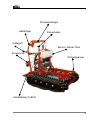
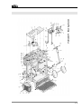
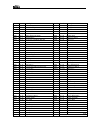
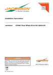
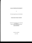
Operating Instructions
for
HY 20-11
NIKO GmbH Maschinen- & Fahrzeugbau . Im Mühlgut 1 . D-77815 Bühl-Weitenung
Preface
Dear customer,
We would like to thank you for your confidence in purchasing a NIKO-product.
We have done our best to provide you with a performance oriented and dependable product.
We ask you to please read the operating instructions carefully before starting up the machine, and to observe
all the instructions. The operating instructions will give you detailed information about operation
and valuable information about startup, maintenance, and service.
As you know, the warranty does not cover any claims resulting from operating error or inappropriate use.
When ordering spare parts, accessories, or when submitting complaints, please include the following data:
Type:
HY 20-11
Machine No:
Year of Build:
Technical Improvements:
We are always trying to improve our NIKO-products. We therefore reserve the right to implement all
improvements and changes we deem necessary to our products, without further announcement, and
without obligation of updating machines already sold.
We are glad to answer any further questions you may have and wish you lots of fun with your new NIKOproduct.
Best regards,
N I K O
Maschinen- & Fahrzeugbau
Serr Dieter, General Manager
NIKO GmbH Maschinen- & Fahrzeugbau . Im Mühlgut 1 . D-77815 Bühl-Weitenung
Table of Contents
•
Product Description
1.)
Appropriate Use
2.)
Assembly
3.)
Functional Description
4.)
Technical Data
Spare Parts Lists
5.)
EC-Conformity Declaration
•
General Safety Information
1.)
Operator Care
2.)
Description of Safety Symbols
•
Transport
1.)
Dimensions and Weight
2.)
Dependable Transport Devices and Aids
3.)
Transport to the Operating Site
•
Startup
•
Operation
1.)
Operator Working Area
2.)
Operation
•
Maintenance
1.)
Cleaning and Lubrication
2.)
Service
•
Help with Breakdowns
•
Machine Data
NIKO GmbH Maschinen- & Fahrzeugbau . Im Mühlgut 1 . D-77815 Bühl-Weitenung
Product Description
This special machine was built for use on inclines, in swampy areas, and uneven and difficult to reach areas.
The application starts where others have already stopped: At an inclination of 30 % – 65 %, depending on the
ground conditions!
It’s low weight, minimal ground pressure ( easy on the ground surface ), the ease in handling and work safety
are baffling. All accessory units are hydraulic driven.
1. Appropriate Use
The hydrostatic Mini-Caterpillar HY 20-11 is exclusively intended for the following use:
- For driving on uneven ground and on steep inclines.
The machine is not intended for any other purpose than described above –
any other use is considered inappropriate use.
We especially note here that it is prohibited to
-
drive on macadamized surfaces for extended periods of time
drive in street traffic
install foreign accessory units. Only NIKO-accessory units may be used.
Observe all technical data.
2. Assembly
Sicherheitsbügel
Haltebügel
Steuerhebel
Schnellspanner
Safety bar
Holding bar
Control lever
Fast tensioner
Benzin/Diesel-Tank
Knieschoner
Haltegriff
Verstellbarer Fußtritt
Fuel/diesel tank
Knee protector
Holding grip
Adjustable foot step
1
Sicherheitsbügel
Haltebügel
Steuerhebel
Haltegriff
Benzin/ Diesel-Tank
Knieschner
Schnellspanner
Verstellbarer Fußtritt
2
Oil fill pipe
with Oilstick
Tensioning leverfor
accessory units
Oiltank
Gear-pump and
axial-flow pumps
Fast Tensioner 3-Point
Oil-engine with brake
Hydraulic cylinder
for unit lifting
3
Hydrauliksteuerventil
für Verstellb. Fußtritt
Hydrauliksteuerventile
für Geräteaushebung
Sicherheitsbügel
(Totmannschaltung)
Steuerhebel
Gashebel
Haltebügel
Luftfilter
3-Wege-Hahn
Ölkühler
Knieschoner
Benzinmotor
Zündschloss
Handstarteinrichtung
Unterbrechungsknopf
Ölfilter
Fußtritt
4
3. Functional Description
Startup Procedure
Pull the choke lever on the engine when the engine is cold, in driving direction to the left and turn the ignition
key clockwise. As soon as the engine starts up, the choke can first be reduced, then released completely.
Once the engine is warmed up it is not necessary to pull the choke, but the interrupt button has to be
activated.
Driving the Caterpillar
After the engine has started up, first slightly pull in the safety bar so that it is located between both dead man
buttons, then the control lever can be operated.
•
•
•
•
•
•
Pull lever B in far enough to free up both switches (approx. halfway).
Move lever A in driving direction and adjust the driving speed.
Pull lever B up to the stop (cruise control).
Now only the left/right direction can be adjusted with lever A.
To newly adjust driving direction and speed, bring lever B to center position.
When lever B is brought to home position, the machine brakes immediately (dead man switch).
(Only use lever C when operating with accessory units)
When the safety bar is released the brake engages immediately (dead man switch), and the caterpillar stops
immediately.
The engine's speed (rpm) can be adjusted with the gas lever.
By pressing the control lever forward or backward the caterpillar moves into the respective direction.
The speed can be varied by moving the control lever.
It can be fixed by pulling the safety and holding levers (cruise control).
Turning the control lever to the left or right changes the driving direction accordingly. This is also possible
when the cruise control is active.
Hydraulic Control Valves
Hydraulic Control Valve for Adjustment of the Foot Step (on Right, in Driving Direction)
By pressing the control valve lever in driving direction, the foot rest and the holding bar lift upward and to the
front, so that it is possible to stand horizontally above the machine when driving uphill. For downhill driving the
foot step has to be moved to the initial position by pulling the control valve lever back.
Hydraulic Control Valve for Hydraulic Unit Lifting (Moving)
By pulling the control valve lever against driving direction the accessory units can be lifted up, by pulling the
lever into driving direction they can be lowered.
When fertilizer spreader or turbo-sprayer with movable frames are attached, the units are shifted to the front
or the rear.
3-Way Shut-Off valve with Hydraulic Connections
For oil supply of hydraulically driven accessory units, such as leave cutter, fertilizer spreader, stacker, and rod
brush.
Only activate shut-off valve when accessory units are used ( lever C, see diagram on previous page).
For this, please observe the General Safety Guidelines.
5
4. Technical Data
Dimensions
Length:
Width:
Height:
Weight:
•
•
•
•
•
•
•
•
•
•
•
•
•
•
•
•
•
1.66 meters
0.90 meters
1.30 meters
400 kg
Robust frame ( carrying capacity up to 1200 kg )
Hydraulically adjustable foot step
Hydrostatic drive via dual pump, 11 cbm
2 oil engines, 7 hp each
Oil-cell multiple-disk brake
Dual control valve or triple control valve at additional charge
Specialty oil filter with injector
Electro-magnetic brake
Rubber chains 230 x 38 x 72 cm, or alternately 190 x 38 x 72 cm
Special 3-point holder
4-cycle-fuel engine, 20 hp
Dead man switch
Operating hour counter
Odometer
Double-acting stroke cylinder
Oil cooler
Continuous speed 0 – 8 km/h, forward and backward
6
7
Art. No.
Pos. No. Description
50101
Pos. 1
Base frame
50102
Pos. 2
Rubber chain 38x72x200 / 38x72x230
50103
Pos. 3
Chain tensioner M20x200
50104
Pos. 4
Tensioning nut M20
50105
Pos. 5
Spring washer, 16 pcs. Ø25x50x3
50106
Pos. 6
Distributor
50107
Pos. 7
Guide wheel Ø200
50108
Pos. 8
Ball bearing no. 6006 2 RS
50109
Pos. 9
Locking ring DIN 472
50110
Pos. 10
Washer Ø13x37 DIN 9021
50111
Pos. 11
Hex head scew M12x20 DIN 933
50112
Pos. 12
Ball bearing no. 6204 2 RS
50113
Pos. 13
Drive wheel
50114
Pos. 14
Spacer pipe Ø21x25x52
50115
Pos. 15
Washer Ø10.5x30 DIN 9021
50116
Pos. 16
Hex head screw M10x16 DIN 933
50117
Pos. 17
Frame top
50118
Pos. 18
Hex head screw M8x25 DIN 933
50119
Pos. 19
Washer Ø9x50x6
50120
Pos. 20
Chain wheel Z10
50121
Pos. 21
Hex head screw M12x50 DIN 931
50122
Pos. 22
Clamping axle Ø35
50123
Pos. 23
Battery, 12 volt, 20 amp / Varta 52012
50124
Pos. 24
Locking ring A12 DIN 471
50125
Pos. 25
Cu-washer Ø12x16x1 DIN 7603
50126
Pos. 26
Control plate
50127
Pos. 27
Control bolt
50128
Pos. 28
Socket, brass Ø12x16x16
50129
Pos. 29
Safety pin
50130
Pos. 30
Hex head screw M8x20 DIN 933
50131
Pos. 31
Nut M4 DIN 985
50132
Pos. 32
Allen head screw M4x16 DIN 912
50133
Pos. 33
Tensioning lever
50134
Pos. 34
Pressure spring
50135
Pos. 35
Tensioning bolt
50136
Pos. 36
Cylinder
50137
Pos. 37
Bolt
50138
Pos. 38
Hex screw M10x20 DIN 933
50139
Pos. 39
U-traverse
50140
Pos. 40
Solenoid
8
9
Pos.No. Art. No. Description
Pos. 1
50301 Lower frame / foot step
Pos.No. Art. No. Description
Pos. 30
50330 Nut M8 DIN 934
Pos. 2
50302 Upper frame
Pos. 31
50331 Gas lever
Pos. 3
50303 Step
Pos. 32
50332 Control valve
Pos. 4
50304 Washer M8 DIN 125
Pos. 33
50333 Control joint right M8
Pos. 5
50305 Nut M8 DIN 934
Pos. 34
50334 Nut
Pos. 6
50306 Hex head screw M10x50 DIN 33 Pos. 35
50335 Control rods, length 335mm
Pos. 7
Pos. 36
50336 Nut left M8
Pos. 8
50307 Hex head screw M10x75 DIN
933
50308 Washer M10 DIN 125
Pos. 37
50337 Control joint left M8
Pos. 9
50309 Nut M10 DIN 934
Pos. 38
50338 Nut M8 DIN 934
Pos. 10
50310 Pressure spring
Pos. 39
50339 Allen head screw M4x6 DIN 912
Pos. 11
50311 Washer Ø12.5
Pos. 40
50340 Solenoid
Pos. 12
50312 Pin Ø3.5x30
Pos. 41
50341 Solenoid plate
Pos. 13
50313 Safety bar
Pos. 42
50342 Solenoid, mounting plate
Pos. 14
50314 Allen head screw M5x10 DIN 12 Pos. 43
50343 Pin Ø5x25
Pos. 15
50315 Aluminum cover plate
Pos. 44
50344 Aluminum flange with bearing
Pos. 16
50316 Hex head screw M8x55
Pos. 45
50345 Hex head screw M6x16 DIN 933
Pos. 17
50317 Cover housing
Pos. 46
50346 Control lever
Pos. 18
50318 Control button
Pos. 47
Pos. 19
50319 Holding bar, pivotable
Pos. 48
50347 Hex head screw M12x50 DIN
933
50348 Washer M12 DIN 125
Pos. 20
50320 Washer M8 DIN 9021
Pos. 49
50349 Nut M12 DIN 985
Pos. 21
50321 Hex head screw M8x50 DIN 933 Pos. 50
50350 Stroke cylinder
Pos. 22
Pos. 51
50351 Oil cooler
Pos. 52
50352 Hex head screw M6x20 DIN 933
Pos. 24
50322 Hex head screw M10x50 DIN
933
50323 Hex head screw M12x35 DIN
933
50324 Washer M12 DIN 125
Pos. 53
50353 Washer M6 DIN 9021
Pos. 25
50325 Knee protector
Pos. 54
50354 Nut M6 DIN 985
Pos. 26
50326 Washer M10 DIN 125
Pos. 55
50355 Hex head screw M6x65 DIN 933
Pos. 27
50327 Hex head screw M10x50 DIN 33 Pos. 56
50356 Spacer
Pos. 28
50328 Hex head screw
Pos. 57
50357 Fuel tank
Pos. 29
50329 Mounting plate
Pos. 58
50358 Odometer
Pos. 23
10
11
Art. No. Pos. No. Description
Art. No. Pos. No. Description
50201
Pos. 1
V-motor, 2-cylinder
50243
Pos. 43
Leakage oil line
50202
Pos. 2
Aluminum flange
50244
Pos. 44
Leakage oil line
50203
Pos. 3
Washer Ø10.5
50245
Pos. 45
Hydro brake
50204
Pos. 4
Allen head screw M10x30 DIN 912
50245a
Pos. 45a
Brake switch valve
50205
Pos. 5
Fitted key
50245b
Pos. 45b
Hydraulic motor
50206
Pos. 6
Motor clutch, Ø 25 inside
50246
Pos. 46
Double nipple
50207
Pos. 7
Washer Ø10.5
50247
Pos. 47
Brake hose wheel
50208
Pos. 8
Hex head screw M8x25 DIN 933
50248
Pos. 48
Brake hose
50209
Pos. 9
Rubber damper
50248a
Pos. 48a
T-piece
50210
Pos. 10
Allen head screw M5
50249
Pos. 49
Brake hose
50211
Pos. 11
Washer Ø5.5
50250
Pos. 50
Banjo bolt
50212
Pos. 12
Washer Ø10.5
50251
Pos. 51
Brake hose
50213
Pos. 13
Nut M10
50252
Pos. 52
Brake line
50214
Pos. 14
Axial-flow pump APVC-11+11200 Pb4RS1
50253
Pos. 53
Washer Ø8.5
50215
Pos. 15
Connection pipe
50254
Pos. 54
Hex head screw M8x16 DIN 933
50216
Pos. 16
Connection hose
50255
Pos. 55
Oil tank
50217
Pos. 17
Hose nipple DN10 - 3/8"
50256
Pos. 56
O-ring
50218
Pos. 18
Hollow screw
50257
Pos. 57
Oil fill plug Ø1" with oil stick
50219
Pos. 19
Fitting connection RSWV 15l
50258
Pos. 58
Hose nipple DN 16 - ¾"
50220
Pos. 20
Banjo bolt ½"
50259
Pos. 59
Hose clamp Ø16-25
50221
Pos. 21
Pressure hose DN 12 2 S/N motor
50260
Pos. 60
Suction hose DN 16
50222
Pos. 22
Pressure line
50260a
Pos. 60a
Return hose
50223
Pos. 23
Double nipple
50261
Pos. 61
Stud M10x30
50224
Pos. 24
Fitting connection GES 15l ½" double nipple 50262
Pos. 62
Washer Ø8.5
50225
Pos. 25
Pressure line
Pos. 63
Hex head screw M8x16 DIN 933
50226
Pos. 26
Slewing joint
50264
Pos. 64
Washer Ø10.5
50227
Pos. 27
Volume separator
50265
Pos. 65
Nut right
50228
Pos. 28
Suction connection DN 16 - ½"
50266
Pos. 66
Control linkage
50229
Pos. 29
Pressure hose motor
50267
Pos. 67
Nut M8 left
50229a
Pos. 29a Pressure hose motor
50268
Pos. 68
Control linkage
50230
Pos. 30
50269
Pos. 69
Joint M8
50230a
Pos. 30a Double nipple
50270
Pos. 70
Hex head screw M8x20 DIN 933
50231
Pos. 31
Banjo bolt 3/8"
50271
Pos. 71
Extension plate
50232
Pos. 32
Fitting connection RSWV 12l-3/8"
50272
Pos. 72
Safety ring Ø30 outside
50233
Pos. 33
Suction hose DN 10
50273
Pos. 73
Washer Ø30x38x2.5
50234
Pos. 34
Leakage oil line
50274
Pos. 74
Torsion spring Ø3
50235
Pos. 35
Pipe clamp
50275
Pos. 75
Washer Ø8.5
50236
Pos. 36
Leakage oil line
50276
Pos. 76
Nut M8
50237
Pos. 37
Manifold hydraulic oil
50277
Pos. 77
Clutch pump side
50238
Pos. 38
Hose clamp
50278
Pos. 78
Pressure line
50239
Pos. 39
Leakage oil line
50279
Pos. 79
3-way shut-off
50240
Pos. 40
Leakage oil line
50280
Pos. 80
Pressure line
50241
Pos. 41
Leakage oil line
50281
Pos. 81
Return
50242
Pos. 42
Magnetic switch
Double nipple
50263
12
EC-Conformity Declaration
According to II A of EG-Machine Guidelines (89/392/EWG)
The manufacturer:
Hereby declares, that the machine described as
follows:
NIKO GmbH Maschinen- & Fahrzeugbau
Im Mühlgut 1
D-77815 Bühl-Weitenung Germany
NIKO-Climber Type HY 20-11
Machine No.
Complies with the safety and health requirements EC-Machine Guidelines 89/392/EEC
of the following EC-Guidelines:
Version 93/44/EEC
Harmonized standards applied:
DIN EN 292
Safety of machines:
Part 1
Basic definitions, general design guidelines
Part 2
DIN EN 294
DIN EN 349
Technical guidelines and specifications
Safety distances to avoid contact of upper body parts
with dangerous area
Minimum distances to avoid pinching of body parts
Machine safety; emergency-stop device
DIN EN 418
DIN EN 60204
Machine safety; general requirements for electrical
machine equipment
Part 1
:
This conformity declaration is voided by constructive changes, affecting both technical data stated in
the operating instructions and appropriate use, altering the machine significantly!
Bühl, Date
Serr Dieter, General Manager
13
General Safety Information
1. Operator Care
The Caterpillar Hydro 20-11 was constructed and manufactured according to an endangerment analysis and
after careful selection of the harmonized norms to be observed, as well as further technical specifications.
It fulfills state-of-the-art requirements and ensures a maximum of safety.
However, these safety standards can only be maintained in practical use when all necessary measures are
taken. It is the responsibility of the machine operator to plan these measures and monitor their execution.
The operator especially has to make certain, that
-
-
the machine is only used for the intended purpose (see chapter ‘‘Product Description‘‘).
the machine is only operated in faultless and functional condition, and especially, that the functionality of
the safety devices is regularly checked.
personal safety equipment for operating personnel, maintenance personnel, and repair personnel is
available and being used.
the operating instructions are complete and in readable condition, readily available at the machine
operating site.
the machine is only operated, maintained and repaired by qualified and authorized personnel and
that the personnel is instructed regularly as to applicable questions of work safety and environmental
protection and has knowledge of the operationg instructions and, especially, the safety information.
all safety and warning labels remain on the machine, and are in readable condition.
aside from the information in the operating instructions, the generally applicable safety and accident
protection guidelines are observed.
applicable regulations are observed when using official roadways.
before starting work, you know about all devices and control elements, as well as their functions. When
work is already in progress it will be too late for this!
the engine is started only from the driver seat. The engine may not be started by hot-wiring the electrical
connections on the starter, since the machine may start moving immediately.
the clothing of the driver fit tightly. Avoid baggy clothing.
-
Check the immediate area before starting to drive (!!!CHILDREN!!!). Make sure you can see sufficiently!
-
Do not start the engine in closed rooms. (DANGER OF SUFFOCATION)!
-
Take care when handling gasoline – increased danger of fire!!! Never refill gasoline near open flames or
sparks. DO NOT SMOKE while refilling gasoline!!!
-
1
GENERAL SAFETY INFORMATION
1.
-
Operator Care
Before refueling shut down the engine and pull the ignition key. Do not refuel in closed rooms. Wipe away
spilled gasoline immediately (danger of ignition).
To avoid danger of fire, keep machine in clean condition!
Be careful when handling battery acid (POISONOUS & CORROSIVE) !
Check the caterpillar for traffic and operating safety before each startup !
The vehicle may only be operated by persons who are in good physical and mental condition. It is not
allowed to take medication or drink alcohol before operating the vehicle.
The vehicle may not be operated by minors.
It is prohibited to transport passengers!
The driving speed must be adapted to the conditions of the terrain.
When driving on curvy terrain with attached or mounted attachments, the additional length and the
flywheel mass have to be considered!
Secure the caterpillar against rolling, shut down the engine. (By shutting down the engine the hydraulic
brake engages). Pull the ignition key.
Never leave caterpillar unattended as long as the engine is running.
Don’t ever leave the driver seat during operation.
Lower attachments completely before leaving the caterpillar!
Hydraulic fluid leaking at high pressure (gasoline, hydraulic oil) can penetrate the skin and cause serious
injuries. So please consult a physician immediately, otherwise serious infections may result.
The mounting of the chain requires sufficient knowledge and safety precautions.
Check screws and connecting elements for tightness and retighten, if necessary.
The chain needs to be retightened initially after approx. 10 hours, after that when needed.
When working on electric equipment always remove the ground from the battery.
Mount attachments only with the recommended devices.
Only operate the caterpillar when all safety devices are attached and in proper position.
The driving speed always has to be adapted to the terrain.
2. Explanation of Safety Symbols
The following safety symbols are used in these Operating Instructions. The symbols are intended to
specifically make the reader aware of adjacent safety information.
These symbols should make you aware that there is danger to life and personal health.
Caustic Materials
Fire Hazard
Corrosive Materials
Poisonous
Smoking Prohibited
Fire Hazzard
8
Ätzende Stoffe
Caution Children Danger of Suffocation
2
Transport
To avoid machine damage or life threatening injuries during setup of the machine, the following
points absolutely have to be observed:
-
Transport of the machine may only be handled by qualified persons in observance of the safety
information.
The machine may only be lifted using the holding points provided. For transport of the machine only
carrying devices and hardware described here may be used.
Also read the chapter on ‘‘General Safety Information‘‘.
1. Dimensions and Weight
•
•
•
Total length
Total width
Total height
1.66 meters
0.90 meters
1.30 meters
2. Dependable Transport Devices and Aids
The caterpillar can be transported on a pallet with a fork lift.
3. Transport to the Operating Site
The caterpillar gets transported to your site on a truck or trailer.
Startup
To avoid machine damage or life threatening injuries during startup of the machine, the following points
absolutely have to be observed:
-
Assembly and installation of the machine may only be done by qualified persons in observance of the
safety information.
Before first startup, check that all tools and foreign parts are removed from the machine.
Test all safety devices and the emergency-stop switching them on and off before starting with operation.
(Before startup, check the running direction of the motor)
Also read the chapter ‘‘General Safety Information‘‘.
1
Operation
To avoid machine damage or life threatening injuries during operation of the machine, the following points
absolutely have to be observed:
- The machine may only be used/operated for the purpose it is intended for.
- Before startup of the machine, inform yourself about appropriate action in case of breakdown.
- Before startup of the machine, check the functions of the following units:
- Protective covers and
- emergency-stop switch
- Also read chapter "General Safety Information".
1. Operator Working Area
The exclusive work place of the driver is the driver seat.
2. Operation
Basic Rule:
•
Check the caterpillar for traffic and operating safety before every startup.
Transport of persons, passengers, operators:
•
Nobody except the driver himself may be transported
Driving Operation:
•
•
•
The driving speed has to be adapted to the environmental conditions and attachments mounted.
When driving on curvy roads with connected or mounted attachment, the additional length and the
flymass of the attachments have to be observed.
Never leave the driver seat while the vehicle is in operation – danger of accident!
Leaving the Caterpillar
•
•
•
•
•
•
Secure the caterpillar against unintended movement when leaving.
Shut down the engine.
Pull the ignition key.
Never leave the caterpillar unattended while the engine is running.
Never leave the driver seat during operation.
Lower the attachments completely before leaving the caterpillar.
Attachment Units
•
1.
•
•
•
•
•
•
Attachments may only be fastened with the recommended fastening devices.
Only operate the caterpillar when all safety guards are attached and in proper position.
Only NIKO-attachment units may be used. NIKO is not liable for the use of any other attachment.
There is danger of injury when mounting attachments to the caterpillar.
There is danger of being pinched and/or cut in the area of the 3-point system.
Do not step between the caterpillar and the attachment during remote operation of the 3-point system.
It is not allowed to stand between caterpillar and attachment if the vehicle is not secured against rolling
with the locking brake and/or blocks.
When driving curvy roads with connected or mounted attachments also observe the extra length and the
flymass of the attachment.
1
Maintenance and Service
To avoid machine damage or life threatening injuries during maintenance of the machine, the following points
have to be observed under all circumstances:
-
All working steps for maintenance of the machine absolutely have to be conducted in the order listed.
First secure the immediate area for maintenance of the machine.
Shut down all power supplies and secure them against unintended restart.
Shut down all compressed air units.
Only use the operating fuels recommended.
Only use spare parts specifically listed in our spare parts lists.
Also read chapter „General Safety Information“.
1. Cleaning and Lubricating
Clean and lubricate all clutches, plugs, and movable parts after every operation.
2. Service
•
•
•
•
•
•
•
•
•
•
•
•
Check chain tension initially after approx. 10 hours, afterwards at least every 50 hours and adjust, if
necessary.
Retighten lug nuts after 50 operating hours.
Change motor oil after approx. 50 hours.
Change hydraulic oil and filter after approx. 150 hours.
Check or change fuel filter and spark plugs.
Check valve adjustment ( intake 0.10 mm, outlet 0.15mm)
Clean and oil carburetor and steering linkage.
Clean motor oil cooler by freeing it thoroughly from dirt and grass.
Check chain tension and adjust, if necessary.
Check hydraulic connections and hoses for tightness.
Observe the maintenance plan provided by the manufacturer.
Periodically clean motor oil cooler and steering linkage by freeing them thoroughly from dirt and grass.
Briggs & Stratton
Oil filter
Air filter
Air filter, rubber
Spark plugs
No. 492932
No. 394018S
No. 272490S
No. 491055
Hydraulic filter
Oil combination
No. E.084-78
No. 10W-30MC
Engine Maintenance
•
•
•
•
•
•
•
•
•
•
•
Do not perform any maintenance work while the engine is running.
When working on the engine always disconnect the battery (minus position).
Secure the standing caterpillar on inclines using blocks.
Pull the ignition key.
Only refill fuel when the engine is shut off.
Observe the recommended quality of oil and fuel, and store them only in approved containers.
Caution when draining hot oil – danger of scalding!
Dispose of used oil in a responsible manner.
Oil and cooling agent are under pressure – danger of scalding!
Reinstall safety devices after service.
Do not use starter liquid when using electric starter.
2
•
•
The starter liquid is flammable and explosive.
Empty used and apparently empty pressurized spray cans completely in an open area, free of sparks and
flames.
Electrical Equipment
•
•
•
•
•
•
•
When working on the electrical equipment always disconnect the battery (minus position).
Make sure to reconnect in the correct order – first the plus position, then the minus position.
Caution with battery gases – they are highly explosive.
Avoid sparking and open flames, as well as smoking near the battery.
Only use original fuses. Too strong fuses can destroy the electrical equipment.
Activate the starter only for a short time, otherwise the coil will overheat. Let the starter cool down.
Do not weld, drill, saw, or grind on the caterpillar or the safety frame. If damage has occurred, have the
parts replaced.
Attachment Units
•
•
•
•
•
•
•
Before attaching units, bring the 3-point system lever into proper position to avoid unintended raising and
lowering.
There is danger of injury when mounting attachments to the caterpillar.
There is danger of pinching and cutting in the area of the 3-point system.
Do not step between the caterpillar and the attachment during remote operation of the 3-point system.
It is not allowed to stand between caterpillar and attachment if the vehicle is not secured against rolling
with the locking brake and/or blocks.
When driving curvy roads with connected or mounted attachments, also observe the extra length and the
flymass of the attachment.
Attachments may only be fastened with the recommended fastening devices.
Only operate the caterpillar when all safety guards are attached and in proper position.
3
Tensioning Device for Chain Tensioner
4
Help with Breakdowns
To avoid machine damage or life threatening injuries when handling breakdowns of the machine, the
following points must be observed:
- Only attend to a breakdown if you are qualified to do so.
- First secure the machine against unintended restart by ...
- Ensure that the machine can be brought to a safe state by a second person at any time.
- Secure the operating range of moving machine parts.
- Also read chapter „General Safety Information“.
Cause
Remedy
Motor does not start
Check battery, check fuel/diesel, clean or change air
filter
Check hydraulic oil, check hoses, check control lever,
release brake, check brake mechanism, press
interrupt button, read the motor manual
Caterpillar does not move
5
Warranty
NIKO-products are built using modern manufacturing technologies with a maximum of care, subjected to
numerous quality controls.
This is why NIKO offers a 12 months warranty, if the following conditions are met:
1.) The warranty starts at date of purchase.
2.) The warranty includes material and manufacturing defects. For subsupplier parts (hydraulics, electronics,
engine) we are only responsible to the extend of the warranty of the respective subsupplier. During the
warranty period fabrication and material defects are handled free of charge by replacement or refitting of
parts in question. Others, further claims, such as trade, discount, or damage compensation not
concerning the delivered products are explicitly excluded.
Warranty claims are exclusively handled by authorized repair shops, NIKO-manufacturing
representatives, or the manufacturer.
3.) Excluded from the warranty are damages due to wear, soiling, corrosion, and all faults caused by
inappropriate use and its consequences. Also, unauthorized repairs or changes of original conditions void
the warranty. No recovery of damages is possible if spare parts other than original NIKO-parts are used.
Therefore, please pay special attention to the operating instructions. Direct any questions you may have
to our manufacturing representatives or directly to the manufacturer.
Warranty claims have to be submitted to the manufacturer within 30 days form the date of damage.
Please provide the date of purchase and the machine number and use the warranty form provided.
Warranty repairs can only be carried out by an authorized repair shop, after consulting with NIKO. Please
advise your repair shop accordingly.
Repairs done under warranty do not extend the warranty period!
Faulty transport is not a manufacturing fault, and therefore, is not the responsibility of the manufacturer.
4.) Claims for damages other than on the products itself are excluded. This includes liability for damages
resulting from operating error. Unauthorized modifications to the product can lead to damages and
release the shipper from any responsibility for these damages.
6