1
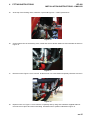
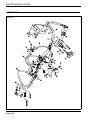
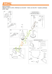
25006G-GB (Rev.3)
Installation Instructions
Jacobsen
GP400 Three Wheel Drive Kit LMAC418
WARNING
WARNING: If incorrectly used this machine can cause severe
injury. Those who use and maintain this machine should be
trained in its proper use, warned of its dangers and should
read the entire manual before attempting to set up, operate,
adjust or service the machine.
GB
United
Kingdom
RJL 100 March 2014
When Performance Matters.™
© 2014, Ransomes Jacobsen Limited. All Rights Reserved
1
2
3
4
5
CONTENTS
GP 400
INSTALLATION INSTRUCTIONS - LMAC418
INTRODUCTION ................................................................................ 4
SAFETY INSTRUCTIONS .................................................................. 8
FITTING INSTRUCTIONS .................................................................. 10
PARTS LIST ...................................................................................... 20
PARTS MANUAL-GP 400
PRODUCT IDENTIFICATION_______________________________________________ _
Machine Serial Plate
A
Maximum front axle load in Kg (for machines being
driven on the highway)
B
Gross weight (mass) in Kg
C
Maximum rear axle load in Kg (for machines being driven
on the highway)
D
Power in Kw
E
Date code
F
Machine type (Designation)
G
Product code
H
Product name
J
Serial number
West Road
Ransomes Europark
Ipswich IP3 9TT
England
A
Kg
B
Kg
F
H
C
E
D
Kw
Kg
G
J
Serial Plate Location
The serial plate is located on the chassis at the rear of the
machine.
Chassis Stamping
The Serial number and date code (A) are stamped on the
chassis rear axle support plate.
A
GY000301
ABCD
ROPS Serial Plate
A
Weight of ROPS
B
Date Code
C
Standard Used
D
Part Number
E
Used on Product
F
Serial Number
West Road
Ransomes Europark
Ipswich IP3 9TT
England
A
B
Kg
C
D
E
F
ROPS Serial Plate Location
The serial plate is located on the ROPS cross beam
between the seat and engine cover.
West Road
Ransomes Europark
Ipswich IP3 9TT
England
A
B
Kg
C
D
E
F
West Road
Ransomes
Ipswich
Europark
England IP3 9TT
A
B
F
Parts- 4
D
E
C
Kg
PARTS MANUAL-GP 400
SPARES STOCKING GUIDE
To keep your equipment fully operational and productive, Ransomes suggests you maintain a
stock of the more commonly used maintenance items. We have included part numbers for
the additional support materials and training aids.
SERVICE SUPPORT MATERIAL
Part No.
Description
Part No.
Description
97898-72020
Kubota Diesel Engine Parts
Manual
MS-2263
Briggs & Stratton Gasoline Engine
Parts Manual
IG689-8916-1
Kubota Diesel Engine Operators
Manual
MS-5156-5/03
Briggs & Stratton Gasoline Engine
Operators Manual
SERVICE PARTS
Part No.
Description
Part No.
Description
5002644
Engine Oil Filter Diesel
492932S
Engine Oil Filter Gas
840352
Air Filter Element Diesel
5000441
Air Filter Element Gas
550489
Fuel Filter Element Diesel
272490S
Air Pre Cleaner Gas
25000G
Safety, Ops and Maintenance
Manual
4199061
Hydraulic Oil Filter Element
Parts- 5
PARTS MANUAL-GP 400
HOW TO USE THE PARTS MANUAL
ITEM NUMBER
Each part which is identified in the illustrations has an item number. Parts which do not have an item
number may not be readily identified in the illustration but are usually closely associated with the
immediately adjacent part.
ASSEMBLIES
A complete assembly, e.g. a wheel motor or hydraulic motor or roll assembly, is listed as a complete
item with subsequent individual components listed separately.
The assembly is listed under it’s part number with component parts being listed offset to the right, e.g:ITEM
4295
4296
4298
4300
4301
4301.1
4301.2
4301.3
4301.4
4301.5
4301.6
4301.7
4301.8
PART NO.
MBG2504
MBG3848
450865
450378
Wl001
008162130
008170390
008161830
008169140
008169150
002993010
008161990
008170780
DESCRIPTION
Bracket
Latch
Screw, M8 X 20, Sckt Csk Hd
Nut, M8 Nyloc
Set Of Wheels
• Wheel & Hub Assy
• • Tyre
• • Rim
• • Hub Assy.
• • Cap
• • Lubricator
• Wheel & Tyre
• • Tyre
QTY
1
2
2
2
1
1
1
1
1
1
1
2
2
REMARKS
(Rear)
(Front)
It may not be possible to illustrate every item. With certain items purchased from outside suppliers
some component parts may not be available from Ransomes and may need to be specially ordered
from the supplier.
QUANTITIES
Quantities shown are for one assembly or sub-assembly.
USING THE PARTS LIST
Determine the function and application of the part required. Turn to the main index page and select the
appropriate section. Locate the part on the illustration and parts list and read off the quantity from the
appropriate MODEL column.
NUMERICAL INDEX
This is a summary of all part numbers used in the manual arranged in numerical sequence and showing the page and item number under which the parts appear.
ORDERING OF SPARE PARTS
When ordering replacement parts, it is most important to quote the SERIAL NUMBER of the machine,
PART NUMBER, DESCRIPTION and QUANTITY required.
Any arbitrary modifications carried out on this machine may relieve the manufacturer of liability for any
resulting damage or injury.
ABBREVIATIONS
N/A Not Available
ARAs Required
Parts- 6
PARTS MANUAL-GP 400
GUIDELINES FOR THE DISPOSAL OF SCRAP PRODUCTS
DURING SERVICE LIFE
Used oil, oil filters and engine coolant are hazardous materials and should be handled in a safe and
environmentally responsible way.
In the event of a fluid leak, contain the spill to prevent it entering the ground or drainage system. Local legislation
will dictate how such spills are to treated.
Following the maintenance procedures laid out in this manual will ensure that the impact the machine has on the
local environment is controlled.
When it has been identified that a turf care product has no further functional value and requires disposal, the
following actions should be taken.
END OF SERVICE LIFE
These guidelines should be used in conjunction with applicable Health, Safety and Environmental legislation and
use of approved local facilities for waste disposal and recycling.
•
•
•
•
•
•
•
•
Position the machine in a suitable location for any necessary lifting equipment to be used.
Use appropriate tools and Personal Protective Equipment (PPE) and take guidance from the technical
manuals applicable to the machine.
Remove and store appropriately:
1. Batteries
2. Fuel residue
3. Engine coolant
4. Oils
Disassemble the structure of the machine referring to the technical manuals where appropriate. Special
attention should be made for dealing with ‘stored energy’ within pressurised elements of the machine or
tensioned springs.
Any items that still have a useful service life as second hand components or can be re-serviced should
be separated and returned to the relevant centre.
Other worn out items should be separated into material groups for recycling and disposal consistent
with available facilities. More common separation types are as follows:
• Steel
• Non ferrous metals
• Aluminium
• Brass
• Copper
•Plastics
•Identifiable
• Recyclable
• Non recyclable
• Not identified
• Rubber
• Electrical & Electronic Components
Items that cannot be separated economically into different material groups should be added to the
‘General waste’ area.
Do not incinerate waste.
Finally update machinery records to indicate that the machine has been taken out of service and scrapped.
Provide this serial number to Ranmsomes Jacobsen Warranty department to close off relevant records.
Parts- 7
3
SAFETY INSTRUCTIONS
GP 400
INSTALLATION INSTRUCTIONS - LMAC418
•
This safety symbol indicates important safety messages in this manual. When you see this symbol, be
alert to the possibility of injury, carefully read the
message that follows, and inform other operators.
3.1 OPERATING INSTRUCTIONS
•
Ensure that the instructions in this book are
read and fully understood.
•
No person should be allowed to operate this
machine unless they are fully acquainted with
all the controls and the safety procedures.
•
Never allow children or people unfamiliar with
these instructions to use this machine. Local
regulations may restrict the age of the
operator.
3.2 SAFETY SIGNS
•
It is essential all safety labels are kept legible,
if they are missing or illegible they must be
replaced. If any part of the machine is
replaced and it originally carried a safety label,
a new label must be affixed to the
replacement part. New safety labels are
obtainable from Ransomes dealers.
3.3 ADJUSTMENTS, LUBRICATION,
MAINTENANCE & CLEANING
•
Stop the engine and make sure all moving
parts are stationary.
•
Apply brakes and disengage all drives.
•
Read all the appropriate servicing instructions.
•
Use only the replacement parts supplied by
the original manufacturer.
•
When adjusting the cutting cylinders take care
not to get hands and feet trapped when
rotating cylinders.
•
Make sure that other people are not touching
any cutting units, as rotation of one cylinder
can cause the others to rotate.
•
To reduce the fire hazard, keep the engine,
silencer and battery compartments free of
grass, leaves or excessive grease.
•
Replace worn or damaged parts for safety.
en-8
•
•
•
•
•
•
•
•
•
•
•
•
•
•
•
•
When working underneath lifted parts or
machines, make sure adequate support Is
provided.
Do not dismantle the machine without
releasing or restraining forces which can
cause parts to move suddenly.
Do not alter engine speed above maximum
quoted in Engine Specification. Do not
change the engine governor settings or
overspeed the engine. Operating the engine
at excessive speed may increase the hazard
of personal injury.
When refuelling, STOP THE ENGINE, DO
NOT SMOKE. Add fuel before starting the
engine, never add fuel while the engine is
running.
Use a funnel when pouring fuel from a can
into the tank.
Do not fill the fuel tank beyond the bottom of
the filler neck.
Replace all fuel tank and container caps
securely.
Store fuel in containers specifically designed
for this purpose.
Refuel outdoors only and do not smoke while
refuelling.
If fuel is spilled, do not attempt to start the
engine but move the machine away from the
area of spillage and avoid creating any source
of ignition until fuel vapours have dissipated.
Allow the engine to cool before storing in any
enclosure.
Never store the equipment with fuel in the tank
inside a building where fumes may reach an
open flame or spark.
If the fuel tank has to be drained, this should
be done outdoors.
Do not spill fuel onto hot components.
When servicing batteries, DO NOT SMOKE,
and keep naked lights away.
Do not place any metal objects across the
terminals.
When Pressure Washing the Mower. Turn the
engine off and remove the starter key.
If the engine has been running, it should be
allowed to cool sufficiently to prevent damage
to the block and exhaust manifold. Never
force water into any electrical components,
3
SAFETY INSTRUCTIONS
GP 400
INSTALLATION INSTRUCTIONS - LMAC418
the air cleaner or exhaust muffler as water
could enter the engine cylinder and cause
damage.
DANGER:
Indicates an imminently hazardous situation which,
if not avoided, WILL result in death or serious injury.
WARNING:
Indicates a potentially hazardous situation which, if
not avoided, COULD result in death or serious injury.
CAUTION:
Indicates a potentially hazardous situation which, if
not avoided, MAY result in minor or moderate injury
and property damage. It may also be used to alert
against unsafe practices.
IMPORTANT:
Transport speed is for highway use only. Never select transport speed on grass areas or uneven or unsurfaced roads or tracks.
en-9
4
FITTING INSTRUCTIONS
GP 400
INSTALLATION INSTRUCTIONS - LMAC418
4.1 PREPARATION
CAUTION: Read the mower’s manual and
become familiar with the mower, the controls and proper use of the equipment.
Stay alert for potential hazards and follow all
safety precautions. Read all instructions
completely and make sure you understand them
before proceeding with the assembly
1.
Park the mower on a flat and level surface, fully lower the implements to the ground, engage parking
brake, stop the engine and remove key from ignition switch.
2.
Wait for all movement to stop before making any adjustments or modifications.
3.
Take this opportunity to thoroughly inspect the equipment and perform other maintenance.
The “Right” and “Left”, “Front” and “Rear” of the machine are referenced from the operator’s right and left when
seated in the operator’s seat facing the direction of forward travel.
4.2 DESCRIPTION
The following instruction details the process of installing the Three Wheel drive kit LMAC418 to the GP 400
machine.
en-10
4
FITTING INSTRUCTIONS
GP 400
INSTALLATION INSTRUCTIONS - LMAC418
4.3 FITTING INSTRUCTIONS
WARNING
• If any part of this instruction is not understood, contact
your Jacobsen dealer for clarification, before proceeding.
• These Instructions will alert you to certain things you
should do very carefully to avoid hurting yourself or others.
CAUTION
Never perform service or maintenance on or near a hot
engine. Always allow ample time for the engine to cool.
Severe burns can result if engine has not been allowed to
cool.
Allow time for the hydraulic oil to cool. Installation of this kit
requires handling of hydraulic oil. Hot hydraulic oil can
cause severe burns.
WARNING
When raising the vehicle for repairs or maintenance,
ALWAYS use jack stands to provide adequate support.
NEVER rely on hydraulic or mechanical jacks for support. If
not supported properly, the vehicle may fall unexpectedly
resulting in serious personal injury or death.
1.
Block the front tyres and raise rear of mower (Figure 1).
Figure 1
en-11
GP 400
INSTALLATION INSTRUCTIONS - LMAC418
4
FITTING INSTRUCTIONS
2.
Remove rear fork and wheel assembly. Retain the wheel and hardware for reinstallation on new fork and
hub assembly.
3.
Install the hydraulic motor, part 008006930, into the new rear fork assembly, part 894728, as indicated in
Figure 2, using the supplied hardware. Tighten the retaining bolts, part 451110346, to approximately 90 113 Nm (67 - 83 ft-lbs). Motor Hub Standard or Castled Nut Torqued to 400-540Nm. Then secure Split Pin
90 – 113 Nm
Figure 2
.
4.
Using previously retained hardware, install the new rear fork assembly. Tighten the lower nut until washer
will not turn by hand, then back off nut until washer will turn freely. Prevent lower nut from turning, then
install and tighten upper nut to 68 Nm (50 ft-lbs).
5.
Using previously retained hardware, install and secure steering cylinder to the rear fork.
6.
Install two elbows, part W158007-05, into the hydraulic motor, as shown in Figure 3.
Elbows
Figure 3
7.
Install and secure tyre. Tighten retaining nuts to approximately 95 - 140 Nm (70 - 100 ft-lbs).
8.
Lower the mower.
9.
Mount the flushing valve, part 4187320, to the bracket 4268492 (as indicated in Figure 4), using two M8 x
55 bolts, washers and nuts Figure 4.
en-12
4
GP 400
INSTALLATION INSTRUCTIONS - LMAC418
FITTING INSTRUCTIONS
Figure 4
Turn IN one
revolution
Figure 5
10.
Undo the lock-nut on the flushing valve, turn the adjuster IN one revolution and lock the lock-nut Figure 5.
11.
Raise fuel tank frame and secure with support rod A Figure 6.
A
Figure 6
12.
Install and secure the flushing valve bracket to the ROPS rear left bracket on the chassis using M10 x 25
cap screw bolts.
en-13
4
GP 400
INSTALLATION INSTRUCTIONS - LMAC418
FITTING INSTRUCTIONS
13.
Disconnect the case drain tube from the front right wheel motor and install and secure 11/16 ORFS cap,
part 002498400, to the end of the elbow in the motor A Figure 7. Cap the tee piece under the seat B Figure
7 with 11/16 ORFS cap, part 002498400.
14.
Disconnect the hose A Figure 8 from the T-piece on the pump and remove hose completely from the lower
T-Piece connecting the front 2 wheel motors located underneath the seat plate and discard hose.
15
Remove cap at position B Figure 8 and fit to position C Figure 8
NOTICE
ENSURE fittings are clean to prevent contamination in hydraulic system.
B
A
Fig
ure 7
D
A
A
B
C
Figure 8
B
Figure 9
en-14
4
15.
GP 400
INSTALLATION INSTRUCTIONS - LMAC418
FITTING INSTRUCTIONS
At the top of the flushing valve, install two T-pieces B Figure 9 1” ORFS, part 544071.
B
A
Figure 10
16.
On the bottom face of the flushing valve, install and secure elbows 158007-01 and orientate as shown in
Figure 10.
A
B
C
Figure 11
17.
Remove hose A Figure 11 from cross B. Fit tee from kit C to cross B then temporarily refit hose A to tee C.
A
Figure 12
18.
Replace hose A in Figure 11 from machine completely and by using hose 4250912 supplied within kit
reconnect to tee piece and return tank fitting. Orientate hose to position indicated in Figure 12.
en-15
4
GP 400
INSTALLATION INSTRUCTIONS - LMAC418
FITTING INSTRUCTIONS
A
Figure 13
19.
Install and secure hydraulic hose 4268495, connecting top left T-piece of flushing valve to lower T-piece of
front motor drive piping A, Figure 13.
C
A
B
E
D
Figure 14
20.
Install and secure hydraulic hose 4268494, connecting top right T-piece of flushing valve to lower T-piece
of the pump B, Figure 14.
Figure 15
21.
Remove cap from the upper T-piece on the pump. Install and secure hydraulic hose 4240304 C Figure 16,
connecting the upper T-piece of the pump with the bottom left elbow on the flushing valve A Figure 15.
en-16
4
GP 400
INSTALLATION INSTRUCTIONS - LMAC418
FITTING INSTRUCTIONS
B
A
Figure 16
22.
Secure 11/16 ORFS T-piece D Figures 16, part 002498400, to existing cross. Reinstall and secure original
hose to the end of the T-piece E Figures 16 4147141. Iinstall and secure to connector the T-piece branch
part and connect to bottom
right hand connector B
Figures 17 of the flushing
C
valve.
A
B
E
D
Figure 17
B
A
Figure 18
en-17
4
GP 400
INSTALLATION INSTRUCTIONS - LMAC418
FITTING INSTRUCTIONS
23.
Install and secure these two
hoses, connecting the bottom
elbow on the wheel motor to
the top left T-piece on the
flushing valve and the top
elbow on the wheel motor to
the top right T-piece on the
flushing valve. Secure the
nylon sleeve with cable ties
Figure 18.
24.
Reposition the fuel pump to
the tank retaining bolt to the
rear of the current position.
25.
BE SURE all hardware and hydraulic connections are tight.
26.
Secure and tidy up all lose hoses with cable ties.
27.
Fit the bracket hose clamp C Figure 19, part 4248590, to the ROPS rear right bracket A Figure 19. Feed
the hydraulic hoses parts 4147141 and 4240403 through the cushioned p-clip B Figure 19, part 523213.
Fit the p-clip to the bracket hose clamp as indicated in Figure 19.
A
B
C
Figure 19
28.
Lower and secure the fuel tank frame.
29.
Check hydraulic oil level and fill as necessary.
Recommended hydraulic oil is listed on the right.
30.
Start the mower and check for proper operation.
31.
Check for any oil leaks and repair as necessary.
32.
Recheck hydraulic oil level and fill as necessary.
WARNING
en-18
4
FITTING INSTRUCTIONS
GP 400
INSTALLATION INSTRUCTIONS - LMAC418
• If a hydraulic oil leak is suspected, use a piece of
cardboard or wood, NOT your hands, to check for leaks.
• Escaping hydraulic oil under pressure can have sufficient
force to penetrate the skin, causing serious injury.
• If injured by escaping fluid, see a doctor at once. Serious
infection or reaction can develop if proper medical
treatment is not administered immediately.
NOTICE
HYDRAULIC OIL
The hydraulic fluid reservoir is filled at the factory
with GreensCare 46.
en-19
PARTS MANUAL-GP 400
5.1PARTS LIST
LMAC418
Parts- 20
PARTS MANUAL-GP 400
ITEM
1
2
3
4
5
6
7
8
9
10
11
12
13
14
15
16
17
18
19
20
21
22
23
24
25
26
27
28
29
*
PART NO.
002540050
008006930
158056-01
4248590
450019
451110346
450171
450377
450378
450389
450390
452200176
450738
844679.6
894728.6
523213
4187320
4268492
4250912
4268493
4147141
4240304
4268495
4268494
002498400
158007-01
158007-05
844071
002568020
158059-04
DESCRIPTION
TEE-M/F/M 1” ORFS
MOTOR, HYD
TEE-3/4 SAE - 13/16" ORFS
BRACKET-3WD HOSE CLAMP
BOLT-HEX M8 x 55
BOLT-HEX 1/2-13 x 2-3/4
SCRW-HEX M6 x 20
NUT-HEX M6 NYLOC
NUT-HEX M8 NYLOC
WSHR-M6 x 12.5 x 1.8
WSHR-M8 x 17 x 1.8
LOCKWSHR-1/2 x .873 x .125
CAPSCRW-SCKT M10 x 25
WHEEL HUB
WLDMT-3WD FORK
CUSHIONED P-CLIP
3WD VALVE
BRACKET 3WD VALVE
HYDRAULIC HOSE
HYDRAULIC HOSE
HYDRAULIC HOSE
HYDRAULIC HOSE
HYDRAULIC HOSE
HYDRAULIC HOSE
TEE-M/F/M 11/16 ORS
90-M/M 11/16 ORS x 9/16 SAE
90-M/M 1 ORS x 7/8 SAE
TEE 1" ORFS
CAP-11/16 ORS
FITTING-45 ORS/ORB ADJ
QTY.
REMARKS
1
1
2
1
2
4
1
1
2
2
4
4
2
1
1
1
1
1
1
2
1
1
1
1
1
1
2
2
2
1
Parts- 21
Europe & Rest of The World Except North & South America
Ransomes Jacobsen Limited
West Road, Ransomes Europark, Ipswich, IP3 9TT
English Company Registration No. 1070731
www.ransomesjacobsen.com
North & South America
Jacobsen, A Textron Company
11108 Quality Drive, Charlotte,
NC 28273, USA
www.Jacobsen.com