1
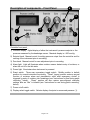
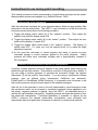
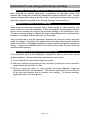
Model # HSPC-1
INSTRUCTION MANUAL
(V. 1.3, January 2004)
ALA Scientific Instruments Inc.
1100 Shames Drive
Westbury, NY 11590-1746
Tel. # 516 997-5780
Fax: # 516 997-0528
E-mail: [email protected]
www.alascience.com
Page 1 of 15
Table of Contents:
Page #
SAFETY INFORMATION AND GENERAL WARNINGS................................................ 3
ACKNOWLEDGEMENTS............................................................................................... 4
SHIPPING CONTENTS .................................................................................................. 5
DESCRIPTION OF COMPONENTS – FRONT PANEL.................................................. 6
DESCRIPTION OF COMPONENTS – REAR PANEL & HEADSTAGE ......................... 7
INTRODUCTION............................................................................................................. 8
INSTALLATION OF THE HSPC-1.................................................................................. 9
Positioning of components: ......................................................................................... 9
Connecting the tubing and electrical cords: ................................................................ 9
INSTRUCTIONS FOR USE DURING PATCH RECORDING ....................................... 11
Initial zeroing of the instrument ................................................................................. 11
Formation of cell-attached and whole-cell configuration. .......................................... 11
Execution of pressure clamp protocols in the patch-clamp configuration… .............. 12
Aspiration of moisture into the headstage. ................................................................ 12
Prolonging the longevity of the piezoelectric valve.................................................... 12
MAINTENANCE AND TROUBLESHOOTING.............................................................. 13
REFERENCES: ............................................................................................................ 14
WARRANTY ................................................................................................................. 15
Page 2 of 15
IMPORTANT NOTE: BEFORE BEGINNING ANY WORK WITH THE HSPC-1, PLEASE
READ THE ENTIRE MANUAL. FAILURE TO FOLLOW THE WARNINGS BELOW
MAY RESULT IN DAMAGE TO THE INSTRUMENT OR INJURY TO PERSONNEL.
Safety Information and General Warnings
1) The HSPC-1 requires a connection to mains power.
Incorrect usage or
carelessness may result in electrocution. Do not operate if the HSPC-1 is immersed
in liquids or if the electrical cables are damaged.
2) The DB9 cable that connects the headstage to the controller is custom-wired. Do
NOT substitute a standard cable with DB9 connectors.
3) Only trained scientific personnel, who are familiar with patch-clamp amplifiers,
should use this instrument.
4) If liquids spill on any part of the instrument, shut the instrument off and wipe up the
liquids before turning it on again.
5) The control box and headstage are not user serviceable. Unauthorized opening or
modification voids the warranty.
6) Do not position the HSPC-1 where someone might trip over the cords or tubing.
7) The HSPC-1 has an alarm system to prevent accidental suctioning of liquids into the
instrument. Circumventing this system voids the warranty.
8) The piezoelectric valve inside the headstage is highly sensitive. Follow the
suggestions in the “Prolonging the longevity of the piezoelectric valve (p.12)” section
to insure long life.
9) Do not apply voltages greater than ± 12 V to the command input.
10) The HSPC-1 should be plugged into a high quality surge protector to prevent
damage to sensitive components during electrical storms.
11) The HSPC-1 is not approved for clinical applications. ALA Scientific Instruments
discourages any such use and accepts no liability for such use.
Page 3 of 15
Acknowledgements
The HSPC-1 was developed by Drs. Stephen Besch, Thomas Suchyna and Frederick
Sachs at SUNY Buffalo. John Montalbano and Mohammad Ahmed, at ALA Scientific
Instruments, contributed to circuit design in the manufactured product. ALA Scientific
Instruments is also grateful for the contributions of Drs. Stephen Besch and Thomas
Suchyna in editing and writing the manual. This manual was written by Dr. Ian M.
Herzberg, with assistance from Stuart Havel for graphics and formatting.
Page 4 of 15
Shipping contents
The HSPC-1 shipment should include the following items:
a) Instruction manual (1)
b) Power cable (1)
c) Instrument controller (1)
d) Headstage (1)
e) Plastic bag containing various connectors (1)
f) Custom cable with 2 male DB9 connectors to connect headstage to controller (1)
g) Vacuum input and pressure input tubing
h) Thick-walled silicone tubing for connection of headstage output to electrode holder
(1)
Please open the box and the inspect contents immediately upon receipt. If any
components appear to be damaged or missing, please contact ALA Scientific
Instruments or your local distributor.
Page 5 of 15
Description of components – Front Panel
4
5
1
2
3
6
7
8
Controller front panel:
1) Pressure display. Digital display of either the instrument’s pressure setpoint or the
pressure measured by the headstage sensor. Maximal display is ± 200 mmHg.
2) Setpoint knob. Manual control for setting pressure output from the controller and for
zeroing of the instrument prior to recording.
3) Zero knob. Manual control for zero adjustment prior to recording.
4) Alarm light. Light will illuminate when moisture sensor detects entry of moisture, or
when the unit is in the idle state.
5) Power light. Illuminates when instrument is powered.
6) Reset switch. Three way momentary toggle switch. Middle position is default
position for normal instrument functioning. “Reset” (upper) position restores normal
function of moisture alarm and piezoelectric valve after emergency shutoff is
triggered by entry of moisture into headstage (see “Instructions for use during patch
recording,” below). “Reset” position will also restore preconfigured controller
settings after an “idle” is initiated (see “Instructions for use during patch recording”
below).
7) Power on/off switch.
8) Display select toggle switch. Selects display of setpoint or measured pressure (1).
Page 6 of 15
Description of components – Rear Panel & Headstage
9
10
11
12
Controller rear panel:
9) Power cord input. This instrument is preset to 110/120 V AC input (North American)
or 220/240 V AC (European) at the factory.
10) DB9 cable input. Input for custom cable that connects headstage and controller.
Substitution of standard cable with DB9 connector may damage instrument.
11) Monitor output. 20 mV/mmHg analog output from pressure sensor. Use to display
or record measured pressure. Standard BNC.
12) Command input. 20 mV/mmHg analog input. Use to control pressure from function
generator or acquisition software. Standard BNC.
R2
Headstage connections:
F1
R1
F1) Output connector (blue) for silicone tubing going to electrode holder.
R1) DB9 connector for cable from headstage to controller.
R2) Input source pressure connector (blue). Luer connector.
R3) Input source vacuum connector (yellow). Luer connector.
Page 7 of 15
R3
Introduction
The development of the voltage-clamp enabled stepping of excitable membrane
preparations to programmed voltages under closed-loop control. This enormously
advanced understanding of the function of voltage-gated channels (Bertil Hille, 1992).
Similarly, the “concentration-clamp” technique enabled rapid application of agonists to
ligand-sensitive excised patch preparations and advanced understanding of the function
of ligand-gated channels (Peter Jonas, 1995). Mechanosensitive ion channels are also
important physiologically (Hamill and Martinac, 2001), but the lack of instruments
capable of establishing a “pressure-clamp,” to enable stepping of mechanosensitive
preparations to programmed pressures under closed-loop control, has impeded
progress in understanding their function. ALA Scientific Instruments is proud to present
the HSPC-1, an instrument that enables any investigator familiar with the patch-clamp
technique to perform sophisticated pressure-clamp experiments on mechanosensitive
preparations in the excised patch or whole-cell patch clamp configuration.
Drs. Frederick Sachs, Thomas Suchyna and Stephen Besch built the earliest version of
the HSPC-1 at the University of Buffalo (Besch et al., 2002). The HSPC-1 is similar in
some respects to an earlier device by McBride and Hamill that employed piezoelectric
valves to partition pressure and vacuum sources under closed-loop control (McBride, Jr.
and Hamill, 1992). The current HSPC-1 features a miniaturized piezoelectric with
several innovations that improve response time, stability and valve longevity. These
innovations include supporting the piezo bimorph at both ends, minimizing valve dead
volume, placing the pressure sensor on the valve body and incorporating a piezo
element that does not require a static bias voltage.
A final innovation, the
moisture-sensitive optical sensor, protects the piezoelectric valve from contact with
moisture by triggering an automated application of positive outward pressure when
moisture is sensed (Besch et al., 2002).
Page 8 of 15
Installation of the HSPC-1
Positioning of components:
ALA strongly recommends the use of a Faraday cage to minimize radiative pickup
during patch-clamp recording and the use of an anti-vibration table to minimize damage
to seals during recording.
The headstage of the HSPC-1 should be positioned close enough to the electrode
holder of the patch pipette to permit connection to the pipette holder with the 10 cm
length of tubing provided. Use of exceptionally long (>10 cm) or distensible tubing (not
supplied by ALA Scientific Instruments) will delay and distort the pressure waveform
between the headstage and pipette holder. It is not necessary or desirable to bolt the
HSPC-1 headstage to the microscope or table prior to use.
All other electrical components, such as the HSPC-1 controller and electrically driven
pressure or vacuum sources, should be positioned outside of the Faraday cage.
Connecting the tubing and electrical cords:
Connect the output of the HSPC-1 headstage (F1) to the electrode holder of the
patch-clamp with the thick-walled tubing provided.
Please note that with the HSPC-1, it is possible to input pressures directly from a
function generator or acquisition software for gigaseal formation and membrane
rupturing (i.e., formation of the whole-cell configuration). Use of manual methods for
application of suction, e.g. by mouth or syringe, is unnecessary and inadvisable.
The headstage contains ports for input of pressure and vacuum. Connect the vacuum
port (R3) and pressure port (R2) to suitable vacuum and pressure sources with the
supplied tubing. The pressure source must be filtered to 5 µ or better to remove
particulates and oil.
ALA Scientific Instruments manufactures a device, the Pressure/Vacuum system for
HSPC-1 (catalog number ALA-PV-PUMP), that is designed to provide appropriate
pressure and vacuum to the respective inlet ports. Alternatively, other commercial
sources for these components are available. Should you choose to configure a system
from components from other vendors, please bear in mind the following:
1) For optimal valve performance, input pressure or vacuum should not exceed
± 500 mmHg. Higher pressures than this may not damage the valve, but may
prevent complete closing of the valve and thus hinder valve performance. The
recommended input pressure is ± 250 mmHg. At this pressure, consumption of air
is approximately 3 L/min.
2) Several types of pump may be suitable for generating pressure and vacuum.
Resonant piston pumps are recommended. They are quiet and reliable. The 60 Hz
component of the pressure output associated with these pumps can be eliminated
from the input by using filtering canisters. Appropriate canister size must be
determined empirically. A reasonable starting size is 250 ml.).
Page 9 of 15
Installation of the HSPC-1…
Connect the headstage to the controller using the custom cable with DB9 connectors.
(WARNING: do not substitute standard cables!) One end should attach to the
headstage socket (R1) and the other to the appropriate socket in the back of the
controller (10).
A BNC cable is used to connect the command input (12) to an appropriate analog
voltage source. The analog voltage waveform can be derived from any function
generator or from commercial electrophysiology experimental control/data acquisition
programs (e.g., npi electronic’s CellWorks, Axon Instruments pClamp, or HEKA
Electronik Pulse/PulseFit or PatchMaster) that generate an output command voltage.
However, if the desired experiment requires command waveforms to be generated
simultaneously to the voltage-clamp and pressure-clamp, the user should carefully
evaluate the specifications of any experimental control/data acquisition software to
make certain that the selected software has the required capabilities. Alternatively, a
custom signal generator that adheres to the required input limitations (maximum input
voltage ± 12 V) may also be used.
A BNC cable can be connected from the monitor output (11) to an oscilloscope or to an
A/D converter to observe or record the pressure measured at the headstage sensor.
Finally, the power cable should be plugged from the back of the instrument (9) into a
high quality surge protector.
At this point, all electrical and pressure/vacuum connections are complete and the
system can be powered on for initial zeroing and use.
Page 10 of 15
Instructions for use during patch recording
This manual presumes a basic understanding of patch-clamp technique by the reader.
Many excellent reviews are available (e.g. Reinhold Penner, 1995).
Initial zeroing of the instrument
After the instrument has been set up as described above, attach an appropriately filled
electrode to the electrode holder. The HSPC-1 may be turned on at this point and the
instrument zeroed according to the following procedure:
1) Toggle the display select switch (8) to the “setpoint” position.
setpoint knob until the display reads 00.0.
Then adjust the
2) Toggle the display select switch (8) to the “sensor” position. Then adjust the zero
knob until the display (1) reads 00.0.
3) Toggle the display select switch back to the “setpoint” position. The display (1)
should read 00.0. If it does not, turn the setpoint knob (2) to make the slight
adjustment required.
4) At this point the instrument is zeroed properly and ready to receive an input
command voltage to control pressure applied to the patch electrode. Output
pressure will follow input command voltages with a proportionality constant of
20.0 mmHg/mV.
Formation of cell-attached and whole-cell configuration.
A positive outward pressure should be applied to the patch pipette when lowering the
pipette through the bath medium. This prevents occlusion of the pipette tip by debris. If
you are using a function generator to generate the command voltage, the setpoint
adjustment (2) can be used for this purpose. If you are using a commercial software
program, such as pClamp (Axon Instruments), CellWorks (npi electronic),
Pulse/PulseFit or PatchMaster (HEKA Electronic), it is generally more convenient to set
this positive pressure using the control panel of the respective program.
After the tip of the electrode is close to the cell (determined by visual inspection under
the microscope and/or by an increase in measured resistance during application of a
test pulse), negative pressure is applied, using the HSPC-1 (as described above) to
achieve the cell-attached configuration. Negative pressure can again be applied to form
the whole-cell configuration. Controlled application of pressure or vacuum by the
HSPC-1 achieves the desired patch-clamp configuration more efficiently and
reproducibly than does application of pressure or vacuum by conventional methods.
Page 11 of 15
Instructions for use during patch-clamp recording...
Execution of pressure clamp protocols in the patch-clamp configuration…
After achieving the desired patch-clamp configuration as described above, both
pressure and voltage are controlled by independent negative feedback loops. You can
execute complex patch-clamp protocols exactly as you would voltage clamp protocols,
within the constraints described in the “General Warnings” section (above).
Aspiration of moisture into the headstage.
When using this instrument, aspiration with a broken pipette or other conditions may
cause moisture to enter the headstage. When this happens, the emergency moisture
sensor circuitry senses the moisture and prevents damage to the piezoelectric valve.
The input command voltage is disabled, the valve is immediately driven to apply positive
pressure to the pipette, and the alarm light (4) illuminates.
After a moisture alarm, stop the experiment, determine the source of moisture entry and
rectify the problem. Carefully dry the pipette holder and tubing connecting the electrode
holder to the HSPC-1 headstage (sometimes it may be simpler and faster to replace this
tubing). Toggling the reset/idle switch to the reset position clears the alarm state and
restores normal operation.
Prolonging the longevity of the piezoelectric valve.
The piezoelectric valve in the headstage is designed to last for years under normal
working conditions. Several simple steps will maximize its longevity:
1) Do not defeat the moisture alarm triggering circuitry.
2) Make sure that input air pressure is from a cylinder of purified air or from a house air
supply filtered with at least a 5 µ filter.
3) When not using the valve (i.e. when pipettes are being changed), toggle the
reset/idle switch (6) to the idle position. This causes a small volume of air to flow out
of the valve and prevents dust or moisture from entering. To resume recording,
toggle the switch to the reset position.
Page 12 of 15
Maintenance and Troubleshooting
With normal usage, no routine maintenance procedures are required other than
immediately wiping up liquids spilled on the instrument and cleaning or replacing the
contaminated components following moisture-triggered alarms. The HSPC-1 has no
user serviceable parts. If you have any problems with the HSPC-1, please contact ALA
Scientific Instruments (if bought within North America) or your local distributor.
Contact ALA Scientific Instruments by phone or email at the number or address below:
Email: [email protected]
Phone: (516) 997-5780
Fax:
(516) 997-0528
Page 13 of 15
References:
Bertil Hille (1992). Classical biophysics of the squid giant axon. In Ionic Channels of
Excitable Membranes, (Sunderland, MA: Sinauer Associates Inc.), pp. 23-58.
Besch,S.R., Suchyna,T., and Sachs,F. (2002). High-speed pressure clamp. Pflügers
Arch. 445, 161-166.
Hamill,O.P. and Martinac,B. (2001). Molecular basis of mechanotransduction in living
cells. Physiol Rev. 81, 685-740.
McBride,D.W., Jr. and Hamill,O.P. (1992). Pressure-clamp: a method for rapid step
perturbation of mechanosensitive channels. Pflügers Arch. 421, 606-612.
Peter Jonas (1995). Fast Application of Agonists to Isolated Membrane Patches. In
Single-Channel Recording, Bert Sakmann and Erwin Neher, eds. (New York: Plenum
Press), pp. 231-243.
Reinhold Penner (1995). Introduction to patch clamping. In Single-Channel Recording,
Bert Sakmann and Erwin Neher, eds. (New York: Plenum Press), pp. 3-30.
Page 14 of 15
Warranty
ALA Scientific Instruments agrees to warranty this product for a period of one year
from the date of delivery against any and all manufacturer’s defects in material and/or
workmanship (other than as noted below). Remedy will consist of repair or replacement
at ALA’s discretion. Please report any problems promptly so as not to jeopardize the
warranty coverage. ALA Scientific Instruments does not assume any liability based on
the use of this product, whether correct or incorrect, except as specified under law.
Warranty rights may vary from state to state.
ALA Scientific Instruments will not warranty any of the plastic connectors or tubing. Use
of the HSPC-1 in any way that contradicts the instructions of this manual may void the
warranty.
If the product does need repair, it must be returned to the factory freight prepaid (freight
sent collect will be refused) and in clean condition. If returned parts have been in
contact with any liquid substance, documentation of substances used must be provided
to ALA.
This product is intended for use in biophysical experiments with membrane or cellular
preparations only. THIS EQUIPMENT IS NEITHER INTENDED NOR APPROVED
FOR CLINICAL USE.
Page 15 of 15