1
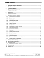
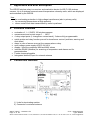
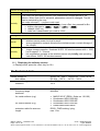
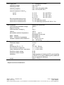
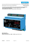
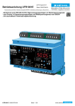
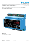
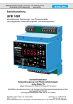
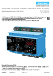
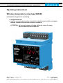
® MINIPAN digital panel meters, temperature- and mains controlling, special purpose instruments for customer requirements www.ziehl.com Operating instructions Wireless temperature relay type WR250 potential-free temperature monitoring Integrated antenna Input for external antenna when mounted in shielded area (metallic switchgear cabinet) or under difficult radio reception conditions ATTENTION: No external antenna included within the scope of supply. Please order extra when required. datum / name ) : 13.05.2011 Sc Page 1 of 20 Z. Nr.: 12200-0702-02 Type: WR250 ZIEHL industrie-elektronik GmbH + Co KG, Daimlerstr.13, D-74523 Schwäbisch Hall, Tel.: +49 791 504-0, Fax: -56, e-mail: [email protected] Table of Contents 1. Application and brief description ............................................................................ 3 2. Function overview ..................................................................................................... 3 3. Connection diagram ................................................................................................. 3 4. Display and control elements .................................................................................. 4 5. Important information ............................................................................................... 5 6. Installation ................................................................................................................. 6 7. Detailed description .................................................................................................. 6 8. Starting the wireless system .................................................................................... 7 8.1 General notes on operation ................................................................................... 7 8.2 Display mode ........................................................................................................ 7 8.3 Menu mode ........................................................................................................... 7 8.4 Parametrization mode ........................................................................................... 7 8.5 Operating flowchart ............................................................................................... 8 8.6 Startup overview.................................................................................................... 9 8.7 Configuration ......................................................................................................... 9 8.8 Registration of wireless sensors ............................................................................ 9 8.9 Alarm parametrization ......................................................................................... 10 8.10 Short-circuit monitoring ....................................................................................... 11 8.11 Relay test ............................................................................................................ 11 8.12 RS485 Modbus interface ..................................................................................... 12 8.13 Sensor Simulation ............................................................................................... 12 8.14 Code lock ............................................................................................................ 13 8.15 Notes on operation: ............................................................................................. 13 8.16 Device reaction time – measuring time tM ........................................................... 14 8.17 Possible values in the display ............................................................................. 14 9. Factory default settings .......................................................................................... 16 10. Servicing and maintenance .................................................................................... 17 11. Troubleshooting ...................................................................................................... 17 11.1 Displaying the software version ........................................................................... 18 12. Technical data ......................................................................................................... 18 13. Design V4 ................................................................................................................ 20 datum / name ) : 13.05.2011 Sc Page 2 of 20 Z. Nr.: 12200-0702-02 Type: WR250 ZIEHL industrie-elektronik GmbH + Co KG, Daimlerstr.13, D-74523 Schwäbisch Hall, Tel.: +49 791 504-0, Fax: -56, e-mail: [email protected] 1. Application and brief description The WR250 wireless relay is a receiver and evaluation device for WS Pt 100 wireless sensors. Up to 6 wireless sensors transmit temperature values by radio, which are displayed and evaluated by the WR250. Use: for overheating protection in high-voltage transformers (also in primary coils) for measuring temperatures at high potential where contact-free data transmission by radio is preferred 2. Function overview evaluation of 1 – 6 WS Pt 100 wireless sensors measurement and control range 0 … 180°C 4 relay output ports (1 changeover contact each), 3 alarms fully programmable switch points and relay function pre-set for transformer control (ventilator, warning and shut-down) alarm in case of sensor errors at the «sensor alarm» relay multi-voltage power supply AC/DC 24-240 V display / store the measured MIN and MAX values interface RS485 (Modbus) for scanning of temperature and alarms and for parametrization Feeder clamps pluggable Intergrated antenna, input for external antenna 3. Connection diagram 1) Links for terminating resistor 2) Connector for external antenna datum / name ) : 13.05.2011 Sc Page 3 of 20 Z. Nr.: 12200-0702-02 Type: WR250 ZIEHL industrie-elektronik GmbH + Co KG, Daimlerstr.13, D-74523 Schwäbisch Hall, Tel.: +49 791 504-0, Fax: -56, e-mail: [email protected] 4. Display and control elements 1 LEDs relay status K1, K2, K3 lit yellow = relay engaged sensor alarm (K4) lit red = relay disengaged 2 Digital display, 4 digits for temperature alarms (8Al1 8, 8Al2 8, 8Al3 8) error messages (8Err18 … 8Err98) menu and parameterization mode 3 Key «Up» (in Display mode, normal state) Press briefly: Change to menu mode (see operating instructions item 8.3) Confirmation for > 2 s: Display MAX values measured by the selected sensor. Additional pressing of the «Set» key for ≥ 2s will erase the stored MIN/MAX values. 4 Key «Set/Reset» (in Display mode, normal state) Press briefly: Display the next sensor (sensor LED lit) / display the highest temperature measured by all sensors (LEDs for all registered sensors lit) Confirmation for 10 s: Display the software version (z. B. 80-008) 5 Key «Down» (in Display mode, normal state) Press briefly: Change to Menu mode (see operating instructions item 8.3) Confirmation for > 2 s: Display the MIN value measured by the selected sensor. Additional pressing of the «Set» key for ≥ 2s will erase the stored MIN/MAX values. 6 Sensor LEDs Yellow LEDs on: indicate the wireless sensor currently displayed. If the LEDs for all registered sensors are lit, the warmest is being shown. Red LEDs on: indicate an error at the wireless sensor. The sensor can be selected using key «Set/Reset», and the display will show an Error Code (8Err 8). The following Error Codes are possible: 8Err18 sensor short-circuited at the WS Pt 100 wireless sensor 8Err28 sensor interruption at the WS Pt 100 wireless sensor 8Err38 no radio contact with the WS Pt 100 wireless sensor 8Err48 illumination of the WS Pt 100 wireless sensor too low 8Err58 energy level of the WS Pt 100 wireless sensor too low datum / name ) : 13.05.2011 Sc Page 4 of 20 Z. Nr.: 12200-0702-02 Type: WR250 ZIEHL industrie-elektronik GmbH + Co KG, Daimlerstr.13, D-74523 Schwäbisch Hall, Tel.: +49 791 504-0, Fax: -56, e-mail: [email protected] 5. Important information ! WARNUNG Dangerous electric voltage! May cause electric shock and burns. Before beginning work, disconnect system and device. Correct and safe operations of any device requires that it has been transported and stored appropriately, installed and commissioned correctly and is being operated according to the instructions. Only persons familiar with installation, start-up and operations and possessing qualifications appropriate for their work may perform work on the device. They must observe the contents of the operating instructions, the information printed on the device and the relevant safety regulations for construction and operation of electric installations. The devices are manufactured in accordance with DIN / EN and leave the production site in a condition of safety-related flawlessness. If in any case the information provided in the operating instructions should be insufficient, please contact us directly, or address your local representative. When using the device outside the area of applicability of the industrial norms referred to in the present operating instructions and valid in Europe, in their stead comply with the applicable regulations valid in the country of application. Caution! Do not connect or disconnect the device under power. Before connecting the device to the mains, make sure that the control voltage according to the type plate (on the side of the device) UC matches the voltage of the grid which the device is to be connected to! ! Caution! If the «operating current» function is programmed for all relays, a failure of control voltage or of the system may remain undetected. When using the device for control, it is the operator's responsibility to detect this error by regular controls. We recommend to program at least one relay in the system for standby current and to evaluate it accordingly. ! Caution! Multi-voltage power supply The device is equipped with a multi-voltage power supply suitable for DC and AC power supply. Before connecting the device to the mains, make sure that the permissible control voltage range according to the type plate (on the side of the device) UC matches the voltage of the grid which the device is to be connected to! datum / name ) : 13.05.2011 Sc Page 5 of 20 Z. Nr.: 12200-0702-02 Type: WR250 ZIEHL industrie-elektronik GmbH + Co KG, Daimlerstr.13, D-74523 Schwäbisch Hall, Tel.: +49 791 504-0, Fax: -56, e-mail: [email protected] 6. Installation The device can be fastened: Distributor installation or switching cabinet on 35 mm mounting rail according to EN 60715 Wall-mounting with M4 screws. (additional bar not included in delivery) Connect in accordance with connection diagram or type plate. Pay attention to the maximally permissible temperature when installing into a switching cabinet. Provide sufficient distance from other devices or heat sources. If cooling is hampered e. g. by close vicinity of devices with increased surface temperature or by obstruction of the cooling air flow, the permissible ambient temperature is reduced. 7. Detailed description The WR250 displays and evaluates the temperatures transmitted from the wireless sensors WS Pt 100. The hottest wireless sensor switches the relay. For the relays K1 (alarm 1), K2 (alarm 2) and K3 (alarm 3), the following can be selected individually: o alarm value o hysteresis o response and reset delay o operation current or standby current o cyclic relay test (e. g. K1 for ventilator) o alarm in case of error 3 (no radio contact with WS Pt 100) In case of an error at the WS Pt 100 wireless sensor, the relay will switch off the sensor alarm (K4), and the red LED is lit. In addition, the MIN and MAX temperature values of each WS Pt 100 wireless sensor are stored. The device can be polled remotely via a RS485 Modbus interface, and data can be queried. Under difficult radio reception conditions or unfavorable mounting positions (e.g. shielded switchgear-cabinet) an external antenna can be connected. For more informations concerning ranges and coverage see „APPLICATION NOTE AN001“ at www.enocean.de. datum / name ) : 13.05.2011 Sc Page 6 of 20 Z. Nr.: 12200-0702-02 Type: WR250 ZIEHL industrie-elektronik GmbH + Co KG, Daimlerstr.13, D-74523 Schwäbisch Hall, Tel.: +49 791 504-0, Fax: -56, e-mail: [email protected] 8. Starting the wireless system 8.1 General notes on operation The decimal point behind the last 7-element display shows the operating mode which the device is in. 8.2 Display mode Decimal point off (normal state for temperature display) Display current sensor temperature in °C (sensor LED lit) LED yellow K 1, K 2 and K 3 LED red sensor alarm LED Sensor WS Pt 100 function key «Set/Reset» function keys «Up» and «Down» Display the highest temperature measured by all attached sensors (LEDs for all active sensors lit) Display errors at the wireless sensor with error code (only when displaying individual sensors), e. g. 8Err18, 8Err28, … Display alarm messages (8Al1 8, 8al2 8 or 8al3 8) AN («on») = relay engaged AUS («off») = relay disengaged AN («on») = relay disengaged AUS («off») = relay engaged yellow = temperature of the selected wireless sensor is being displayed. If the LEDs for all registered sensors are lit, the hottest is being shown. red = error in selected wireless sensor Press briefly: Display the next sensor (sensor LED lit) and display the highest temperature measured by all sensors (LEDs for all registered sensors lit) Confirmation for 10 s: Display the software version Press briefly: Change to Menu mode Confirmation for ≥2 s: Display MIN and MAX values measured by the selected sensor. Additional pressing of the «Set» key for ≥ 2s will erase the stored values. 8.3 Menu mode Decimal point on Select the menu items for changing parameters function keys «Up» and «Down» function keys «Set/Reset» Press briefly: Select menu item; change to Display mode Press briefly: Change to Parametrization mode 8.4 Parametrization mode Decimal point flashing function key Press briefly/for a longer time: Change parameter value «Up» and «Down» (slow/fast) function keys Press briefly: Accept setting and selection of the next parameter, «Set/Reset» after the last parameter change to Menu mode Note: Press the «Set» key for 2 s to return to Display mode from Menu mode / Parametrization mode. The same thing happens if no key has been pressed for 30 s (Exception: 15 min in Simulation mode). datum / name ) : 13.05.2011 Sc Page 7 of 20 Z. Nr.: 12200-0702-02 Type: WR250 ZIEHL industrie-elektronik GmbH + Co KG, Daimlerstr.13, D-74523 Schwäbisch Hall, Tel.: +49 791 504-0, Fax: -56, e-mail: [email protected] 8.5 Operating flowchart Display mode normal state Menu mode Parametrization mode Sensor LEDs at the type plate indicate the corresponding input ports. «Up»/«Down» pressed simultaneously sets values to Zero. Code reset = 2 s «Set» upon mains power on (Pin = 504) Error messages: Err1 = short circuit in sensor Err2 = sensor interrupted Err3 = no radio contact Err4 = sensor illumination too low Err5 = sensor energy too low Err8 = internal error Err9 = parameter error datum / name ) : 13.05.2011 Sc Page 8 of 20 Z. Nr.: 12200-0702-02 Type: WR250 ZIEHL industrie-elektronik GmbH + Co KG, Daimlerstr.13, D-74523 Schwäbisch Hall, Tel.: +49 791 504-0, Fax: -56, e-mail: [email protected] 8.6 Startup overview required optional X X X X X X X Overview 8.7 configuration (basic settings of the device) 8.8 registration of wireless sensors WS Pt 100 8.9 alarm parametrization 8.10 relay test 8.11 sensor simulation 8.12 RS485 Modbus interface 8.13 code lock 8.7 Configuration The appropriate program must be selected in accordance with the settings of the wireless sensors (see operating instructions for WS Pt 100 wireless sensors). This is done once during commissioning. switch of control voltage at the WR250 keep «Set» key pressed and switch on control voltage again after 10 s, 8Pr 5 8 is shown in the display release «Set» key select program in accordance with the wireless sensors, using the «Up»/«Down» keys (program # see operating instructions for WS Pt 100 wireless sensor) press «Set» key device goes through reset and starts 8.8 Registration of wireless sensors Start in Display mode (return to Display mode by pressing «Set» key for ≥ 2s). After 30 s without input, the device will also return to Display mode. press «Down» key display 8S 1 .8 / 8off .8 (sensor 1 / off) flashes alternatingly press «Set» key press «Down» key («Up» key turns off the sensor input port) display 8on .8 (on) press «Set» key display 8adr .8 / 8lrn .8 (address / learn) flashes alternatingly within 30 s, briefly (approx. 1 s) link contacts 3 and 4 of the sensor plug-in socket at the WS Pt 100 wireless sensor (small wire jumper, or if the sensor plug is plugged in, briefly link the two contacts 3 and 4) registration OK: Display 8lrnd.8 (learned) will flash 4× registration error: Display 8Err .8 (error) will flash 4× display 8S 2 .8 / 8off .8 (sensor 2 / off) flashes alternatingly register sensors 2 to 6 (optional) after sensor 6, change to next menu item (parametrization of alarms) datum / name ) : 13.05.2011 Sc Page 9 of 20 Z. Nr.: 12200-0702-02 Type: WR250 ZIEHL industrie-elektronik GmbH + Co KG, Daimlerstr.13, D-74523 Schwäbisch Hall, Tel.: +49 791 504-0, Fax: -56, e-mail: [email protected] 8.9 Alarm parametrization The following parameters are important: alarm value 8AL 1.8 8AL 2.8 8AL 3.8 limit values for the alarms. alarm 1 for relay K1, alarm 2 for relay K2 and alarm 3 for relay K3. hysteresis 8H reset value calculated from alarm value + hysteresis e. g.: 90°C (limit value) + (-5)°C (hysteresis) = 85°C (reset value) alarm delay on alarm delay off 8dal .8 alarm will be suppressed for the selected time (seconds) 8dof .8 alarm will be switched off only after falling below limit (alarm value + hysteresis) and elapse of this time (seconds) .8 relay 8rel .8 SensorError 8SErr.8 standby current 8 r.8: In OK state (= alarm value not reached), the relay is engaged, it will be disengaged when reaching the alarm value. Advantage: errors and failures generally result in alarm Disadvantage: alarm also when control voltage is switched off. Unfavourable e. g. in transformers, in particular if WR250 control voltage is provided by the transformer to be controlled operating current 8 a.8: In OK state, the relay is disengaged, it will by engaged upon reaching the alarm value. No alarm in case of switched-off control voltage and failures. 8on .8 alarm if there is no radio contact with the WS Pt 100 wireless sensor (8Err38). 8off .8 no alarm in case of 8Err38 Selection: use the «Up» and «Down» keys to select menu item until … display 8AL 1.8 / 8 90.8 (alarm 1 / limit value) flashes alternatingly press «Set» key display 8 90.8 (current limit value, value may deviate) use the «Up» and «Down» keys to select the desired limit value press «Set» key display 8H .8 / 8 -5.8 (hysteresis / value) flashes alternatingly use the «Up» and «Down» keys to select the desired hysteresis press «Set» key display 8dal .8 / 8 0.8 (delay alarm / value) flashes alternatingly use the «Up» and «Down» keys to select the desired value press «Set» key display 8dof .8 / 8 0.8 (delay alarm off / value) flashes alternatingly use the «Up» and «Down» keys to select the desired value press «Set» key display 8rel .8 / 8 r.8 (relay / Parameter) flashes alternatingly use the «Up» and «Down» keys to select the desired value press «Set» key datum / name ) : 13.05.2011 Sc Page 10 of 20 Z. Nr.: 12200-0702-02 Type: WR250 ZIEHL industrie-elektronik GmbH + Co KG, Daimlerstr.13, D-74523 Schwäbisch Hall, Tel.: +49 791 504-0, Fax: -56, e-mail: [email protected] display 8SERR.8 / 8off .8 (sensor error / value) flashes alternatingly use the «Up» and «Down» keys to select the desired value press «Set» key display 8AL 2.8 / 8 100.8 (alarm 2 / limit value) flashes alternatingly parametrization of alarm 2 and alarm 3 after parametrization of alarm 3, change to next menu item (RS485 Modbus) 8.10 Short-circuit monitoring To avoid sensor-alarms at sensor-temperatures <0°C, short-circuit-monitoring can be deactivated. With short-circuit-monitoring de-activated, the WR250 will display -1°C at temperatures <0°C. Selection: use the «Up» and «Down» keys to select menu item until … display 8SESC.8 / 8on .8 (short-circuit monitoring / on) flashes alternatingly press «Set» key use the «Up» and «Down» keys to select the desired value display 8on .8 (on/with) / 8off .8 (off/without) press «Set» key (change to next menu item) 8.11 Relay test Here you can define that after a specified time 8don 8, e. g. 2 weeks (= 336 hours), a relay will go to alarm state for a time of 8dof 8, e. g. 10 s. This may be required to shortly start a ventilator of a pump to move them and prevent damage to the bearings by long downtimes. The following parameters are important: 8tst .8 Relay test relay test – Menu relay test alarm 1 (relay K1) 8AL 1.8 8AL 2.8 alarm # relay test alarm 2 (relay K2) 8AL 3.8 relay test alarm 3 (relay K3) time of test 8don .8 duration of test 8dof .8 shows after which time (in h) the relay test will be started or repeated, respectively shows how long (in s) the relay test will run How to adjust: Select menu item with «Up»/«Down» keys until … display shows 8tst .8 press «Set» key display 8AL .8 / 8E .8 (alarm / exit) flashes alternatingly Use the «Up» and «Down» keys to select the desired alarm # 8AL 1.8, 8AL 2.8, 8AL 3.8, or press 8E .8 (Exit) to leave the menu item press «Set» key display 8don .8 / 8off .8 (time of test / value) flashes alternatingly use the «Up» and «Down» keys to select the desired time for repetition of the relay test, 8off .8 – 8 1.8 – 8 999.8 h press «Set» key datum / name ) : 13.05.2011 Sc Page 11 of 20 Z. Nr.: 12200-0702-02 Type: WR250 ZIEHL industrie-elektronik GmbH + Co KG, Daimlerstr.13, D-74523 Schwäbisch Hall, Tel.: +49 791 504-0, Fax: -56, e-mail: [email protected] use the «Up» and «Down» keys to select the duration of the relay test, 8 1.8 – 8 999.8 s press «Set» key The elapsed test time 8don 8 is stored persistently in the device. 8.12 RS485 Modbus interface The following parameters are important: Modbus 8mbus.8 Modbus menu Address 8Adr .8 Address of device, selectable from range 1 to 247 baud rate parity 8baud.8 8pari.8 baud rate, 9600 or 19200 parity : 8even.8, 8odd .8, 8no .8 (even, odd, none) Selection: select menu item with «Up»/«Down» keys until … display 8Mbus.8 press «Set» key display 8Adr .8 / 8 1.8 (address / value) flashes alternatingly use the «Up» and «Down» keys to select the desired address press «Set» key display 8baud.8 / 8 9.6.8 (baud rate / value) flashes alternatingly use the «Up» and «Down» keys to select the desired baud rate press «Set» key display 8pari.8 / 8even.8 (parity / value) flashes alternatingly use the «Up» and «Down» keys to select the desired value press «Set» key leave menu item RS485 Modbus change to next menu item (Sensor Simulation) Further informations relating to Modbus configuration and programming can be found in Appendix 1 (available for download from www.ziehl.de). 8.13 Sensor Simulation Here you can simulate a temperature. All functions of the device will work as if this temperature were actually measured. If no key has been pressed for 15 minutes, the device automatically returns to Display mode. Select menu item with keys «Up»/«Down» until … display 8Si .8 press «Set» key use the «Up» and «Down» keys to select the desired temperature press «Set» key leave menu item Simulation change to next menu item (Code lock) datum / name ) : 13.05.2011 Sc Page 12 of 20 Z. Nr.: 12200-0702-02 Type: WR250 ZIEHL industrie-elektronik GmbH + Co KG, Daimlerstr.13, D-74523 Schwäbisch Hall, Tel.: +49 791 504-0, Fax: -56, e-mail: [email protected] 8.14 Code lock Here you can protect the entered parameters by activating code lock. The device will reject faulty input with 8Err 8 (flashes 3×). Select menu item with keys «Up»/«Down» until … display 8Cod .8 / 8off .8 (Code lock / off or on) flashes alternatingly press «Set» key display 8Pin .8 / 8 0.8 (pin / pin code) flashes alternatingly use the «Up» and «Down» keys to select the stored pin code (factory default setting is 8 504.8) press «Set» key use the «Up» and «Down» keys to select the desired code lock: o 8off .8 off, any parameter may be modified o 8EL .8 EasyLimit, only alarm values may be modified o 8on .8 on, no parameter may be modified press «Set» key display 8Pin .8 / 8 504.8 (pin / pin code) flashes alternatingly use the «Up» and «Down» keys to enter the desired new pin code (Caution: write down pin code) press «Set» key Code lock on, display 8on 8 flashes 3× Code lock EasyLimit, display 8EL 8 flashes 3× Code lock off, display 8off 8 flashes 3× leave menu item Code lock and change to Display mode (normal state). 8.15 Notes on operation: After completion of any program item, the program will continue with the next one. If the right decimal point of the 7-segment display is lit, you have left the Display mode and may select the individual menu items by pressing «Up»/«Down» (Menu mode). If the right decimal point flashes, you are in Parametrization mode and may change the settings by pressing «Up»/«Down». Pressing «Up»/«Down» for longer periods of time accelerates changes in the display. Pressing «Up»/«Down» simultaneously sets the selected values to zero. Reset (pressing «Set/Reset» for 2 s) will take you back to Display mode from any position in Parametrization mode or Menu mode (exception: Simulation), accepting the most recently entered value. datum / name ) : 13.05.2011 Sc Page 13 of 20 Z. Nr.: 12200-0702-02 Type: WR250 ZIEHL industrie-elektronik GmbH + Co KG, Daimlerstr.13, D-74523 Schwäbisch Hall, Tel.: +49 791 504-0, Fax: -56, e-mail: [email protected] 8.16 Device reaction time – measuring time tM The reaction time of the device depends on the measuring and transmission times of the wireless sensors (see operating instructions WS Pt 100 wireless sensor). The wireless sensors measure the temperature every 1 s, 10 s or 100 s and transmit it to the WR250 after every single, after every 10th or after every 100th measurement. Consequently, there may be delays in sending and evaluating temperature changes. Temperature changes > 4 °C will be sent immediately after measurement. The delay times 8dal .8 and 8dof .8 may be increased by the duration of the transmission intervals (± 20%). 8.17 Possible values in the display In Display mode (normal state) alarm 1, alarm 2, alarm 3 active (relay function dependent on 8al1 8/8al2 8/8al3 8 programming for standby or operating current) 8Err18 sensor short-circuited at the WS Pt 100 wireless sensor 8Err28 sensor interruption at the WS Pt 100 wireless sensor 8Err38 no radio contact with the WS Pt 100 wireless sensor 8Err48 illumination of the WS Pt 100 wireless sensor too low 8Err58 energy level of the WS Pt 100 wireless sensor too low 8Err88 WR250 internal error 8Err98 parameter error (illogic configuration of the WR250) sensors, Menu mode / Parametrization mode 8S 1 8 … 8S 2 8 sensors 1 to 6 8on 8 / 8off 8 sensors on / off 8Adr 8 / 8Lrn 8 flashes alternatingly, ready for registration of a new sensor 8Lrnd8 new sensor registered successfully (learned) alarm values, Menu mode / Parametrization mode 8al 18/8al 28/8al 38 alarm values 8H 8 hysteresis 8dal 8 delay until alarm 8dof 8 delay until alarm reset 8rel 8 relay function 8 r8 / 8 a8 relay function – standby current, operating current Short-circuit monitoring, Menu mode / Parametrization mode 8SESC8 Short-circuit monitoring 8off 8 / 8on 8 datum / name ) : 13.05.2011 Sc Page 14 of 20 off (without) / on (with) Short-circuit monitoring Z. Nr.: 12200-0702-02 Type: WR250 ZIEHL industrie-elektronik GmbH + Co KG, Daimlerstr.13, D-74523 Schwäbisch Hall, Tel.: +49 791 504-0, Fax: -56, e-mail: [email protected] relay test, Menu mode / Parametrization mode 8tst 8 relay test 8AL 8 / 8E 8 8al 18/8al 28/8al 38 alarm / exit relay test on alarm 1 (K1) / alarm 2 (K2) / alarm 3 (K3) shows after which time (in h) the relay test will be started or repeated, respectively shows how long (in s) the relay test has been running 8don 8 8dof 8 RS485 interface Modbus, Menu mode / Parametrization mode 8Mbus8 Modbus (RS485 interface) 8adr 8 Modbus – device address 8baud8 Modbus – baud rate 8 9.68 / 8 19.28 8pari8 8even8 / 8odd 8 / 8no 8 Modbus – baud rate, 9600 or 19200 Modbus – parity Modbus – parity bit – even / odd / none Simulation, Menu mode / Parametrization mode 8Si 8 Simulation Code lock, Menu mode / Parametrization mode 8Cod 8 Code lock 8Pin 8 pin code 8on 8 / 8el 8 / 8off 8 datum / name ) : 13.05.2011 Sc Page 15 of 20 Code lock on / EasyLimit / off Z. Nr.: 12200-0702-02 Type: WR250 ZIEHL industrie-elektronik GmbH + Co KG, Daimlerstr.13, D-74523 Schwäbisch Hall, Tel.: +49 791 504-0, Fax: -56, e-mail: [email protected] 9. Factory default settings When switching the program (operating instructions item «Configuration»), all parameters are reset to their factory default settings. Menu Factory default My data Parameter mode settings 8S 1 8 8off 8 8S 2 8 8off 8 sensor 8S 3 8 8off 8 1 .. 6 8S 4 8 8off 8 8S 5 8 8off 8 8S 6 8 8off 8 limit 8AL 18 8 908 °C hysteresis 8H 8 8 -108 °C alarm 1 delay – alarm 8dal 8 8 08 s delay – alarm off 8dof 8 8 9998 s relay K1 relay function 8rel 8 8 a8 alarm sensor error 3 8SErr8 8on 8 limit 8AL 28 8 1308 °C hysteresis 8H 8 8 -58 °C alarm 2 delay – alarm 8dal 8 8 08 s delay – alarm off 8dof 8 8 08 s relay K2 relay function 8rel 8 8 r8 alarm sensor error3 8SErr8 8off 8 limit 8AL 38 8 1508 °C hysteresis 8H 8 8 -58 °C alarm 3 delay – alarm 8dal 8 8 08 s delay – alarm off 8dof 8 8 08 s relay K3 relay function 8rel 8 8 a8 alarm sensor error3 8SErr8 8off 8 Short-circuit monitoring SESC 8SESC8 8on 8 8don 8 8off 8 Time of test 8AL 18 8dof 8 8 18 duration of test relay 8don 8 8off 8 Time of test test 8AL 28 8dof 8 8 18 duration of test tst 8don 8 8off 8 Time of test 8AL 38 8dof 8 8 18 duration of test 8adr 8 8 18 8baud8 8 9.68 Modbus 8Pari8 8even8 8off 8 8on 8 / 8el 8 / 8off 8 Cod 8Pin 8 8 5048 datum / name ) : 13.05.2011 Sc Page 16 of 20 Z. Nr.: 12200-0702-02 Type: WR250 ZIEHL industrie-elektronik GmbH + Co KG, Daimlerstr.13, D-74523 Schwäbisch Hall, Tel.: +49 791 504-0, Fax: -56, e-mail: [email protected] 10. Servicing and maintenance ZIEHL industrie-elektronik GmbH + Co KG Daimlerstr.13 D-74523 Schwäbisch Hall Germany Phone: +49 791 504-0 Fax: +49 791 504-56 Email: [email protected] Homepage: http://www.ziehl.de 11. Troubleshooting 8Err18 or 8Err28 shown in the display cause sensor short-circuited or sensor interrupted at the WS Pt 100 wireless sensor please check temperature sensor at the WS Pt 100 wireless sensor for being remedy electrically in order and correctly connected. (see operating instructions: WS Pt 100 wireless sensor) 8Err38 shown in the display no radio contact with the WS Pt 100 wireless sensor distance from WS Pt 100 wireless sensor too great cause storage capacitor in the WS Pt 100 wireless sensor exhaustively discharged reduce distance between devices remedy charge storage capacitor, illuminate WS Pt 100 wireless sensor with > 1000 lux for approx. 2 – 3 hours 8Err48 shown in the display cause illumination of the WS Pt 100 wireless sensor too low or failed remedy provide illumination or increase light intensity, respectively 8Err58 shown in the display cause energy level of the WS Pt 100 wireless sensor too low charge storage capacitor, illuminate WS Pt 100 wireless sensor with > 1000 lux remedy for approx. 2 – 3 hours 8Err88 shown in the display cause WR250 internal error remedy send the device in for examination 8Err98 shown in the display cause Parameter error (implausible configuration of WR250) remedy check alarm parametrization datum / name ) : 13.05.2011 Sc Page 17 of 20 Z. Nr.: 12200-0702-02 Type: WR250 ZIEHL industrie-elektronik GmbH + Co KG, Daimlerstr.13, D-74523 Schwäbisch Hall, Tel.: +49 791 504-0, Fax: -56, e-mail: [email protected] Device refuses programming cause Code lock remedy The code lock provides protection from unauthorized manipulations of the device. When code lock is activated, parameters cannot be changed. The pin can be selected by the user. pin code unknown? → perform code reset: Upon activation of the control voltage, keep «Set» key pressed for 2 s display changes to 888888 – 8Cod 8 – 8off 8 – 888888 release «Set» key code lock is deactivated, pin code is «504» No registration of a WS Pt 100 wireless sensor with the WR250 possible distance between wireless sensor and WR250 too great wireless sensor power too low for work cause wrong registration contacts linked at the wireless sensor or static linkage of the contact reduce distance between the devices charge storage capacitor, illuminate WS Pt 100 wireless sensor with > 1000 remedy lux for approx. 2 – 3 hours link registration contacts at the wireless sensor only briefly (see operating instructions: WS Pt 100 wireless sensor) 11.1 Displaying the software version In Display mode, press the «Set» key for 10 s 12. Technical data control voltage UC limit values measurement range tolerance AC/DC 24 – 240 V 0/50/60 Hz <3 W < 6 VA DC 20.4 – 297 V AC 20 – 264 V 0 … 180°C ±4K input for external antenna frequency range antennas: for metal surfaces (e.g.) FME plug 868 MHz for other surfaces (e.g.) extension-cable for antenna length datum / name ) : 13.05.2011 Sc Page 18 of 20 MAR-C3G-2F (ZIEHL, Order-no. 101100) Hirschmann MCA 1890 MH Hirschmann MCA 1890 MP Hirschmann MCA 1890 MP HAMA MiniPlanar 38499 RG58 - FME bushing / plug max. 15m Z. Nr.: 12200-0702-02 Type: WR250 ZIEHL industrie-elektronik GmbH + Co KG, Daimlerstr.13, D-74523 Schwäbisch Hall, Tel.: +49 791 504-0, Fax: -56, e-mail: [email protected] relay output port switching voltage switching current switching capacity Nominal operation current IE: AC15 DC13 Recommended backup fuse service life of contacts mech. service life of contacts electr. Test conditions rated impulse withstand voltage degree of soiling rated insulation voltage UI Uptime permissible ambient temperature EMC – stability EMC – interference emissions vibration resistance EN 60068-2-6 Casing installation depth width dimensions (B × H × T) line connector, single wire finely stranded with wire end ferrule Protection class, casing Protection class, clamps fastening weight 4 × 1 changeover contact max. AC 415 V max. 5 A max. 1250 VA (ohmic load) max. 120 W at DC 24 V Ie = 3 A Ue = AC 250 V Ie = 2 A Ue = DC 24 V Ie = 0,2 A Ue = DC 125 V Ie = 0,1 A Ue = DC 250 V T 3.15 A (gL) 3 x 10⁷ switching cycles 1 x 10⁵ switching cycles at AC 250 V / 6 A EN 50178 / EN 60 947 4000 V 3 300 V 100 % -20 °C … +60 °C EN 60068-2-2 dry heat EN 61000-6-2 EN 61000-6-3 2 … 25 Hz ±1,6 mm 25 … 150 Hz 5 g V4 design, distributor installation 55 mm 4 TE 70 × 90 × 58 mm 1 × 1.5 mm² each 1 × 1.0 mm² each IP 30 IP 20 snap mounting on bearing rail 35 mm according to EN 60 715 or screw fastening M 4 (additional bar not included in delivery) approx. 190 g Subject to technical modifications datum / name ) : 13.05.2011 Sc Page 19 of 20 Z. Nr.: 12200-0702-02 Type: WR250 ZIEHL industrie-elektronik GmbH + Co KG, Daimlerstr.13, D-74523 Schwäbisch Hall, Tel.: +49 791 504-0, Fax: -56, e-mail: [email protected] 13. Design V4 Dimensions in mm 58 70 48 Option 98 116 (90) 5 45 61,8 16,5 3 4 7 1 1 2 3 4 5 6 7 6 2 3 Oberteil / cover Unterteil / base Riegel / bar for snap mounting Plombenlasche / latch for sealing Frontplatteneinsatz / front panel Kennzeichen für unten / position downward Riegel bei Wandbefestigung mit Schrauben. Riegelbohrung Ø 4,2 mm / for fixing to wall with screws, Ø 4,2 mm Sie finden diese und weitere Betriebsanleitungen, soweit verfügbar auch in englisch, auf unserer Homepage www.ziehl.de. You find this and other operating-manuals on our homepage www.ziehl.de, as far as available also in English. datum / name ) : 13.05.2011 Sc Page 20 of 20 Z. Nr.: 12200-0702-02 Type: WR250 ZIEHL industrie-elektronik GmbH + Co KG, Daimlerstr.13, D-74523 Schwäbisch Hall, Tel.: +49 791 504-0, Fax: -56, e-mail: [email protected]