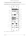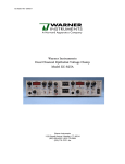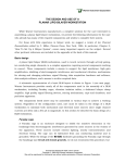
1
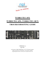
TURBO TEC-03X TURBO TEC-05X, TURBO TEC-10CX TROUBLESHOOTING GUIDE VERSION 1.6 npi 2013 npi electronic GmbH, Bauhofring 16, D-71732 Tamm, Germany Phone +49 (0)7141-9730230; Fax: +49 (0)7141-9730240 [email protected]; http://www.npielectronic.com TURBO TEC Troubleshooting Guide _________________________________________________________________________________________________________________ 1. Intention of this Guide This manual is written to enable the user to set up and test the basic functions of a Turbo TEC amplifier from npi. Furthermore, some hints are given for the case that something goes wrong and it should help to find errors. Front panel, controls and connectors refer to the TEC-03X amplifier, but the following instructions are also valid for TEC-05X and TEC-10CX amplifiers. With TEC-05X and TEC10CX amplifiers please follow these tests analogue to TEC-03X. TEC-05X and TEC-10CX have different front panel elements. In the test procedures these elements are mentioned separately. ___________________________________________________________________________ version 1.6 page 2 TURBO TEC Troubleshooting Guide _________________________________________________________________________________________________________________ 2. Testing basic functions of TURBO TEC-03X amplifier In the following instructions are given to test the basic functions of TEC-03X amplifiers and to exclude “simple” errors (see also TURBO TEC-03X user manual). Figure 1: TURBO TEC-03X front panel view ___________________________________________________________________________ version 1.6 page 3 TURBO TEC Troubleshooting Guide _________________________________________________________________________________________________________________ 2.1. Electrical connections All numbers are related to Figure 1. Turn POWER off. Connect the TEC-03X to mains using the mains cord. Connect the potential headstage cable to the POTENTIAL HEADSTAGE connector (#20) at the TEC-03X. Connect the current headstage cable to the CURRENT HEADSTAGE connector (#22) at the TEC-03X. Connect a cell model (see chapter 2.3). Connect a digital/analog timing unit (e.g. a computer with multifunction I/O board) or a stimulation device (e.g. a pulse generator) to COMMAND INPUT (#31). TEC-10CX: Connect a digital/analog timing unit (e.g. a computer with multifunction I/O board) or a stimulation device (e.g. a pulse generator) to CURRENT STIMULUS INPUT 1V/µA for Current Clamp (CC), or to VOLTAGE COMMAND INPUT ÷10 for Voltage Clamp (VC). Connect a storage oscilloscope or a data recording device (e.g. a computer with data acquisition card) to the POTENTIAL OUTPUT PEL and to the CURRENT OUTPUT triggered from the stimulation device. We recommend always to use an oscilloscope in addition to the computer system. Set the desired gain at the CURRENT OUTPUT SENSITIVITY switch (#15) and set the CURRENT FILTER (#14) to 20k. TEC-10CX: Connect a storage oscilloscope or a data recording device (e.g. a computer with data acquisition card) to the POTENTIAL OUTPUT PEL x10, and to the CURRENT OUTPUT triggered from the stimulation device. Figure 2: basic electrical connections Before using the TEC-03X always make the basic settings (see below) to avoid oscillations. ___________________________________________________________________________ version 1.6 page 4 TURBO TEC Troubleshooting Guide _________________________________________________________________________________________________________________ 2.2. Basic settings It is assumed that the BIAS current has been tuned to zero (see respective TEC manual). Turn all controls to low values (less than 1) and each symmetrical offset adjustment in the range of 5 (zero position). For users of the four-range headstage Set the range switch to x1. Disable the HOLD unit by setting the + / 0 / - switch (#25) to 0. Set the MODE OF OPERATION (#28) to CC. Set the display to POTENTIAL ELECTRODE using switch #7. 2.3. Connecting the cell model Connect the PEL BNC jack of the cell model to the BNC connector at the potential headstage. Connect the SUBCLICK connector REF. to the REF. connector at the potential headstage. Connect the SUBCLICK connector CEL to the plug at the current headstage. Switch the CELL membrane switch at the cell model to 100K. Set the GND switch at the cell model to ON. Turn POWER switch of the amplifier on. Now you can adjust the amplifier and apply test pulses to the cell model (see below). Connection to the BNC- and SUBCLICK connector respectively gives access to the cell via a potential and current electrode with 1 M resistance. In the upper position the RM switch simulates a cell membrane with a resistance of 10 k. In the lower position a cell membrane with 100 k is simulated. The membrane capacity is always 100 nF. 2.4. Testing Operation Modes Important: The TEC-03X should be used only in warmed-up condition, i.e. 20 to 30 minutes after turning power on. General Considerations The key to accurate and fast recording is a properly built setup. Make sure that the internal system ground is connected to only one point on the measuring ground and originates from the potential headstage. Multiple grounding should be avoided; all ground points should originate from a central point. The electrode used for grounding the bath should have a low resistance so that it can pass large currents. Use electrodes with resistances as low as possible. Keep cables short. Use differential potential recording and a driven shield configuration. ___________________________________________________________________________ version 1.6 page 5 TURBO TEC Troubleshooting Guide _________________________________________________________________________________________________________________ Check regularly whether cables and connections are broken (very important). Make sure that chloriding of silver wires for the electrodes is proper and that there are no unwanted earth bridges e.g. salt bridges originating from experimental solutions. Current Clamp In the current clamp mode the cell's response to current injections is measured. Current injection is performed by means of a current source connected to the current injecting microelectrode. Important: In case of trouble first check whether all connections are built correctly and make sure that the oscillation shut off unit is not active. Connect a cell model and turn power on. Watch the OSCILLATION SHUTOFF unit. The LED (#3) must light green. If not: disable the unit with switch #2. With the MODE OF OPERATION switch (#28) set the amplifier to CC mode. LED (#27) should light up. If not already done tune the BIAS current to zero (see chapter 8.1, user manual for TEC-03X or page 21 for TEC-10CX). Compensate the offsets of the current and voltage electrode using offset controls (#16 and #18; see chapter 8.2, user manual for TEC-03X or page 8 for TEC-10CX). Displays should read values around zero. If not check: HOLD disabled? Electrode resistance test disabled? BIAS current adjusted? Capacity compensation set to 0? No signal at COMMAND INPUT? (if you are not sure, disconnect) Offset cannot be compensated headstage may be damaged (contact npi). If all works correctly: Test the resistance of the current and the voltage electrode (see chapter 8.3, user manual). Display should read 1 M (5 %). If not check: npi cell model connected? (should mean: are really 1 M electrodes simulated?) Range switch at current headstage in position 1? This is a must for correct display of the resistance. Cell model OK (see also chapter 3 of this guide) If this is the case the headstage may be damaged contact npi. If all works correctly: Set Rm at the cell model to 10k. ___________________________________________________________________________ version 1.6 page 6 TURBO TEC Troubleshooting Guide _________________________________________________________________________________________________________________ Set the holding current to –1 µA using the HOLD potentiometer (#12) (reading: 1.00 µA) and the HOLD current polarity switch (#25) (set to -). Make sure that the potential switch (#7) is set to POTENTIAL electrode and the ELECTRODE RESISTANCE test is not active. The POTENTIAL display should read –10 mV (according to Ohm's law). The voltage at PEL (#33) should be -100 mV. If not check: POTENTIAL switch (#7) set to POTENTIAL ELECTRODE? HOLD current polarity switch (#25) set to -? ELECTRODE RESISTANCE disabled? Remember: The voltage at PEL (x10) is the membrane potential multiplied by 10! Disable the holding current and apply a test pulse of 2 µA to the cell model by giving a voltage step of 2 V to COMMAND INPUT (#31). The length of the test pulse should be at least 50 ms. You should see a potential step of 200 mV amplitude at PEL (#33). Due to the membrane capacity the step is smoothed. If not: amplifier might be damaged contact npi. Note: If you expect the POTENTIAL display to show the value of the potential step (in this case +20 mV amplitude) remember that the display is rather sluggish and may not display the right value (depending on the length of the step). The same applies to the CURRENT display. Voltage Clamp In voltage clamp mode, the membrane potential is forced by a controller to maintain a certain value or to follow an external command. That allows measurement of ion fluxes across the cell membrane. This is the most complex mode of operation with the TEC-03X or TEC10CX. Special precautions must be taken while tuning the control circuit in order avoid stability problems. TEC-03X Make sure that the amplifier works correctly with the cell model in CC mode (see above). Set the holding potential to –50 mV using the HOLD potentiometer (#12) (reading: 050 mV) and the HOLD potential polarity switch (#25) (set to -). Remember: The HOLDING potentiometer sets the holding current in CC mode and the holding potential in VC mode. Set the control mode switch (#6) to NORMAL, GAIN ONLY. Set the CAPACITY COMPENSATION to zero and the GAIN (#5) to 1. Enable the OSCILLATION SHUTOFF unit with a moderate THRESHOLD (DISABLED / RESET switch (#2) in middle position, OSCILLATION SHUTOFF LED green, TRESHOLD potentiometer set to a low value, but not to the most left position) ___________________________________________________________________________ version 1.6 page 7 TURBO TEC Troubleshooting Guide _________________________________________________________________________________________________________________ For troubleshooting with the cell model you should disable the OSCILLATION SHUTOFF unit Set the amplifier with the MODE OF OPERATION switch (#28) to VC mode. The upper display should show the holding potential of –50 mV and the lower display the holding current of –5 µA (according to Ohm's law). It is very likely that the display shows a holding potential of slightly less than –50 mV because the controller is in NORMAL, GAIN ONLY mode (see also Appendix in the User Manual) and the GAIN is low. Increasing GAIN and setting the controller to SLOW (Integrator) mode will enhance the control loop and therefore increase accuracy. TEC-10CX Make sure that the amplifier works correctly with the cell model in CC mode (see above). Set the holding potential to –50 mV using the HOLDING POTENTIAL potentiometer (reading: 050 mV) and the HOLDING POTENTIAL polarity switch (set to -). Set the VC OUTPUT LIMITER to 100%. Set the COMMAND FILTER TIME CONSTANT to 10 µs. Set the SERIES RESISTANCE COMPENSATION to OFF. Set the INTEGRATOR TIME CONSTANT to OFF. Set the CAPACITY COMPENSATION to zero and the GAIN to 1. Enable the OSCILLATION SHUTOFF unit with a moderate THRESHOLD (DISABLED / RESET switch in middle position, OSCILLATION SHUTOFF LED green, THRESHOLD potentiometer set to a low value, but not to the most left position) For troubleshooting with the cell model you should disable the OSCILLATION SHUTOFF unit Set the amplifier with the MODE OF OPERATION button to VC mode. The upper display should show the holding potential of –50 mV and the lower display the holding current of –5 µA (according to Ohm's law). It is very likely that the display shows a holding potential of slightly less than –50 mV because the controller is in normal, gain only mode without INTEGRATOR (see also Appendix in the User Manual) and the GAIN is low. Increasing GAIN and setting INTEGRATOR TIME CONSTANT (Integrator mode) will enhance the control loop and therefore increase accuracy. TEC-03X and TEC-10CX If the system oscillates as soon as you switch to VC mode switch back to CC mode and check the settings. GAIN too high? CAPACITY COMPENSATION not zero? TRESHOLD potentiometer of the OSCILLATION SHUTOFF unit at the most left position? TEC-03X Control mode switch not to NORMAL, GAIN ONLY or SLOW (Integrator)? ___________________________________________________________________________ version 1.6 page 8 TURBO TEC Troubleshooting Guide _________________________________________________________________________________________________________________ TEC-10CX INTEGRATOR TIME CONSTANT on and set to a too high value? SERIES RESISTANCE COMPENSATION on and set to a too high value? If all works correctly: Apply a test pulse of 20 mV to the cell model by giving a voltage step of 0.2 V to COMMAND INPUT (#31, TEC-03X) or VOLTAGE COMMAND INPUT ÷10 (TEC-10CX). The length of the test pulse should be at least 30 ms. You should see a potential step of 200 mV amplitude at PEL (#33, TEC-03X) or PEL x10 (TEC-10CX). If not Contact npi Note: If you expect the POTENTIAL display to show the value of the potential step (in this case 20 mV amplitude i.e. –30 mV) remember that the display is rather sluggish and may not display the right value (depending on the length of the step). The same is true for the CURRENT display. 3. Testing the cell model All you need for this test is a simple ohmmeter. Please run these test with the switch for grounding the current electrode set to ON. Test 1: Measure the resistance between the two inputs, i.e. the inner contacts of PEL and CEL at the cell model. The resistance must be 2 M. Test 2: Measure the resistance between PEL (inner contact) and GND-plug. Switch the membrane resistance to 10k. The resistance must be 1.011 M. Switch the membrane resistance to 100k. The resistance must be 1.101 M. Test 3: Measure the resistance between CEL (inner contact) and GND-plug. Switch the membrane resistance to 10k. The resistance must be 1.011 M. Switch the membrane resistance to 100k. The resistance must be 1.101 M. Test 4: Measure the resistance between REF (inner contact) and GND-plug. The resistance must be 2 k. Test 5: Verify that there is a connection between the shields (outer part of the plugs) of CEL and REF to GND, respectively. Test 6: Verify that there is no short circuit between GND and the shield of the potential electrode, i.e. the ohmmeter must display infinite. If you measure these values the cell model is OK! ___________________________________________________________________________ version 1.6 page 9