1
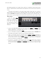
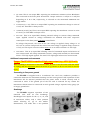
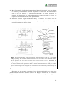
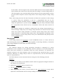
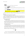
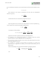
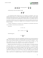
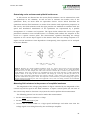
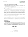
EC-825A, Rev 120924.1 Warner Instruments Dual Channel Epithelial Voltage Clamp Model EC-825A Warner Instruments 1125 Dixwell Avenue, Hamden, CT 06514 (800) 599-4203 / (203) 776-0664 (203) 776-1278 - fax EC-825A, Rev 120924.1 Table of Contents NOMENCLATURE .................................................................................................................................... 5 CONTROL DESCRIPTION...................................................................................................................... 6 Channel 1 and 2 control blocks ............................................................................................................. 6 Offset .................................................................................................................................................... 6 Clipping ................................................................................................................................................ 6 Meter .................................................................................................................................................... 7 Command ............................................................................................................................................. 7 Mode ..................................................................................................................................................... 7 Fluid Resistance ................................................................................................................................... 8 Clamp Response ................................................................................................................................... 8 Timer control blocks .............................................................................................................................. 9 Timer A ................................................................................................................................................. 9 Timer B ................................................................................................................................................. 9 Rear panel description ........................................................................................................................... 9 Grounds, line power connector, and fuse............................................................................................. 9 Timer section ...................................................................................................................................... 10 I/O interface ....................................................................................................................................... 11 Channel BNC’s ................................................................................................................................... 11 Additional components and comments ............................................................................................... 12 Connecting to line power ground ....................................................................................................... 12 Headstage ........................................................................................................................................... 12 Connecting the headstages ................................................................................................................. 13 SETUP AND INITIAL TEST .................................................................................................................. 14 Equipment ............................................................................................................................................. 14 Chambers ........................................................................................................................................... 14 Electrodes ........................................................................................................................................... 15 Electronics.......................................................................................................................................... 17 Quick test............................................................................................................................................... 19 Initial control settings ........................................................................................................................ 19 Monitoring model membrane voltage ................................................................................................ 19 Checking zero voltage clamp ............................................................................................................. 19 Check voltage clamp command .......................................................................................................... 19 Checking clamp current on panel meter ............................................................................................ 20 Fluid Resistance compensation .......................................................................................................... 20 EC-825A, Rev 120924.1 OPERATION ............................................................................................................................................ 21 Connecting the EC-825A ..................................................................................................................... 21 From epithelium to headstage ............................................................................................................ 21 From the current/voltage clamp to external monitors ....................................................................... 21 Checking for asymmetries in the voltage electrodes ......................................................................... 21 Recording modes .................................................................................................................................. 22 Warning lights ...................................................................................................................................... 23 Fluid resistance ..................................................................................................................................... 23 Analyzing the electrical properties of an epithelium ......................................................................... 24 Transepithelial voltage ....................................................................................................................... 24 Transepithelial resistance .................................................................................................................. 24 Short circuit current ........................................................................................................................... 25 Equivalent circuit analysis ................................................................................................................. 25 Determining series resistance and epithelial surface area ................................................................ 29 Determining series resistance and epithelial surface area ................................................................ 30 Measuring fluid resistance in the presence of an epithlial membrane ............................................... 30 Measuring epithelial surface area ..................................................................................................... 31 Further considerations ....................................................................................................................... 31 APPENDIX ................................................................................................................................................ 33 References and recommended reading ............................................................................................... 33 Chloriding silver wires ......................................................................................................................... 33 Adjusting the fluid resistance measurement range ........................................................................... 34 Connecting the EC-825A to Acquire & Analyze ............................................................................... 34 Hardware connections ....................................................................................................................... 34 Software configuration ....................................................................................................................... 35 Specifications......................................................................................................................................... 37 EC-825A, Rev 120924.1 The EC-825A Epithelial Voltage Clamp from Warner Instruments is a two channel device providing accurate measurement of transepithelial voltage, short circuit current and membrane resistance. Important features include fluid resistance compensation, membrane resistance readout, high voltage compliance and small, watertight headstages. Operating modes include voltage clamp, current clamp, voltmeter and resistance. Unique Features Include Membrane Resistance Measurement: Accurate resistance measurements are made with the membrane mounted in the chamber. A low frequency bipolar signal is used to avoid polarization of the membrane (ideal for monolayers). Resistances up to 200 k are displayed on the meter. Clamp Speed Selection up to 10 µs: Three clamp speeds adjust recording conditions for a variety of applications. In Fast mode, preparations with low access resistance (small tissues or monolayers) can be clamped with speeds up to 10 µs. Typical Ussing chambers with larger tissues will use Medium or Slow modes for stable, oscillation-free clamping. Independent Voltage and Current Commands: Internal command controls are provided for both voltage clamp and current clamp modes. Watertight Headstage with Model Membrane: The small, compact headstage can be located close to the measurement site to keep input leads short for reduced noise pick-up. Internal circuits are protected against the invasion of corrosive salts by a watertight seal. The model membrane simulates a preparation and provides a convenient tool for making operational checks of the instrument. High Voltage Compliance: The high voltage compliance (50 V) of the EC-825A is important for studies of low resistance (e.g., leaky) epithelial cells, and in applications where long leads in the current passing circuit produce a voltage drop which must be compensated. Additionally, high compliance aids in charging large membrane capacitances, resulting in faster settling times and improved overall clamp performance. Additional Features Include High CMR: Differential voltage recordings are made with very high common mode rejection providing accurate measurements free from the effects of common mode potential changes of a noisy environment. Onboard Timer Controller: The EC-825A includes two event timers to provide cycle times up to 2000 seconds. Times are set using 2 digit thumbwheel switches and 4 position range switches. Once set, the timer will free-run, eliminating the need for a computer or other external device to control the experiment. External Instrument Control: The clamp can be operated by an external programmer, lab timer, or by a computer. Logic control of clamp mode and clamp command levels is possible as well as simultaneous mixing of external linear commands. 4 EC-825A, Rev 120924.1 NOMENCLATURE Text conventions This manual refers to amplifier controls at four functional levels; operational sections, control blocks, specific controls within a block, and settings of specific controls. To minimize the potential for confusion, we have employed several text conventions which are specified below. Since our goal is to provide clarity rather than complexity, we welcome any feedback you may wish to provide. Warner Instruments product numbers are presented using bold type. References to instrument panel operational sections are specified using ITALICIZED UNDERLINED CAPS. (e.g., CHANNEL 1, TIMER A) References to instrument panel control blocks (within operational sections) are specified using UNDERLINED SMALL CAPS. (e.g., METER, CLAMP COMMANDS) References to controls within a block are specified using NON-UNDERLINED SMALL CAPS. (e.g., MODE SWITCH, TIMER RANGE) References to control settings are specified using italic type. (e.g., Amplify, 100 mV) Special comments and warnings are presented in highlighted text. Any other formatting should be apparent from context. THIS EQUIPMENT IS NOT DESIGNED NOR INTENDED FOR USE ON HUMAN SUBJECTS 5 EC-825A, Rev 120924.1 CONTROL DESCRIPTION The following is a description of the operating controls, inputs, and outputs located on the front and rear panels of the instrument. The EC-825A front panel is comprised of two channel sections separated by a timer section. Each channel is subdivided into control blocks termed OFFSET, CLIPPING, METER, MODE, COMMAND, FLUID RESISTANCE, TIMER B and CLAMP RESPONSE. The timer section is divided into TIMER A and control blocks. Channel 1 and 2 control blocks Offset The toggle switch selects input polarity (+ or -) or off (no offset). The ten turn control provides input offset adjustment from 0-±120 mV. Clipping The HEADSTAGE for the associated channel connects to the EC-825A within this control block. LED’s are provided to indicate overload conditions within the clamp amplifier or input amplifier circuitry. Left and right LED’s indicate positive (high) or negative (low) clipping states. 6 EC-825A, Rev 120924.1 Meter The METER section is comprised of a 3.5 digit LCD and 2 position METER MODE toggle switch. The METER MODE toggle switch selects between current and voltage readings. Full scale is 1,999 µA and 199 mV for current and voltage positions, respectively. Current or voltage readings can be displayed for any selection within the MODE control block, with the exception of MEMBRANE RES. In MEMBRANE RES mode, the meter displays the membrane resistance in either or k, as selected by the associated MEMBRANE RES scale toggle (found in the MODE control block). Command Applied current or voltage amplitudes are set using this control. Polarity of the applied signal is set by the associated toggle switch. Placing the toggle switch into the center position turns this control block off. This control is inactivated by a TTL=high setting at the GATE IN BNC. In voltage mode (V CLAMP), this control sets the holding potential from zero to ±100 mV with the polarity set by the toggle switch. In current mode ( C CLAMP) this control sets the holding current from zero to ±1 mA with the polarity set by the toggle switch. Mode The MODE block is comprised of a six position associated MODE LED SELECTOR indicator switch lights. and LED’s indicate which MODE function has been selected. The meaning of available MODE options are shown below. Available MODE options are: V Clamp Selects voltage clamp mode. Amplify With the exception of fluid resistance measurements, the clamp amplifier is disconnected from the headstage resulting in no signal at the 7 EC-825A, Rev 120924.1 headstage I1 OUTPUT. This is a true amplify operation. C Clamp Selects current clamp mode. Membrane Selects membrane resistance measurement mode. A 2 Hz, constant Res current, bipolar square wave is passed through the membrane (10 A in the 0-2 k range and 1 A in the 0-100 k range) and the membrane resistance is displayed on the panel meter which scales automatically with the range selected. Resistance values are also reported to the (K) OHMS BNC on the rear panel. The associated MEMBRANE RES scale toggle switch selects between display units of or k. Ext Timer External timer mode. A TTL signal applied to the EXT TIMER IN BNC (located on rear panel) will switch the amplifier between current clamp (TTL=high) and voltage clamp (TTL=low) modes. Int Timer Internal timer mode. The programmable internal timer switches between current clamp and voltage clamp modes. Fluid Resistance This control is used to compensate for any voltage drops due to the intrinsic resistance of the bathing solutions. A 25 A current (this value can be adjusted internally) is injected at the headstage I1 OUTPUT. The measurement or adjustment is made by depressing the PUSH TO ADJUST button and turning the ten turn dial until zero voltage is displayed on the digital meter. The fluid resistance is read from the dial (0-100 ). NOTE: This range can be extended to 1 k, see the Appendix for details. Clamp Response CLAMP RESPONSE: Selects fast, med or slow clamp speeds. This control is active in both current and voltage clamp modes. 8 EC-825A, Rev 120924.1 Timer control blocks The TIMERS are used to program the on and off times of either one or both channels of the EC-825A. TIMER controls can be activated internally by selecting Int Timer in the MODE control block, and externally by selecting Ext Timer in the MODE control block. When in Ext Timer mode, a TTL=high voltage at the EXT TIMER IN BNC on the rear panel selects TIMER A and a TTL=low voltage selects TIMER B. Time durations are set using two thumb wheel digits and a multiplier switch. Times can be set from 10 ms to 990 seconds in 4 ranges (x10 ms, x100 ms, x1 sec, and x10 sec). Timer A The TIMER A section is used to set the ‘off’ time, or zero clamp time, for either voltage clamp or current clamp modes as selected with the associated toggle switch. TIMER A on condition is indicated by lighting of the associated green LED. Timer B TIMER B is used to set the ‘on’ time for either voltage clamp or current clamp modes as selected with the associated toggle switch. TIMER B on condition is indicated by lighting of the associated green LED. Rear panel description The instrument rear panel provides connections for power entry, grounding, control inputs, and data outputs. Grounds, line power connector, and fuse Both circuit (black) and chassis (green) grounds are provided at rear binding posts. The instrument is shipped with the two grounds connected via a shorting bar, If needed, this shorting bar can be disconnected allowing separation of the grounds. Separating circuit 9 EC-825A, Rev 120924.1 and chassis grounds can, in some cases, result in a reduction of 60 Hz noise levels. However, experimentation will determine which approach is best suited for your particular set up. The power cord connects to the power input module. Verify that the 110/220 V selector switch is set for the correct operating voltage. The fuse (3AG type, regular blow) used in the EC-825A will depend on the line voltage; 1/2 amp for 100 or 130 VAC, and 1/4 amp for 220 or 240 VAC. Replacement should only be made with the proper ampere rating. Timer section The rear panel TIMER section is comprised of output BNC’s labeled A OUT, B OUT, SYNC OUT, OUT. and TIMER Input BNC’s include EXT TIMER IN for channel 1 and channel 2. A OUT, B OUT: These BNC’s report the active status of the TIMER A and TIMER B control blocks, respectively. A TTL=high signal indicates on status and a TTL=low level indicates off status for the respective TIMER. SYNC OUT: This BNC is useful for synchronizing an oscilloscope with the EC-825A while monitoring output signals. Connects to the oscilloscope trigger input. TIMER OUT: This BNC reports the functional state of TIMER A or TIMER B depending on which timer is currently active. For TIMER A, TTL=high indicates Zero V Clamp mode and TTL=low indicates Zero C Clamp mode. For TIMER B, TTL=high indicates V Clamp mode and TTL=low indicates C Clamp mode. EXT TIMER IN: Activated by selecting Ext Timer in the MODE control block. Separate inputs are provided for CHANNEL 1 and CHANNEL 2. A TTL signal at this BNC switches the associated channel between voltage clamp (TTL=low) and current clamp (TTL=high) modes. 10 EC-825A, Rev 120924.1 I/O interface This 15 pin D-connector allows the EC-825A to be connected for computer operation. Pin designations are: 1 EXT CMD IN, channel 1 2 GATE IN, 3 MEMBRANE RES 4 V MONITOR (Vm X 5 I MONITOR 6 circuit ground, channel 1 7 EXT TIMER IN, 8 TIMER 9 EXT TIMER IN, channel 1 (k), channel 1 10), channel 1 (10 mV/nA), channel 1 channel 1 ground channel 2 10 circuit ground, channel 2 11 EXT CMD IN, 12 GATE IN, 13 MEMBRANE RES 14 V MONITOR (Vm X 15 I MONITOR channel 2 channel 2 (k), channel 2 10), channel 2 (10 mV/nA), channel 2 Channel BNC’s This block contains non-TIMER I/O BNC’s for each channel of the EC-825A. Each row of BNC’s is dedicated to a single channel. Output BNC’s report the membrane resistance, the membrane potential, and the membrane current. Input BNC’s allow of the commands COMMAND application and inactivation external of the control block on the front panel. 11 EC-825A, Rev 120924.1 (K) OHMS: This is an output BNC reporting the membrane resistance when Membrane Res is selected in the front panel MODE block. Output units are 1 mV/ or 10 mV/k depending on if or k, respectively, is selected on the associated MEMBRANE RES toggle switch. V MONITOR (Vm x 10): This is an output BNC reporting the membrane voltage in units of 10 mV/mV. This BNC is always active. I MONITOR (10 mV/µA): This is an output BNC reporting the membrane current in units of 10 mV/µA. This BNC is always active. EXT CMD: This is an input BNC allowing external voltage or current clamp command input. Applied current or voltage commands are summed with their respective counterpart in the front panel COMMAND control block. In voltage clamp mode, the ratio of EXT CMD voltage to applied clamp voltage is 10 mV/mV. In current clamp mode the ratio of EXT CMD voltage to applied clamp current is 10 mV/µA. This input is inactive when TIMER A is on or when GATE INPUT is TTL=high. GATE INPUT: This is an input BNC allowing control of command inputs and selection of zero current mode. All clamp commands (current, voltage and external) are deactivated when a TTL=high signal applied. The same TTL=high signal selects zero current mode. Additional components and comments Danger: The EC-825A is capable of high power output (e.g., ±50 V @ 10 mA). When handling a HEADSTAGE or ELECTRODE CABLE, be sure to set the MODE SELECTOR switch to amplify and the HEADSTAGE SELECTOR switch to off. Failure to do so can result in serious injury. Connecting to line power ground The EC-825A is supplied with a 3-conductor line cord. One conductor provides a connection between the instrument housing and the earth ground. Safe operation of this instrument will be assured provided that the power outlet is wired correctly and is connected to earth. If the ground pin of the line cord is removed for any reason the instrument chassis must be connected to earth ground using a separate heavy gauge (14 or larger) ground wire. Headstage The EC-825A supports operation of two channels each with its own headstage. Headstages have inputs for the I1, V1, V2, and I2 ELECTRODE switch cables, and a three position selecting on, off or test modes. Furthermore, test mode has a two position 12 EC-825A, Rev 120924.1 toggle switch selecting for Vmem or fluid resistance. Moreover, each headstage is equipped with a built-in model membrane allowing for a rapid and convenient instrument test. (See page 17 for test procedures). Note: The headstage internal battery is automatically activated when Vmem is selected on the associated toggle switch. Therefore, to preserve battery life always move the toggle switch to the fluid resistance setting when not making Vmem measurements. Connecting the headstages The headstage connects to the instrument via an 8-pin DIN connector in the CLIPPING control block. To reduce noise, the headstage should be placed as close to the test site as possible. 13 EC-825A, Rev 120924.1 SETUP AND INITIAL TEST The purpose of this section is twofold. First, a description of the equipment needed to measure the basic electrical properties of an epithelium is provided. Second, a series of procedures are provided to test the performance of the instrument. Equipment The equipment required for the study of any epithelium (including tissue cultured epithelia) can be divided into three components. The first component is a pair of hemichambers (typically termed Ussing chambers) in which the epithelium acts as a partition between the two chambers. Thus the epithelium separates two compartments; the mucosal or luminal compartment and the serosal or blood side compartment. The second component contains the electrodes for sensing the epithelial voltage and for passing current and the third component is comprised of the instrumentation necessary for measuring both voltage and current. Chambers Irrespective of the detailed design, useful chambers must have several common features. These include: i. Temperature control: The chamber must have provisions for controlling the temperature of the mucosal and serosal bathing solutions and for aerating both solutions with the gas mixture of choice. ii. Damage control: The chamber must have a design which minimizes damage to the cells which contact the inner circumference of the hemi-chamber. If not protected against, such damage (termed edge damage) will result in a measured epithelium resistance which is lower than the native tissue. iii. Support: The epithelium must be supported on one side by a rigid but permeable structure. This reduces epithelial stretch and the possibility of cell or tight junction damage. iv. Voltage electrodes: The voltage measuring electrodes must be placed as close as possible to the epithelium. This will reduce the magnitude of the solution series resistance which, if large, can compromise the ability to precisely voltage clamp the epithelium v. Current electrodes: The current passing electrodes must the placed in the rear of the chambers and as far as possible from the epithelium. This will assure a uniform current density across the epithelium. A non-uniform current density will result in an overestimate of the epithelial resistance. vi. Solution changes: Bathing solutions must be easily and rapidly changed without interrupting electrical measurements and without altering the electrical properties of the epithelium. 14 EC-825A, Rev 120924.1 vii. Multi-functionality: Ideally, the chamber should be multi-functional. Thus, in addition to measuring transepithelial electrical properties, it should also be constructed to allow for the use of micro- or ion selective electrodes. The former electrodes are essential for determining the individual membrane resistances, while the latter are required to determine membrane ionic permeabilities. viii. Additional features might include the ability to measure cell volume and use intracellular fluorescent dyes. Two chamber designs currently in use for the study of epithelial transport are shown below. Figure 1. Two basic chamber designs for studying epithelial transport. Left: this is the original design by Ussing. This chamber circulates solution across the surface of the epithelium using a gas lift system which also aerates the ringers and can be temperature controlled. A disadvantage of this system is that it is closed and thus does not meet criteria vi and vii. In addition the original design caused significant edge damage (see ii). Right: this chamber is designed to be used on an inverted microscope and meets all of the listed criteria including the ability to measure transepithelial electrical properties and monitor intracellular ionic activities using fluorescent dyes. A disadvantage of this design is that solutions must be continuously flowed through the chamber and that this solution must be preheated. Electrodes Electrodes are an essential component of any electrophysiological set-up since they provide the low resistance interface between the Ringer's solution and the electronic equipment. This section considers the electrodes used to sense the epithelial voltage and to 15 EC-825A, Rev 120924.1 pass a transepithelial current. Although it may seem trivial, careful choice the electrodes used is important. Some guidelines are listed below. Choices: One has three choices in voltage measuring electrodes. These are silver/silver chloride (Ag/AgCl) electrodes, calomel electrodes or agar bridges. Which electrode set to use? The answer to this question depends upon the epithelium to be studied, as well as the composition of the solutions bathing the epithelium. i. Silver/silver chloride (Ag/AgCl) electrodes can only be used if the epithelium is not sensitive to trace levels of Ag+ ions (e.g., toad urinary bladder epithelium is very sensitive to trace levels of Ag+) and if the Cl- concentration (activity) in the solutions bathing both sides of the epithelium are identical. Unequal Cl - concentrations will result in an asymmetry voltage difference between the voltage measuring electrodes. This asymmetry voltage will be summed into the transepithelial voltage yielding a voltage artifact (i.e., the measured voltage will be high or low depending upon the ratio of mucosal to serosal Cl- concentrations). ii. If the epithelium is sensitive to Ag+ or is bathed by solutions containing different Clconcentrations, then agar bridges connected to either Ag/AgCl electrodes or calomel electrodes must be used. The advantage of the agar bridge-Ag/AgCl electrode combination compared to calomel electrodes is that they are small and easy to locate close to the epithelial surface. Moreover, they are inexpensive. Agar bridge electrodes must be connected via a salt solution to either the Ag/AgCl or calomel electrodes which are connected in turn to the EC-825A. The same electrode configurations can be used for the current passing limb of the electronics. Fabrication: Sintered Ag/AgCl pellet electrodes are commercially available from Warner Instruments. Call our offices or see our catalog for our extensive selection. An alternate choice is to use silver wire which has been chlorided by the user. (See Appendix for techniques on chloriding Ag wire). Agar bridges are easily constructed by heating a mixture of 5% agar with 1M KCl (w/v). While still hot, the agar can be drawn into polyethylene tubing using a syringe or vacuum line. Since the polyethylene tubing is opaque, it is convenient to add a dye (e.g., methylene blue) to the agar/KCl solution. This allows the visualization of any discontinuity in the agar bridge which can cause an overload (lights and audio signal) from the input and/or clamp amplifier. CAUTION: Current passing electrodes must have a low interface resistance with the solution to work properly. If the interface resistance is too large, it will limit the current passing capacity of the electronic equipment. Ideally, use of a Ag/AgCl sheet or wire coil in the rear of each hemichamber is sufficient to assure a uniform current density across the epithelium. However, if the tissue is sensitive to trace levels of Ag+, a wide bore agar bridge placed at the rear of each hemi-chamber will be required to make a connection between the electrodes and 16 EC-825A, Rev 120924.1 solution. If this technique is necessary, then every effort should be made to keep the length of the bridge short and to fill the bridge with a low resistance solution to maximize the current passing capability of the electronic equipment. A disposable pipette tip partially filled with agar, back filled with a low resistance solution (1M KCl) and coupled to the electronic equipment with a Ag/AgCl wire or sintered pellet works very well. Electronics Four important features of an epithelial clamp are described in this section. They are compliance voltage of the current passing amplifier, speed of the current and voltage circuits, series resistance compensation and internal pulse generation. Compliance voltage of the current passing amplifier (defined as the maximum voltage output of the amplifier) is important if agar leads are used as part of the current passing circuit. Some clamps use amplifiers which have a compliance voltage of 10 volts. If the total resistance of the current passing circuit is 10 k, this means that the maximum current the clamp can pass is +1.0 mA. Although this current level is sufficient for high resistance (tight) epithelia, it most likely will be marginal for low resistance (leaky) epithelia or for epithelia whose resistance has been decreased due to an experimental maneuver. The EC-825A uses a 110 V current passing amplifier making this an instrument of choice for leaky epithelia. The EC-825A has outputs which can be easily connected to chart recorders, oscilloscopes or computers. Minimum equipment requirements are: i. A current/voltage clamp amplifier: This is essential to record the transepithelial voltage, the transepithelial resistance and the short circuit current (I sc). ii. A pulse generator: This device is necessary to either pass a current across the epithelium and record the change in the transepithelial voltage, or to voltage clamp the epithelium and record the current passed to maintain that voltage. Either of these two measuring schemes allows the calculation of the transepithelial resistance. iii. A computer with acquisition hardware and software: A well chosen acquisition system can simultaneously display several data channels while digitizing and storing the data in memory for later viewing and analysis. An advantage of using a computer interfaced with the current/voltage clamp is that the data can be immediately analyzed providing feedback on the viability of the epithelium. iv. If a computer is unavailable, then a 2-4 channel paper chart recorder and oscilloscope is necessary. The chart recorder will provide a permanent record of the experiment and should have a pen speed fast enough to record changes in transepithelial voltage or current produced by the pulse generator. An oscilloscope is required to display the time dependent changes in transepithelial voltage during a current pulse. In addition, the oscilloscope can be used to determine whether the current/voltage clamp is stable (i.e. it is not oscillating) as well as the response time of the clamp (e.g., is the current 17 EC-825A, Rev 120924.1 or voltage pulse that is being passed square or does it have a finite rise time?). In the EC-825A, the speed of the clamp (i.e. rate of rise of the current pulse) can be selected on the front panel. A square current pulse is important when estimating epithelial surface area using capacitance measurements (see page 26). 18 EC-825A, Rev 120924.1 Quick test Each EC-825A headstage contains a MODEL MEMBRANE model membrane which can be made (+) CURRENT (I 1 ) functional by selecting the test position on the HEADSTAGE SELECTOR switch. Initial control settings R6 100K FLUID RESISTA NCE For each channel: Set the HEADSTAGE SELECTOR R7 47ž S1A switch to off. Set the METER MODE switch to voltage. R10 15K S1B BT1 1 .5 V AAA Set the MODE SELECTOR switch to switches to off. + + C5 1 0 µF C6 1 0 µF (- ) I NPUT(V2 ) FLUID RESISTA NCE R9 10K Set the COMMAND polarity and INPUT OFFSET R8 1K V MEM amplify. (+) I NPUT (V1 ) V MEM (- ) CURRENT (I 2 ) Schematic of Model Membrane After the instrument has warmed up, the digital voltmeters should show a potential close to 0 mV. Completion of the following procedures verifies the proper operation of the voltage clamp. Monitoring model membrane voltage Set the HEADSTAGE SELECTOR switch to test and the TOGGLE switch to Vmem. The digital panel meter should show a potential in the neighborhood of 100±10 mV, depending on the condition of the battery inside the headstage. Checking zero voltage clamp Change the MODE SELECTOR switch to V clamp. The panel meter should read 0 V. The membrane is now clamped to zero volts. Check voltage clamp command If the VOLTAGE COMMAND TOGGLE switch is moved to the left or right (+ or - selected), the 10-turn dial becomes active and the instrument will clamp the membrane at voltages other than zero volts. These new clamping voltages should be displayed on the panel METER. Return the VOLTAGE COMMAND TOGGLE switch to off. 19 EC-825A, Rev 120924.1 Checking clamp current on panel meter Set the METER MODE switch to current. The meter now displays the current necessary to clamp the membrane to zero volts. Fluid Resistance compensation Set the MODE SELECTOR switch to amplify. Set the METER MODE to voltage. Set the HEADSTAGE SELECTOR switch to test and the TOGGLE switch to fluid resistance. Press the PUSH TO ADJUST button in the FLUID RESISTANCE control block. The LCD meter should display a non-zero value. While depressing the POTENTIOMETER PUSH TO ADJUST button, advance the FLUID RESISTANCE until the meter again reads zero. The 10-turn dial on the potentiometer should read approximately 47 (the value of the dummy fluid resistor). Switch the METER MODE switch to current. Press the PUSH TO ADJUST button in the FLUID RESISTANCE control block to check the amplitude of the fluid resistance test current, it should be set for 25 µA. 20 EC-825A, Rev 120924.1 OPERATION Procedures are presented for using this experimental set-up to measure the basic electrical properties of epithelia including the transepithelial potential difference, the transepithelial resistance, short circuit current and capacitance. Connecting the EC-825A This section describes the steps involved in connecting the EC-825A to an epithelium. From epithelium to headstage Start with the instrument power off. Set the MODE SELECTOR switch to amplify. Set the HEADSTAGE SELECTOR switch off. Place the voltage measuring and current passing electrodes into the chamber. Connect the electrodes to the HEADSTAGE INPUTS using the provided color coded leads. WARNING: Electrodes connected to V1 (voltage electrode of side 1) and I1 (current electrode of side 1) must be placed in the same bathing solution. Similarly, V2 and I2 must be placed in the same opposing bathing solution. From the current/voltage clamp to external monitors The EC-825A is a completely self contained unit. However, a permanent record of your data can be exported to a paper chart recorder, oscilloscope or computer via the clamp BNC outputs (V MONITOR and I MONITOR in the CHANNEL control block on the rear panel). Checking for asymmetries in the voltage electrodes Prior to beginning an experiment asymmetries in the voltage measuring electrodes must be compensated. Set the HEADSTAGE SELECTOR switch to off. Select amplify on the MODE SELECTOR switch. Set the METER MODE toggle to voltage. Place both voltage measuring electrodes (HEADSTAGE V1 and V2 INPUTS) into the same bath. Turn the HEADSTAGE seLector switch to on. If the voltage reading on the meter is non-zero then use the INPUT OFFSET POTENTIOMETER to adjust the voltage reading to zero. As a rule of thumb, if the offset voltage is greater than 10 mV, then the electrodes must be replaced and the offset readjusted. Set the HEADSTAGE SELECTOR switch to off. 21 EC-825A, Rev 120924.1 Place the HEADSTAGE VOLTAGE MEASURING ELECTRODES into their respective chambers. Turn the HEADSTAGE SELECTOR switch to on and select the desired measuring mode (see below). Recording modes The recording mode to be used (voltage clamp or current clamp) depends upon the experimental design. Advantages and disadvantages of different recording modes are listed below. Amplify: In this mode the current passing amplifier is disconnected from the current passing electrodes (HEADSTAGE I1 and I2 INPUTS). This mode is used to measure any asymmetry in the voltage sensing electrodes. Since the current passing amplifier is disconnected, an external voltage or current applied to the EXT CMD input BNC will not be passed across the epithelium. Voltage clamp: In this mode the transepithelial voltage is set to a specified value and the amplifier passes a transepithelial current to maintain that voltage. The magnitude and polarity of the clamp voltage is set within the COMMAND control block. Voltage clamp mode can be used, for example, to determine which ions are actively transported by the epithelium (using radio isotopic flux measurements or pharmacological ion transport blockers). Current clamp: In this mode the transepithelial current is typically clamped to zero (i.e. there is no net transepithelial current flow), the condition the tissue is exposed to in vivo. The steady state current can be varied in magnitude and polarity within the COMMAND control block. The voltage measured in this mode is produced by the active transport of ions by the epithelium plus the current applied across the epithelium by the current passing amplifier. An advantage of the zero current clamp mode that, in the presence of Ag/AgCl wires, the silver contamination of the bathing solutions is minimized. Resistance of the membrane: In this mode, the EC-825A automatically determines the membrane resistance by passing a bipolar current pulse of 10 A (0-2 k range) or 1 A (0-200 k range). The resistance is read directly from the panel meter in units of or k (e.g., 103 ). If the meter displays all zeros, then select the setting via the associated toggle in the MODE section. If the meter is blank except for a 1 on the far left, then select the k setting. If the meter’s reading does not change, then either the resistance of the tissue is larger than 50 k or there is a high resistance connection between the headstage and the current or voltage electrodes in the chambers. External timer: This allows the operator to remotely select between current clamp (TTL=high) or voltage clamp (TTL=low) modes using either a switching box (not provided) or a computer input connected to the EXT TIMER IN BNC on the rear panel. 22 EC-825A, Rev 120924.1 In this mode a TTL=low signal at the GATE INPUT BNC instructs the EXT TIMER IN BNC to select between the values set on the front panel for voltage or current clamp modes. A TTL=high signal at the GATE INPUT BNC selects instructs the EXT TIMER IN BNC to select for zero current clamp for current clamp mode or zero voltage clamp for voltage clamp mode. Timer: This setting activates the timer functions and allows the operator to either voltage or current clamp the epithelium at zero for a programmed time (set by the THUMBWHEEL switch and RANGE selector of TIMER A) and then either current or voltage clamp the epithelium at a preset current or voltage using the clamp command settings for a programmed time interval (set by THUMBWHEEL switch and RANGE selector on TIMER B). Four different settings are available in TIMER mode: zero voltage clamp switched to a selected voltage clamp value; zero voltage clamp switched to a selected current clamp value; zero current clamp switched to a selected current clamp value; zero current clamp switched to a selected voltage clamp value. The magnitude and polarity of the selected voltage or current clamp value is set by the calibrated dial and polarity switch of the COMMAND section. Warning lights If the voltage between the HEADSTAGE V1 and V2 INPUTS exceeds 1.2 V there will be an audio warning and visual warning that the input amplifier is saturating. Similarly, a saturation of the clamp amplifier has both audio and visual warnings. Fluid resistance The resistance between the voltage measuring electrodes is composed of a series combination of the resistance of the epithelium and the resistance of the fluid bathing the tissue (this latter resistance is sometimes called the series resistance). To determine the epithelial resistance the fluid resistance must be measured and subtracted from the total resistance. Moreover, to voltage clamp a tissue at a specified value, then the fluid resistance must be compensated for. The fluid resistance can be measured and set using one of the following protocols: Method A Connect all electrodes to the chamber and fill with the appropriate Ringers solution in the absence of an epithelium Switch the HEADSTAGE SELECTOR switch to on. Set the METER SELECTOR switch to voltage. While depressing the PUSH TO ADJUST button in the FLUID RESISTANCE control block, adjust the POTENTIOMETER until the voltage reading on the meter reaches 0 mV. 23 EC-825A, Rev 120924.1 Method B Attach the electrodes and fill chamber as described above. Switch the HEADSTAGE SELECTOR switch to on. Switch the MODE SELECTOR switch to MEMBRANE RES mode and read the series resistance from the meter. Set the FLUID RESISTANCE POTENTIOMETER to the value read from the meter in the last step. NOTE: While MEMBRANE RES mode disables the FLUID RESISTANCE POTENTIOMETER, the setting will become active in all other operational modes. Finally, see page 28 for a method of measuring fluid resistance with the epithelium in place (i.e. the fluid resistance adjustment need not be performed before the start of an experiment). Analyzing the electrical properties of an epithelium After mounting the epithelium into a chamber, connecting the current/voltage leads to the amplifier, and eliminating asymmetries in the voltage measuring electrode three basic properties of the epithelium can be measured. These are the transepithelial voltage, the transepithelial resistance and the short circuit current (Isc; a measure of the net active ion transport across the epithelium). Transepithelial voltage The first measurement is straightforward and is simply read from the panel meter or from a chart recorder or oscilloscope. One must remember to make sure that there is no asymmetry potential between the voltage measuring electrodes. Since the transepithelial voltage is measured differentially, one must know which one of the two voltage measuring electrodes is considered zero (or ground). Transepithelial resistance The transepithelial resistance can be measured by either passing a current across the epithelium (I) and measuring the resultant voltage change (V under current clamp mode) or by clamping the epithelium to a new voltage (V) and measuring the change in current (I under voltage clamp mode). The resistance is then calculated using Ohm's law which simply states that the resistance is equal to the change in the transepithelial voltage divided by the change in the transepithelial current, Rmeas ( Vt )A , I t where A is the area of the epithelium and the units of resistance are in ohms/cm 2. Since there is a finite distance between the voltage measuring electrodes and the epithelium, the calculated resistance (Rmeas) is the sum of the transepithelial resistance (Rt) 24 EC-825A, Rev 120924.1 and the series resistance of the solution (Rs) (i.e. the resistance of the bathing solution between the tissue and each of the voltage measuring electrodes). This series resistance must be subtracted from Rmeas. To determine the actual transepithelial resistance (Rt=Rmeas-Rs), the EC-825A can automatically subtract the series resistance (once it has been measured) from Rmeas. Series resistance is usually determined by measuring the resistance of the chambers in the absence of an epithelium. Since solutions of different ionic composition have different resistivities, Rs must be uniquely determined for each solution used. Although for high resistance epithelia, series resistance is only a minor correction (e.g. 1-2% of Rmeas) for low resistance epithelia it can be 50% or greater of R meas. An alternative approach for measuring Rs is offered on page 26. Short circuit current The measurement of the short circuit current (I sc) is deceptively simple. Isc is simply defined as the current that must be passed across the epithelium to reduce the transepithelial voltage to zero. It is the current that short circuits the tissue. I sc is measured by voltage clamping the epithelium to 0 mV and reading the applied current from the panel meter. When performing such measurements, it is essential that one compensates for the series resistance (Rs) by using the FLUID RESISTANCE control block on the EC-825A. Equivalent circuit analysis We now introduced the concept that an epithelium can be modeled as an electrical circuit composed (in the most simple case) of a resistor and a voltage source. The justification for this electrical approach is that many epithelia produce a spontaneous potential even when bathed on both sides with identical solutions. Therefore, this potential can be represented as a voltage source. Since an epithelium is capable of restricting (resisting) the movement of ions between two compartments, it has resistive properties. Therefore, it can be represented as a resistor. Below is the most simple equivalent circuit of an epithelium based on its morphology. In the equivalent circuit shown to the right, the cells of the epithelium are represented by a resistor (Rc) in series with a voltage source (Ec), while the parallel tight junctions are represented by a simple resistor. This voltage source (also called the cellular electromotive force, EMF) is a complex function of the conductive properties of the cell membranes and the composition of the ions present in the bathing solution as well as in the cell interior. No voltage source is present in the junction since the tissue is bathed by symmetric solutions. For simplicity, we have left out a series (solution) resistor. Since parallel conductors add, the transepithelial conductance 25 EC-825A, Rev 120924.1 (Gt, the conductance between M, the mucosal solution and S the serosal solution) is given by Gt Gc G j . Since resistance is the inverse of conductance (Gt=1/Rt), then the transepithelial resistance is given by Rt Rc R j Rc R j and from Ohm's law, the current flow (i) around this circuit is i Ec . Rc R j Again using Ohm's law we find that the voltage difference across the epithelium (V mVs=Vt) is equal to the current flow through the tight junction, Vt iR j Ec R j Rc R j , or through the cellular pathway, Vt E c iRc E c (1 Ec R j Rc E R ) c t . Rc R j Rc R j Rc Inspection of the above equations reveals three interesting features: The magnitude of the transepithelial potential is a function of both the cell and junction resistance, and the magnitude of the cell voltage source. The term (Ec/Rc) is equal to the short circuit current and is indeed equal to the current generating capability of the cells. At a constant Ec, a decrease in Rc will result in an increase in Vt. Thus as Rc approaches zero, Vt approaches Ec. Similarly, as Rc increases towards infinity, then Rt approaches Rj. This last relationship can be derived and formalized in the following manner: Vt E c Rt Vt R t , rearranging yields Rc E c Rc and 26 EC-825A, Rev 120924.1 R R 1 1 1 , rearranging yields 1 t t Rc R j Rt Rc R j substituting the above two equations yields Vt Rt 1. Ec R j If a perturbation which changes only the cell resistance is performed, a plot of the resulting paired values of Vt and Rt (during this perturbation) yields a linear double intercept in which both Rj and Ec can be determined (see Figure 3). An important question is how does one know that the perturbation has altered only the cell resistance, and not the junction resistance Rj or the cell voltage source Ec? The best indicator will be that the plot is linear since a curvilinear plot suggests that the assumption of constant R j and Ec has been violated. A similar relationship can be derived if the experiments are performed under short circuit conditions. The derivation is shown below. Recall that Gt Gc G j and I sc Ec Gc or Gc I sc . Ec Substituting gives Gt I sc Gj. Ec Using this equation, a plot of the transepithelial conductance (Gt) versus the measured short circuit current (Isc) will have an intercept equal to the junctional conductance (the inverse of the junctional resistance) and a slope equal to the inverse cell voltage (i.e., 1/E c). This equation has the same assumption as the previous plotted equation, (i.e. the experimental perturbation only changes the cellular resistance or conductance). Experience has shown that a plot of Vt vs. Rt is more sensitive to changes in either R j or Ec than a plot of Gt vs. Isc. The reason for this is that whereas Isc is a measure of only the cellular pathway (it is not affected by the junctional resistance), V t is a function of both the cellular pathway and the junctional resistance and is thus more sensitive to a change in either parameter. This is illustrated on the next page (Figure 3) in which the experimental conditions were such that both Rc and Ec are changing. Note that although the Gt vs. Isc plot is linear, the plot of Vt vs. Rt is non-linear. Three approaches have been used to alter Rc in a controlled manner. These are increasing the cell membrane 27 EC-825A, Rev 120924.1 conductance to a given ion using second messenger systems, decreasing the conductance to a given ion using pharmacological blockers, and lastly, artificially increasing the membrane conductance using pore forming agents such as gramicidin D, nystatin or amphotericin B. When using pore forming agents, one must use a mucosa solution which mimics the cell interior (i.e. the potassium content must be high while the calcium, sodium and chloride content must be low). Typically, one performs an equimolar replacement of sodium with potassium and chloride with a large monovalent anion such as gluconate. Such a solution exchange has two advantages. First, since there is low chloride in the bathing solution, cell swelling due to KCl influx is minimized, and secondly, since the mucosal and cell ion concentrations are matched, there will be no change in the apical membrane voltage when the pore forming agent is added (i.e. E c will not be affected as R c is decreased). Additionally, since the ion concentrations are matched, the value of E c will be approximately equal to the value of the voltage source of the basolateral membrane. 28 EC-825A, Rev 120924.1 Figure 2. Plot of Vt versus Rt (left panel) and Gt versus Isc (right panel). In this example the cell membrane resistance (of the rabbit urinary bladder epithelium) was decreased using the pore forming antibiotic gramicidin D. Of importance is that the mucosal solution was designed to mimic the ionic composition of the cell interior and as a consequence increasing the apical membrane resistance will not alter the cell EMF. This is confirmed since both plots are linear and yield near identical values for Ec and Rj. Figure 3. A plot of Vt vs. Rt (left panel) and Gt vs. Isc (right panel). In this example the cell membrane resistance was decreased using gramicidin D. In addition the mucosal solution was selected such that the cell EMF (E c) changes during gramicidin action on the cell resistance. This is illustrated by the fact that the plot of V t vs. Rt is non-linear, and indicates that one of the assumptions of the equation has been violated (in this instance Ec is not constant). Note, however, that the plot of Gt versus Isc is reasonably linear even though the assumption of a constant E c has been violated. To use this method only the resistive (conductive) properties of the cellular pathway must change and the change must be sufficiently large to result in a significant change in the measured parameters, (i.e. Vt, Rt, Isc or Gt). As a consequence, this method is most profitably used on the so called tight epithelia, since a change in the cellular resistance results in a significant change in Rt. In leaky epithelia, where Rj can be 10 fold lower than Rc, large perturbations (in this case a decrease) in Rc must be produced to obtain a reliable (measurable) decrease in Rt. 29 EC-825A, Rev 120924.1 Determining series resistance and epithelial surface area In this section we discuss how the series (fluid) resistance can be estimated the with the epithelium in the chamber, as well as how to estimate the surface area of the epithelium. First, we must draw an equivalent electric circuit which describes the epithelium and the fluid resistance in terms of its resistive and capacitative properties. In this circuit, the fluid resistance and the tight junction are modeled as resistors while the apical and basolateral membranes of the epithelium are represented by a parallel arrangement of a resistor and capacitor. The figure below shows this circuit (the tight junctional resistance is not included since it is infinite) and outlines the response of the circuit to a square current pulse. The characteristic equation describing the voltage response to the current input signal is also shown. Note that the voltage response to a square current waveform is time-dependent. Consequently, this response can be analyzed in the time domain. Figure 4. Response of a simple epithelial equivalent circuit to a square current input, and the generalized equation which describes the voltage output. The output response is shown as two easily discernible exponential traces. In this example, the value of the two time constants (R1C1 and R2C2) were selected to be greatly different. If the time constants are approximately equal, this circuit will show a single exponential response similar to the single Rc with series resistor. The voltage (V), current (i) and time (t) scales are in arbitrary units. This figure demonstrates the response through a series resistor and two parallel resistor capacitor combinations arranged in series. This response is characterized by an initial voltage jump (equal to the fluid resistance) followed by the sum of two hyperbolic curves, each curve being a function of an individual resistor/capacitor network. Measuring fluid resistance in the presence of an epithlial membrane The magnitude of the voltage jump shown in Figure 4 divided by the magnitude of the current step will be equal to the fluid resistance. A square current pulse (the rise time of the current step must be less than 10 s) must be used to perform this measurement. The following protocol can be used to make this measurement: Set the MODE SELECTOR switch to c clamp. Set the CLAMP RESPONSE to fast. Connect the V MONITOR BNC to a high speed oscilloscope and make sure that the voltage signal is not being filtered by the oscilloscope amplifier. 30 EC-825A, Rev 120924.1 Apply a square current step to the EXT CMD input BNC. Measure the magnitude of the initial voltage jump. Since the V MONITOR output BNC has x10 gain, divide the measured voltage by 10. Divide the measured voltage by the magnitude of the applied current step. The resulting resistance is equal to the fluid resistance. Measuring epithelial surface area To estimate the epithelial surface area one must analyze the time dependent change in the membrane voltage. The complete protocol for analyzing these voltage transients has been described in detail by Lewis and Demoura (1984). In brief, the "on" voltage response to a square current pulse is digitized (at 100 s/point with a resolution of 0.05 mV) and stored in computer memory. This data is next converted to an "off" voltage response by subtracting the time-dependent "on" voltage response from the pre-stimulus voltage. The absolute value of this voltage change (|V|) is stored together with the corresponding time (t; where t=0 is the time at which the current was applied). |V| is then fit to a sum of exponentials using standard non-linear curve fitting routines. The number of exponentials used is limited by the equivalent circuit. In general, analysis will yield two voltage terms, which are converted to resistances by dividing the voltage by the amplitude of the current pulse, and two time constants (), each of which is the product of a resistor and capacitor. The relationship between the best fit values and the actual epithelial resistors and capacitors depend upon the equivalent circuit model used to represent the epithelium. This is a problem of the non-uniqueness of these equivalent circuits. Further considerations Let us now consider the basic epithelial equivalent circuit model. In Figure 4 we show two circuits. The general form of the equations describing the voltage response of these circuit to a square current pulse are identical. The relationship between the resistors and capacitors in these circuits is described by the following equations (see Lewis and Demoura, 1984): CC C1C2 a bl C1 C2 Ca Cbl Ra Rbl R1 R2 R1C1 R2C2 Ra Ca Rbl Cbl R j Ra R j Rbl 1 1 R1C1 R2 C2 R j Ra Ca R j Rbl Cbl 31 EC-825A, Rev 120924.1 R j Ra Rbl 1 . R1C1 R2 C 2 R j Ra C a Rbl Cbl Note that a five parameter model (for simplicity we ignore the solution resistance R s) can be determined by 4 parameters. To curve fit this five parameter model to the impedance data, we must have an independent estimate of one parameter. For example, Clausen et al. (1979) measured the ratio of the apical to the basolateral membrane resistances for the rabbit urinary bladder, while Wills and Clausen (1985) independently measured the resistance of the tight junctions using either antibiotics or the sodium channel blocker amiloride. Of interest is that the first equation demonstrates that the product of the capacitors divided by the sum is independent of the equivalent circuit model. This value is called the effective capacitance and since in most epithelia, Cbl is greater than Ca (by about a factor of 5), the effective capacitance is approximately equal to Ca. This relationship has been used to measure the change in membrane surface area as a function of alterations in epithelial transport rate. 32 EC-825A, Rev 120924.1 APPENDIX References and recommended reading Epithelial Transport: A guide to methods and experimental analysis. Edited by Wills, N.K., Reuss, L., and Lewis, S.A.; Chapman & Hall, London (1996) Clausen, C., Lewis, S.A. and Diamond, J.M. 1979. Biophysical Journal. 26: 291-318. Crowe, W.E. and Wills, N.K. 1991. Pflugers Archives 419: 349-357 Lewis, S.A. and Hanrahan, J.W. 1989. Methods in Enzymology 192: 632-650 Lewis, S.A. and. deMoura, J.L.C. 1984. Journal of Membrane Biology 82:123-136. Ussing, H.H. and Zerahn, K. 1951. Acta Physiologica Scandinavica 23:111-127 Wills, N.K. and Clausen, C. 1987. Journal of Membrane Biology. 95:21-35. Methods in Enzymology Volume 192. Biomembranes Part W. Cellular and Subcellular Transport Epithelial Cells. 1990. An excellent book that gives detailed methods used to study a variety of epithelia. Includes a discussion on such topics as edge damage and solution resistance. Methods in Enzymology Volume 171. Biomembranes Part R. Transport theory: Cells and Model Membranes. 1989. Similar to the above book. Includes good chapters on solution resistance, edge damage artifacts, epithelial impedance, liquid junction potential etc. Chloriding silver wires Before using Ag wires as current electrodes, they must be chlorided. New (previously unused) wire should first be cleaned with ETOH before continuing, while previously chlorided wire should have the old chloride coating removed. Two methods are commonly used to chloride Ag wire; soaking a clean wire in household bleach or electroplating a clean wire using a voltage source. Both methods are described below. A) Soaking in bleach - Simply immerse the wire in full strength common household bleach (Clorox) for 15 to 30 minutes until a purple-gray color is observed. Rinse and use. B) Electroplating - Electroplating a silver wire with chloride is achieved by making the wire positive with respect to a solution containing NaCl (0.9%) or KCl (3M) and passing a current through the electrode at a rate of 1 mA/cm 2 of surface area for 10-15 seconds or until adequately plated (a 1 cm length of 1 mm diameter wire will require approximately 0.3 mA). The color of a well plated wire should be purple-gray. Periodic reversal of the polarity while plating the electrode tends to yield a more stable electrode. When electroplating a previously plated wire, you may find that it does not plate evenly. Complete removal of the residual silver chloride is usually necessary to effect a uniform coat. Before making the wire positive to the chloriding solution, reverse the polarity for 33 EC-825A, Rev 120924.1 5 to 10 seconds to remove any remaining chloride that might be left in pits on the wire. Then proceed as described above. Adjusting the fluid resistance measurement range Unless otherwise specified, the FLUID RESISTANCE measurement range is factory set for 0-100 . If required, the FLUID RESISTANCE range can be extended to 1 k by setting the fluid resistance toggle switch on the main circuit board. Each channel must be adjusted separately. The procedure to make this adjustment is as follows: On the top of the rear panel, remove the two Philips-head screws holding the top cover in place and remove the cover by sliding it back. To set the channel for 0-1 k operation, slide the fluid resistance toggle switch to the right. To set operation, the channel slide the for fluid 0-100 resistance toggle switch to the left. Connecting the EC-825A to Acquire & Analyze The basic Acquire & Analyze data acquisition system from Physiologic Instruments is comprised of a DataQ digitizer and the Acquire & Analyze software. Two (2) connecting cables are also supplied; a DB25 (25 pin D connector) printer cable for connecting the DataQ to your computer and a DB37 ribbon cable for connecting the DataQ to an input device. These components are all that’s needed for setup if using an EasyMount multichannel amplifier. If you’re using the Warner EC-825A, however, then additional components are required: namely a MOD08/A connection box and the associated cables. Generally speaking, you’ll make connections from the amplifier to the MOD08/A, and from the MOD08/A to the DataQ. Hardware connections 1. Begin by installing the Acquire & Analyze software and connecting the DataQ to your computer according to the instructions that came with that equipment. 2. Next, connect the MOD08/A to the DataQ using the 34 EC-825A, Rev 120924.1 supplied DB37 ribbon cable. Use the left side DB37 input on the front of the DataQ. 3. The EC-825A connecting cable has a single DB15 connector on one end and two DB9 connectors on the other end. Each DB9 is labeled as CHANNEL 1 or CHANNEL 2. Connect the DB15 to the associated port on the rear of the EC-825A and each DB9 to its respective CLAMP input on the MOD08/A. Software configuration 4. Install and launch Acquire & Analyze 5. Following the instructions on pages 16-17 of the Acquire & Analyze manual, open a new experiment (File/New Experiment) and name it. This will bring up the Experiment Properties dialog box. Make sure the number and location of Active Tissues selected corresponds to the number and location of clamp inputs on the MOD08/A. (e.g., 1 and 2 for the EC-825A) 6. Next, open the Instrument Settings Dialog Box (Setup/Instrument Settings) and verify that the Voltage, Current, and Signal Gains are all set to 10. 7. Click on the ‘Advanced Settings’ button. Set the Instrument Type to Custom. 8. Set the OPEN, CLOSED, CURRENT, and VOLTAGE CLAMP patterns to 0, 3, 0, and 48, respectively. Also, uncheck the Manual Reference checkbox. Click on OK twice to exit to the main screen. 9. On the amplifier, set the following switches to the specified settings. Control Setting Offset off Command off Mode ext timer Clamp response slow Headstage(s) Test mode: Vmem 10. In the software, open the Pulse Setup Dialog Box (Setup/Pulse Setup). 11. In the Clamp Mode section, select Voltage Clamp and hit Apply. Verify that the amplifier is now in voltage clamp. Verify that the meter reads voltage ≈ 0 mV and current ≈ 100-106 uA. 12. In the Clamp Mode section, select Current Clamp and hit Apply. Verify that the amplifier is now in current clamp. Verify that the meter reads voltage ≈ 102 mV and current ≈ 0 uA. 35 EC-825A, Rev 120924.1 13. In the Clamp Mode section, select Open Circuit and hit Apply. Verify that the amplifier remains in current clamp. Verify that the meter reads voltage ≈ 102 mV and current ≈ 0 uA. 14. In the Clamp Mode section, select Voltage Clamp. Click on Apply and exit the Pulse Setup dialog box by hitting OK. 15. Open the Reference Setting Dialog Box (Acquire/Reference). Click on the Reference button and allow the algorithm to fill the table with values. If you see all white boxes, all yellow boxes, or a combination of white and yellow boxes, then the instrument and software are communicating properly. If you see any red boxes with values greater than 1.0, then contact Warner tech support for assistance. This completes the Warner-specific setup instructions for Acquire & Analyze. Please refer to the Acquire & Analyze documentation for how to use the software to set up and run experiments. 36 EC-825A, Rev 120924.1 Specifications Headstage Input Impedance: 12 1 x 10 shunted by 6 pF Input Voltage: 1.5 V maximum Common Mode Voltage: 10 V maximum Common Mode Rejection: 110 dB @ 60 Hz Leakage Current: 20 pA max. Offset Voltage Range: 120 mV Voltage Clamp Ranges: Internal Clamp Potentiometer: 100 mV with 10-turn control External Command: 1 V External Command factor: 1 mV/10 mV applied Current Clamp Ranges: Internal Clamp Potentiometer: 1 mA with 10-turn control External Command: 10 mA External Command Factor: 1 µA/10 mV applied Speed: 10 s measured with model membrane Compliance 50 V Resistance Fluid resistance Compensation range: 0-100 standard 0-1 k optional Membrane Resistance Measurement: made with a 2 Hz bipolar constant current square wave Ranges: 0-2 k, injected current = 10 µA 0-200 k, injected current = 1 µA Panel Meter: 3.5 digit LED Voltage Range: 199 mV maximum Current Range: 1999 µA maximum Timers (A & B) Range: 10 ms to 1000 seconds, set with 2 digit resolution and 4 ranges (each channel) Power Requirements 100-130 VAC or 220-240 VAC, 50/60 Hz Physical Dimensions EC-825A: 9 x 42 x 31 cm (H x W x D) Headstage: 7.7 x 7.7 x 5 cm (H x W x D ) Shipping Weight 10.1 kg Warrantee: Three years, parts and labor 37 38 EC-825A, Rev 120924.1 Declaration of Conformity CE MARKING (EMC) Application of Council Directive: 89/336/EEC Standards To Which Conformity Is Declared: EN55022 Class A EN61000-3-2 EN61000-3-3 EN50082-1:1992 EN61000-4-2 EN61000-4-3 ENV50204 EN610000-4-4 EN610000-4-8 EN610000-4-11 Manufacturer’s Name: Warner Instruments, LLC Manufacturer’s Address: 1125 Dixwell Avenue Hamden, CT 06514 Tel: (203) 776-0664 Equipment Description: Instrument Amplifier Equipment Class: ITE-Class A Model Numbers: EC-825A I the undersigned, hereby declare that the equipment specified above, conforms to the above Directive(s) and Standard(s). Place: Hamden, Connecticut USA Signature: Full Name: Ralph Abate Position: Director of Operations 38 39 EC-825A, Rev 120924.1 Declaration of Conformity CE MARKING (LVD) Application of Council Directive: 73/23/EEC Standards To Which Conformity Is Declared: EN61010-1:2001 Manufacturer’s Name: Warner Instruments, LLC Manufacturer’s Address: 1125 Dixwell Avenue Hamden, CT 06514 Tel: (203) 776-0664 Equipment Description: Equipment Class: Instrument Amplifier Safety requirements for electrical equipment for measurement and laboratory use Class I Model Numbers: EC-825A I the undersigned, hereby declare that the equipment specified above, conforms to the above Directive(s) and Standard(s). Place: Hamden, Connecticut USA Signature: Full Name: Ralph Abate Position: Director of Operations 39 EC-825A, Rev 120924.1 40 40