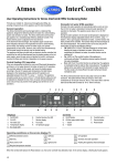
1
Operating Instructions Membrane Metering Pumps Ritmo 033-XX FINK Chem + Tec OHG Hofstraße 9 78073 Bad Dürrheim Tel. 07726-929655 Fax 07726-929656 [email protected] www.finkct.de © Copyright 2011 FINK Chem + Tec OHG, Germany. All rights reserved. 10 th October 2011 Contents Index of contents 1. 1.1 1.2 1.3 1.4 1.5 1.6 Safety instructions Identification of safety instructions in these instructions Qualification and training of personnel Safety instructions for the operator/ user Safety of the system in the event of a failure in the dosing pump Dosing chemicals Safety instructions for service, inspection and mounting 4 4 4 4 5 5 5 2. 2.1 2.2 2.3 2.4 2.5 2.6 General Applications Improper operating methods Warranty Nameplate Type key Device overview 6 6 6 6 7 8 9 3. 3.1 3.2 Technical data / dimensions Technical data Dimensions 10 10, 11 12 4. 4.1 4.1.1 4.1.2 4.1.3 4.1.4 4.2 4.3 Assembly and installation Pump assembly Requirements Align and install mounting plate Engage pump in mounting plate Adjust control cube position Hydraulic connection Electrical connection 13 13 13 13 13 14 14, 15 16 5. 5.1 5.2 5.3 Commissioning Setting the menu language Deaerating the pump Calibrating the pump 18 18 19 19, 20 6. 6.1 6.2 6.2.1 6.2.2 6.2.3 6.2.4 6.3 6.3.1 6.3.2 6.3.3 6.3.4 6.4 6.4.1 6.4.2 6.4.3 6.4.4 6.4.5 6.4.6 6.5 6.6 6.7 6.8 Operation Operating elements Display and symbols Navigation Operating states Sleep mode (energy-saving mode) Overview of display symbols Main menus Operation Info Alarm Setup Operation modes Manual Pulse Analog 0/4 – 20mA Batch (pulse-based) Dosing timer, cycle Dosing timer, week Analog output SlowMode Flow Control Pressure monitoring 21 21 21 21 21 22 22 23 23 23 23 24 24 24 24 25, 26 27 28 29 30 30 31 32 2 6.8.1 6.8.2 6.9 6.10 6.11 6.12 6.13 6.13.1 6.13.2 6.14 6.15 6.16 6.16.1 6.16.2 6.16.3 6.17 Pressure setting ranges Calibration of pressure sensor Flow measurement AutoFlowAdapt Auto deaeration Key lock Display Setup Units Additional display Time/ Date Bus communication Inputs/ outputs Relay outputs External stop Empty and low-level signals Basic settings 32 32, 33 33 33, 34 34 34 35 35 35 36 36 36 36, 37 37 37 37 7. 7.1 7.2 7.2.1 7.2.2 7.2.3 7.3 7.4 Service Service system Perform service Dosing head overview Dismantling the diaphragm and valves Reassembling the diaphragm and valves Resetting the service system Repairs 38 38 39 39 39 39 40 40 8. 8.1 8.1.1 8.1.2 Faults List of faults Faults with error message General faults 40 41 41, 42 43 9. Disposal 43 10. Safety declaration 44 11. EG- Declaration of Conformity 45 3 1. Safety instructions These installation and operating instructions contain general instructions that must be observed during installation, operation and maintenance of the pump. It must therefore be read by the installation engineer and the relevant qualified operator prior to installation and start-up, and must be available at the installation location at all times. Apart from these general safety instructions there are further special instructions in other sections to which attention must be given. The instructions mounted directly on the metering pump must be heeded and always kept in a visible condition. Besides the general safety instructions the operator must consider the existing national regulations for accident prevention as well as the internal working, company, and safety regulations. 1.1 Identification of safety instructions in these instructions The safety instructions are identified by the following symbols: Warning If these safety instructions are not observed, it may result in personal injury! Caution If these safety instructions are not observed, it may result in malfunction or damage to the equipment! Note Notes or instructions that make the job easier and ensure safe operation. 1.2 Qualification and training of personnel The personnel responsible for the installation, operation and service must be appropriately qualified for these tasks. Areas of responsibility, levels of authority and the supervision of the personnel must be precisely defined by the operator. If necessary, the personnel must be trained appropriately. Risks of not observing the safety instructions Non-observance of the safety instructions may have dangerous consequences for the personnel, the environment and the pump and may result in the loss of any claims for damages. It may lead to the following hazards: - Personal injury from exposure to electrical, mechanical and chemical influences. - Damage to the environment and personal injury from leakage of harmful substances. 1.3 Safety instructions for the operator/ user The safety instructions described in these instructions, existing national regulations on health protection, environmental protection and for accident prevention and any internal working, operating and safety regulations of the operator must be observed. Information attached to the pump must be observed. Leakages of dangerous substances must be disposed of in a way that is not harmful to the personnel or the environment. Damage caused by electrical energy must be prevented, see the regulations of the local electricity supply company and the regulations VDE. Caution Before starting work on the pump, the pump must be disconnected from the mains. The system must be pressureless! Only original accessories and original spare parts should be used. Using other parts can result in exemption from liability for any resulting consequences. An existing guards for moving parts must not be removed while the system is in operation. 4 1.4 Safety of the system in the event of a failure in the dosing pump The dosing pump was designed according to the latest technologies and is carefully manufactured and tested. If it fails regardless of this, the safety of the overall system must be ensured. Use the relevant monitoring and control functions for this. Caution Make sure that any chemicals that are released from the pump or any damaged lines do not cause damage to system parts and buildings. The installation of leak monitoring solutions and drip trays is recommended. 1.5 Dosing chemicals Warning Before switching the supply voltage back on, the dosing lines must be connected in such a way that any chemicals in the dosing head cannot spray about and put people at risk. The dosing medium is pressurized and can be harmful to health and the environment. Warning When working with chemicals, the accident prevention regulations applicable at the installation site should be applied (e.g. wearing protective clothing). Observe the chemical manufacturer´s safety data sheets and safety instructions when handling chemicals! Caution Warning If the diaphragm leaks or is broken, dosing liquid will escape from the discharge opening on the dosing head (see fig. 3). Take suitable precautions to prevent harm to health and damage to property from escaping dosing liquid! Check daily whether liquid is escaping from the discharge opening! Changing the diaphragm, see section 7. Service. A deaeration hose, which is routed into a container, e.g. a drip tray, must be connected to the deaeration valve. Caution The dosing medium must be in liquid aggregate state! Observe the freezing and boiling points of the dosing medium! Caution The resistance of the parts that come into contact with the dosing medium, such as the dosing head, valve ball, gaskets and lines, depends on the medium, media temperature and operating pressure. Ensure that parts in contact with the dosing medium are resistant to the dosing medium under operation conditions. Should you have any questions regarding the material resistance and suitability of the pump for specific dosing media, please contact with Fink Chem + Tec OHG 1.6 Safety instructions for service, inspection and mounting The organization is responsible for execution of all service, inspection and mounting work is only done through authorized qualified persons who are instructed with an adequate study of the mounting and operating instructions. Fundamentally, all work on the metering pump is executed only when the pump is not running. The stopping procedure of the pump must be executed as described in the operating instructions. Directly after termination of a process all safety and protection fittings must be placed back into place i.e. set in to function. Before renewed operation all instructions in the section „Putting into operation‟ must be executed. 5 2. General The dosing pump R033 is a self-priming diaphragm pump. It consists of a housing with stepper motor and electronics, a dosing head with diaphragm and valves and the control cube. Excellent dosing features of the pump: - Optimal intake even with degassing media, as the pump always works at full suction stroke volume. - Continuous dosing, as the medium is sucked up with a short suction stroke, regardless of the current dosing flow, and dosed with the longest possible dosing stroke. 2.1 Applications The pump is suitable for liquid, non-abrasive, non-flammable and non-combustible media strictly in accordance with the instructions in these installation and operating instructions. The stated limiting values as shown in the technical data must not be exceeded in any case. Areas of Applikation - Drinking water treatment Wastewater treatment Swimming pool water treatment Boiler water treatment CIP (Clean-In-Place) Cooling water treatment Process water treatment Wash plants Chemical industry Ultrafiltration processes and reverse osmosis Irrigation Paper and pulp industry Food and beverage industries 2.2 Improper operating methods The operational safety of the pump is only guaranteed if it is used in accordance with section 2.1 Applications. Warning Other applications or the operation of pumps in ambient and operation conditions, which are not approved, are considered improper and are not permitted. The Fink Chem + Tec OHG cannot be held liable for any damage resulting from incorrect use. Warning The pump is NOT approved for operation in potentially explosive areas! Warning A sunscreen is required for outdoor installation! 2.3 Warranty A guarantee claim in accordance with our general terms of sale and delivery is only valid if the following requirements are fulfilled: - The pump is used in accordance with the information within this manual. - The pump is not dismantled or incorrectly handled. - The maintenance is carried out by authorised and qualified personnel. - Original spare parts are used for repairs during maintenance. 6 2.4 Nameplate Fig. 1 Nameplate 7 2.5 Type key The type key is used to identify the precise pump and is not used for configuration purposes. Code Example R033 7.5--16 AR- PP/ V/ C- F- 3 1 U2U2 F G * including: 2 pump connections, foot valve, injection unit, 6 m PE discharge hose, 2 m PVC suction hose, 2 m PVC deaeration hose (4/6 mm) 8 2.6 Device overview Control cube Graphic LC display (Sec. 6.2.2) Click wheel (Sect. 6.1) Start/stop key (Sect. 6.1) 100% key (Sect. 6.1) Signal inputs, outputs (Sect. 4.3) Mains connection Mounting plate Fig. 2 Front view of the pump Valve, discharge side Control cube assembly screws Deaeration valve Connection, deaeration hose Dosing head Drain opening in case of diaphragm breakage Valve, suction side FlowControl connection FC/FCM Fig. 3 Rear view of the pump 9 3. Technical data / dimensions 3.1 Technical data Pump type R033Data Turndown ration (setting range) Max. dosing flow Max. dosing flow with SlowMode 50 % Max. dosing flow with SlowMode 25% Min. dosing flow Max. operating pressure Max. stroke frequency Mechanical data Electrical data Signal input 1) Stroke volume Accuracy of repeatability 2) Max. suction lift during operation Max. suction lift when priming with wet 2) valves Min. pressure difference between suction and discharge side Max. pressure, suction side Max. viscosity in SlowMode 25% with 3) spring-loaded valves Max. viscosity in SlowMode 50% with 3) spring-loaded valves Max. viscosity without SlowMode with 3) spring-loaded valves Max. viscosity without spring-loaded 3) valves Min. diameter opf hose/pipe on suction/ 2)4) discharge side Min. diameter of hose/pipe on suction 4) side for highly viscous media (HV) Min. diameter of hose/pipe on discharge 4) side for highly viscous media (HV) Max. media temperature Min. media temperature Max. ambient temperature Min. ambient temperature Max. storage temperature Min. storage temperature Voltage Length of mains cable Max. currrent consumption (100 V) Max. currrent consumption (230 V) Max. power consumption P1 Enclosure class Electrical safety class Max. load for level input Max. load for pulse input Max. load for external stop Min. pulse length Max. pulse frequency Impedance at 0/4-20 mA analog input [1:X] [l/h] [gph] [l/h] [gph] [l/h] [gph] [l/h] [gph] [bar] [psi] [Hübe/ min] [ml] [%] [ml] [m] 7-16 3000 7,5 2,0 3,75 1,00 1,88 0,50 0,0025 0,0007 16 230 190 12-10 1000 12,0 3,1 6,00 1,55 3,00 0,78 0,0120 0,0031 10 150 155 17-7 1000 17,0 4,5 8,50 2,25 4,25 1,13 0,0170 0,0045 7 100 205 30-4 1000 30,0 8,0 15,00 4,00 7,50 2,00 0,0300 0,0080 4 60 180 0,74 1,45 1,55 3,10 3 2 +/-1 6 2 [bar] [bar] [mPas] (=cP) [mPas] (=cP) [mPas] (=cP) [mPas] (=cP) [mm] 3 1 (FC und FCM: 2) 2 2500 2500 2000 1500 1800 1300 1300 600 600 500 500 200 50 300 300 150 4 6 6 9 [mm] 9 [mm] 9 [°C] [°C] [°C] [°C] [°C] [°C] [V] [m] [A] [A] [W] [ms] [Hz] [Ω] 45 -10 45 0 70 -20 100-240 V, 50-60 Hz 1,5 0,18 0,08 5) 18 / 24 IP 65, Nema 4X II 12 V, 5 mA 12 V, 5 mA 12 V, 5 mA 5 100 15 10 Signal input Signal output Weight/ size Sound pressure level Approvals Max. resistance in level circuit Max. resistance in pulse circuit Max. ohmic load on relay output Max. voltage on relay output Impedance at 0/4-20 mA analog output Weight (PVC, PP, PVDF) Weight (stainless steel) Diaphragm diameter Max. sound pressure level [Ω] [Ω] [A] [V] [Ω] [kg] [kg] [mm] [dB(A)] 2,4 3,2 44 1000 1000 0,5 30 VDC/ 30 VAC 500 2,4 3,2 50 60 CE, CSA-US, NSF61, GHOST, C-Tick 1) The maximum stroke frequency varies depending on calibration 2) Data is based on measurements with water 3) Maximum suction lift: 1 m, dosing flow reduced (approx. 30%) 4) Length of suction line: 1.5 m / length of discharge line: 10 m (at max. viscosity) 5) With E- Box 11 2,6 4,0 7,4 3.2 Dimensions Fig.4 Dimensional drawing Pump type A (mm) R033-7-16 280 R033-12-10/17-7 R033-30-4 A1 (mm) B (mm) C (mm) D (mm) 251 196 46,5 24 280 251 200,5 39,5 24 295 267 204,5 35,5 38,5 12 4. Assembly and installation 4.1 Pump assembly The pump is delivered with a mounting plate. The mounting plate can be mounted vertically, e.g. on a wall, or horizontally, e.g. on a tank. It takes just a few quick steps to firmly secure the pump to the mounting plate by means of a slot mechanism. The pump can easily be released from the mounting plate for maintenance. 4.1.1 Requirements - The mounting surface must be stable and must not vibrate. Dosing must flow upwards vertically. 4.1.2 Align and install mounting plate - Vertical installation: Mounting plate slot mechanism must be above. Horizontal installation: Mounting plate slot mechanism must be opposite the dosing head. The mounting plate can be used as a drill template, please see fig. 4 for drill hole distances. Fig. 5 Locate mounting plate Warning Make sure that you do not damage any cables and lines during installation! 1. Indicate drill holes. 2. Drill holes. 3. Secure mounting plate using four screws, diameter 5 mm, to the wall, on the bracket or the tank. 4.1.3 Engage pump in mounting plate 1. Attach the pump to the mounting plate support clamps and slide under slight pressure until it engages. Fig. 6 Engaging the pump 13 4.1.4 Adjust control cube position The control cube is fitted to the front of the pump on delivery. It can be turned by 90° so that the user can select to operate the pump from the right or left side. Caution The enclosure class (IP65 / Nema 4X) and shock protection are only guaranteed if the control cube is installed correctly Caution Pump must be disconnected from the power supply! 1. Carefully remove both protective caps on the control cube using a thin screwdriver 2. Loosen screws. 3. Carefully lift off control cube only so far from the pump housing that no tensile stress is produced on the flat band cable. 4. Turn control cube by 90° and re-attach. - Make sure the O-ring is secure. 5. Tighten screws slightly and attach protective caps. Fig. 7 Adjusting control cube 4.2 Hydraulic connection Warning Risk of chemical burns! Wear protective clothing (gloves and goggles) when working on the dosing head, connections or lines! Caution The dosing head may contain water from the factory check! When dosing media which should not come into contact with water, another medium must be dosed beforehand! Caution Faultless function can only be guaranteed in conjunction with lines supplied by Fink Chem + Tec OHG Caution The lines used must comply with the pressure limits as per section 3.1 Technical data! Important information on installation - Observe suction lift and hose diameter, see section 3.1 Technical data. - Shorten hoses at right angles. - Ensure that there are no loops or kinks in the hoses. - Keep suction line as short as possible. - Route suction line up towards the suction valve. - Installing a filter in the suction line protects the entire installation against dirt and reduces the risk of leakage. 14 - Only control variant FC/FCM: For discharge quantities < 1 l/h we recommend the use of an additional spring-loaded valve (approx 3 bar) on the discharge side for the safe generation of the necessary differential pressure. Hose connection procedure 1. Push union nut and tensioning ring across hose. 2. Push cone part fully into the hose, see fig. 8. 3. Attach cone part with hose to the corresponding pump valve. 4. Tighten union nuts manually - do not use tools! 5. Tighten up union nuts after 2-5 operating hours, if using PTFE gaskets! 6. Attach deaeration hose to the corresponding connection (see fig. 3) and run into a container or a collecting tray. Fig. 8 Hydraulic connection Note Pressure differential between suction and discharge side must be at least 1 bar/14.5 psi! Caution Tighten up the dosing head screws once before commissioning and after 2-5 operating hours at 3 Nm. Installation example The pump offers various installation options. In the picture below, the pump is installed in conjunction with a suction line, level switch and multifunction valve on a Fink Chem + Tec OHG tank Fig. 9 Installation example 15 4.3 Electrical connection Warning The enclosure class (IP65/Nema 4X) is only guaranteed if lugs or protective caps or correctly installed! Warning The pump can start automatically when the mains voltage is switched on! Do not manipulate mains plug or cable! The rated voltage of the pump, see section 2.4 Nameplate, must conform to local conditions. Signal connections Fig. 10 Wiring diagram of the electrical connections 16 FlowControl signal connection Fig.11 FlowControl connection 17 5. Commissioning 5.1 Setting the menu language For description of control elements, see section 6. 1. Turn click wheel to highlight the cog symbol. 2. Press the click wheel to open the ‘Setup‘ menu 3. Turn the click wheel to highlight the „Language‘ menu. 4. Press the click wheel to open the „Language‘ menu. 5. Turn the click wheel to highlight the desired language. 6. Press the click wheel to select the highlighted language. 7. Press the click wheel again to confirm the „Confirm settings„ prompt and apply the setting. Fig. 12 Set menu language 18 5.2 Deaerating the pump Warning The deaeration hose must be connected correctly and inserted into a suitable tank! 1. Open deaeration screw by approximately half turn. 2. Press and hold down the 100% key (deaeration key) until liquid flows continuously without any bubbles from the deaeration hose. 3. Close deaeration screw. Note Press the 100% key and simultaneously turn the click wheel clockwise to increase the duration of the process to up to 300 seconds. After setting the seconds, do not press the key any longer. 5.3 Calibrating the pump The pump is calibrated in the factory for media with a viscosity similar to water rat maximum pump backpressure (see section 3.1 Technical data). If the pump is operated with a backpressure that deviates or if dosing a medium whose viscosity deviates, the pump must be calibrated. For pumps with FCM control variant, it is not necessary to calibrate the pump if there is deviating or fluctuating backpressure as long as the „AutoFlowAdapt‟ function has been enabled (see section 6.10 AutoFlowAdapt). Requirements - The hydraulics and electrics of the pump are connected (see section 4. Assembly and installation). - The pump is integrated into the dosing process under operating conditions. - The dosing head and suction hose are filled with dosing medium. - The pump has been deaerated. 19 Calibration process – example for R033-7-16 1. Fill a measuring beaker with dosing medium. Recommended filling volumes: R033- Typ Medium V1 7-16 0,3 l 12-10 0,5 l 17-7 1,0 l 30-4 1,5 l 2. Read off and note down the fill volume V1 (e.g. 300 ml). 3. Place the suction hose in the measuring beaker. 4. Start the calibration process in the ‘Setup > Calibration‘ menu. 5. The pump executes 200 dosing strokes and displays the factory calibration value (e.g. 125 ml). 6. Remove the suction hose from the measuring beaker and check the remaining volume V2 (e.g. 170 ml). 7. From V1 and V2, calculate the actual dosed volume Vd=V1-V2 (e.g. 300 ml – 170 ml = 130 ml). 8. Set and apply Vd in the calibration menu. - The pump is calibrated. 20 6. Operation 6.1 Operating elements The pump control panel includes a display and the following control elements. Fig. 13 Control panel Key Start/stop key 100% key Function Starting and stopping the pump. The pump doses at maximum flow regardless of the operation mode. Click wheel The click wheel is used to navigate through the menus, select settings and confirm them. Turning the click wheel clockwise moves the cursor clockwise in increments in the display. Moving your finger anti-clockwise moves the cursor anti-clockwise. 6.2 Display and symbols 6.2.1 Navigation In the ‘Info‘, ‘Alarm‘ und ‘Setup„ main menus, the options and submenus are displayed in the rows below. Use the „Back‟ symbol to return to the higher menu level. The scroll bar at the right edge of the display indicates that here are further menu items which are not shown. The active symbol (current cursor position) flashes. Press the click wheel to confirm your selection and open the next menu level. The active main menu is displayed as text, the other main menus are displayed a symbols. The position of the cursor is highlighted in black in the sub-menus. When you position the cursor on a value and press the click wheel, a value is selected. Turning the click wheel clockwise increases the value, turning the click wheel anti-clockwise reduces the value. When you now press the click wheel, the cursor will be released again. 6.2.2 Operating states The operating state of the pump is indicated by a symbol and display colour. 21 6.2.3 Sleep mode (energy-saving mode) If in the ‘Operation‘ main menu the pump is not operated for 30 seconds, the header disappears. After 2 minutes, the display switches to the „Operation‟ main menu and the display brightness is reduced. This state will be cancelled when the pump is operated or a fault occurs. 6.2.4 Overview of display symbols The following display symbols may appear in the menus. Fig. 14 Overview of display symbols 22 6.3 Main menus The main menus are displayed as symbols at the top of the display. The currently active main menu is displayed as text. 6.3.1 Operation Status information such as the dosing flow, selected operation mode and operating state is displayed in the „Operation‘ main menu. 6.3.2 Info You can find the date, time and information about the active dosing process, various counters, product data and the service system status in the „Info‟ main menu. The information can be accessed during operation. The service system can also be reset form here. 6.3.3 Alarm You can view errors in the „Alarm‘ main menu. Up to 10 warnings and alarms, together with their date, time and cause, are listed in chronological order. If the list is full, the oldest entry will be overwritten, see Section 8. Faults. 23 6.3.4 Setup The ‘Setup‘ main menu contains menus for pump configuration. These menus are described in the following sections. *These submenus are only displayed for specific default settings and control variants. The contents of the „Setup’ menu also vary depending on the operation mode. 6.4 Operation modes Six different operation modes can be set in the „Setup > Operation mode’ menu. - - Manual, see section 6.4.1 Pulse, see section 6.4.2 Analog 0-20 mA, see section 6.4.3 Analog 4-20 mA, see section 6.4.3 Batch, see section 6.4.4 Dosing timer, cycle see section Kap. 6.4.5 Dosing timer, week see section Kap. 6.4.6 6.4.1 Manual In this operation mode, the pump constantly doses the dosing flow set with the click wheel. The dosing flow is set in l/h or ml/h. The pump automatically switches between the units. Alternatively, the display can be reset to US units (gph). Fig. 15 Manual mode The setting range depends on the pump type: Setting range* Type l/h gph R033-7-16 0,0025 – 7,5 0,0007 – 2,0 R033-12-10 0,012 – 12,0 0,0031 – 3,1 R033-17-7 0,017 – 17,0 0,0045 – 4,5 R033-30-4 0,03 - 30 0,0080 – 8,0 *When the SlwoMode function is active, the maximum dosing flow is reduced, see section 3.1 Technical data. 24 6.4.2 Pulse In this operation mode, the pump doses the set dosing volume for each incoming (potential-free) pulse, e.g. from a water meter. There is no direct connection between incoming pulses and dosing strokes. The pump automatically calculates the optimum stroke frequency for dosing the set volume per pulse. The calculation is based on: - the frequency of external pulses - the set dosing volume/pulse. Fig. 16 Pulse operation mode The dosing volume per pulse is set in ml/pulse using the click wheel. The setting range for the dosing volume depends on the pump type Type R033-7-16 R033-12-10 R033-17-7 R033-30-4 Setting range/pulse 1,3µl - 12,8 ml 2,6µl - 25,8 ml 2,7µl - 26,8 ml 5,8µl - 58,4 ml The frequency of incoming pulses is multiplied by the set dosing volume. If the pump receives more pulses than it can process at the maximum dosing flow, it runs at the maximum stroke frequency in continuous operation. Excess pulses will be ignored if the memory function is not enabled. Memory- function When the „Setup > Pulse memory„ function is enabled, up to 65,000 unprocessed pulses can be saved for subsequent processing. Note The contents of the memory will be deleted when: - switching off the power supply - switching the operating mode - the pump is interrupted (e.g. alarm, external stop.) 6.4.3 Analog 0/4 – 20 mA In this operation mode, the pump doses according to the external analog signal. The dosing volume is proportional to the signal input value in mA. If the input value in operation mode 4-20 mA falls below 2 mA, an alarm is displayed and the pump stops. A cable break or signal transmitter error has occurred. The „Cable break’ symbol is displayed in the „Signal and error display’ area of the display. 25 Fig. 17 Analog scaling Fig. 18 Analog operation mode Set analog scaling Analog scaling refers to the assignment of the current input value to the dosing flow. Analog scaling passes through the two reference points (I1/Q1) and I2/Q2), which are set in the ‘Setup > Analog scaling’ menu. The dosing flow is controlled according to this setting. Example 1 (R033-7-16) Analog scaling with positive gradient: Fig. 19 Analog scaling with pos. gradient In example 1, the reference points I1=6 mA,Q1=1,5l/h and I2=16 mA, Q2=7,5 l/h have been set. From 0 to 6 mA analog scaling is described by a line that passes through Q=0 l/h, between 6 mA and 16 mA it rises proportionally from 1.5 l/h to 7.5 l/h and from 16 mA onwards it passes through Q=7.5 l/h. Example 2 (R033-7-16) Analog scaling with negative gradient (Operation mode 0-20 mA): Fig. 20 Analog scaling with neg. gradient. 26 In example 2, the reference points I1=2 mA, Q1=7,5 l/h and I2=16 mA, Q2=1,3 l/h have been set. From 0 to 2 mA analog scaling is described by a line that passes through Q=0 l/h, between 2 mA and 16 mA it drops proportionally from 7.5 l/h to 1.3 l/h and from 16 mA onwards it passes through Q2=1.3 l/h. Set analog scaling in the ’Operation‘ menu Analog scaling can also be modified after a security prompt directly in the „Operation‟ menu. This is how the dosing flow is directly modified for the current flow input value. Caution Please observe that changes also have a direct effect on point I2/Q2 (see fig. 21)! Fig. 21 Set analog scaling („Operation„ menu) 6.4.4 Batch (pulse-based) In this operation mode, the pump doses the set batch volume in the set dosing time (T1). A batch is dosed with each incoming pulse. Fig. 22 Batch (pulse-based) The setting range depends on the pump type: Setting range per batch Type R033-7-16 R033-12-10 R033-17-7 R033-30-4 from (ml) 0,74 1,45 1,55 3,10 to(l) 999 999 999 999 Resolution* (ml) 0,0925 0,1813 0,1938 0,3875 *Thanks to the digital motor control, dosing quantities with a resolution of up to 1/8 of the dosing stroke volume can be dosed. The batch volume (e. g. 75 ml) is set in the „Setup > Batch volume’ menu. The minimum dosing time required for this (e. g. 32 seconds) is displayed and can be increased. Fig. 23 Batch mode 27 If the batch volume is modified, the dosing time resets to the minimum dosing time. Signals received during a batch process or an interruption (e. g. alarm, external stop) will be ignored. If the pump is restarted following an interruption, the next batch volume is dosed on the next incoming pulse. Fig. 24 Batch mode In the „Operation‟ menu, the total batch volume (e. g. 75 ml) and the remaining batch volume still to be dosed (e.g. 43 ml) are shown in the display. 6.4.5 Dosing timer, cycle In this operation mode, the pump doses the set batch volume in regular cycles. Dosing starts when the pump is started after a singular star delay. The setting range for the batch volume corresponds to the values in section 6.4.4 Batch (pulse-based). Fig. 25 Dosing Timercycle T1 T2 T3 Dosing time Start delay Cycle time The cycle time must e longer than the dosing time, otherwise the following dosing will be ignored. In the event of an interruption (e. g. interruption of the mains voltage, external stop), the dosing will be stopped while the time continues running. After suspending the interruption, the pump will continue to dose according to the actual timeline position. The following settings are required in the „Setup > Dos. Timer Cycle’ menu: Fig. 26 Dos. Timer Cycle mode The batch volume to be dosed (e. g. 125 ml) is set in the „Setup > Dos. Timer Cycle’ menu. The minimum dosing time required for this (e. g. 1:54) is displayed and can be increased. The total batch volume (e. g. 125) ml) and the remaining batch volume still to be dosed are displayed in the ‘Operation’ menu. During breaks in dosing, the time until the next dosing process (e. g. 1:21) is displayed. 28 Fig. 27 Dos. Timer Cycle mode 6.4.6 Dosing timer, week In this operation mode, up to 16 dosing procedures are defined for a week. These dosing procedures may take place regularly on one of several week days. The setting range for the batch volume corresponds to the values in section 6.4.4 Batch (pulse-based). Fig. 28 Week timer dosing Note If several procedures overlap, the process with the higher dosing flow has priority! In the event of an interruption (e. g. disconnection of the mains voltage, external stop), the dosing is stopped while the time continues running. After suspending the interruption, the pump continues to dose according to the actual timeline position. The following settings are required in the ‘Setup > Dos. Timer Week’ menu for each dosing procedure: Fig. 29 Setting the timer The batch volume (e. g. 80.5 ml) is set in the ‘Setup > Dos. Timer Week’ menu. The minimum dosing time required for this (e. g. 0:34) is displayed and can be increased. In the Operation mode, the total batch volume (e. g. 80.5 ml) and the remaining batch volume to be dosed is displayed. During breaks in dosing, the time (e. g. 43:32) until the next dosing is displayed. Fig. 30 Weekly timer dosing/break in dosing 29 6.5 Analog output Fig. 31 Configure analog output The analog output of the pump is parametrised in the „Setup > Analog output„ menu. The following setting are possible: Setting Output=Input Actual flow Backpressure Bus control Description Analog output signal The analog input signal is mapped 1:1 to the analog output (e. g. to control several pumps using one signal) Current actual flow - 0/4 mA = 0% 20 mA = 100% See section 6.8.2 Calibration of pressure sensor Backpressure, measured in the dosing head - 0/4 mA = 0% 20 mA = 100% See section 6.8 Pressure monitoring Enabled by command in Bus control, see section 6.15 Bus communication FCM Control variant FC X X X X X* X* X X X X AR X *Output signal is based on motor speed and pump status (target flow). Wiring diagram see section 4.3 Electrical connection. Note In all modes, the analog output has a range of 4-20 mA. Exception: Operation mode 0-20 mA. Here, the analog output range is 0-20 mA. 6.6 SlowMode When the „SlowMode‘ function is enabled, the pump slows down the suction stroke. The function is enabled in the „Setup > SlowMode‘ menu and is used to prevent cavitation in the following cases: - for dosing media with a higher viscosity - for degassing dosing media - for long suction lines - for large suction lift In the „Setup > SlowMode‘ menu, the speed of the suction stroke can be reduced to 50% or 25%. Caution Enabling the ‘SlowMode‘ function reduces the maximum dosing flow of the pump to the set percentage value! Fig. 32 SlowMode menu 30 6.7 Flow Control FC/FCM control variant. This function is used to monitor the dosing process. Although the pump is running, various influences e. g. air bubbles, can cause a reduced flow or even stop the dosing process. In order to guarantee optimum process safety, the enabled FlowControl function directly detects and indicates the following errors and deviations: - Overpressure - Damaged discharge line - Air in the dosing chamber - Cavitation - Suction valve leakage - Discharge valve leakage The occurrence of a fault is indicated by the „eye„ symbol flashing. The faults are displayed in the „Alarm‟ menu (see section 8.Faults). FlowControl works with a maintenance-free sensor in the dosing head. During the dosing process, the sensor measures the current pressure and continuously sends the measured value to the microprocessor in the pump. An internal indicator diagram is created from the current measured values and the current diaphragm position (stroke length). Causes for deviations can be identified immediately by aligning the current indicator diagram. Air bubbles in the dosing head reduce e. g. the discharge phase and consequently the stroke volume (see fig. 33). Fig. 33 Indicator diagram 1) Compression phase 2) Discharge phase 3) Expansion phase 4) Suction phase Setting FlowControl The „FlowControl‘ function is set using the two parameters „Sensitivity„ and „Delay‘ in the „Setup > FlowControl„ menu. Sensitivity In ‘Sensitivity„ the deviation in stroke volume, which will result in an error message, is set in percent. Sensitivity Low Medium High Deviation approx. 70% approx. 50% approx. 30% 31 Delay The ‘Delay„ parameter is used to define the time period until an error message is generated: „short‘ „medium„ or ‘long„. The delay depends on the set dosing flow and therefore cannot be measured in strokes or time. 6.8 Pressure monitoring FC/FCM control variant. A pressure sensor monitors the pressure in the dosing head. If the pressure during the discharge phase falls below 2 bar, a warning is generated (pump continues running). If in the ‘Setup > Pressure monitoring’ menu the function „Min. pressure alarm’ is activated, an alarm is generated and the pump is stopped. If the pressure exceeds the cut-off pressure set in the „Setup > Pressure monitoring„ menu, the pump is shut down, enters the standby state and indicates an alarm. Caution The pump restarts automatically once the backpressure falls below the cut-off pressure! 6.8.1 Pressure setting ranges Type R033-7-16 R033-12-10 R033-17-7 R033-30-4 Caution Fixed min. pressure (bar) <2 <2 <2 <2 Settable max. pressure (bar) 3…17 3…11 3 8 3 5 The pressure measured in the dosing head is slightly higher than the actual system pressure. Therefore the cut-off pressure should be set min. 0.5 bar higher than the system pressure. Warning Install a pressure-relief valve in the pressure line to provide protection against impermissibly high pressure! 6.8.2 Calibration of pressure sensor The pressure sensor is calibrated in the factory. As a rule, it does not need to be re-calibrated. If specific circumstances (e. g. pressure sensor exchange, extreme air pressure values at the location of the pump) necessitate a calibration, the sensor can be calibrated as follows. 1. Set pump to „Stop’ operational state. 2. Make system pressureless and flush. 3. Dismantle suction line and suction valve. Caution Calibrating when the suction valve is installed produces incorrect calibration and can cause personal injuries and damage to property! Only carry out a calibration if this is technically required! 32 4. Proceed as described below to calibrate: If a calibration is not successfully possible, check plug connections, cable and sensor and replace defective parts where necessary. 6.9 Flow measurement FCM control variant. The pump accurately measures the actual flow and displays it. Via the 0/4 – 20 mA analog output, the actual flow signal can easily be integrated into an external process control without additional measuring equipment (see section 6.5 Analog output). The flow measurement is based on the indicator diagram as described in section 6.7 FlowControl. The accumulated length of the discharge phase multiplied by the stroke frequency produces the displayed actual flow. Faults e. g. air bubbles or backpressure that is too low result in a smaller or larger actual flow. When the ‘AutoFlowAdpat’ function is activated (see section 6.10 AutoFlowAdapt), the pump compensates for these influences by correction of the stroke frequency. Note Strokes which cannot be analysed (partial strokes, pressure differential which is too low) are provisionally calculated based on the setpoint value and displayed. 6.10 AutoFlowAdapt FCM control variant. The ‘AutoFlowAdapt„ function is activated in the „Setup„ menu. It detects changes in various parameters and responds accordingly in order to keep the set target flow constant. Note Dosing accuracy is increased when ‘AutoFlowAdapt‘ is activated. This function processes information from the pressure sensor in the dosing head. Errors detected by the sensor are processed by the software. The pump responds immediately regardless of the 33 operation mode by adjusting the stroke frequency or where necessary compensating for the deviations with a corresponding indicator diagram. If the target flow cannot be achieved by the adjustments, a warning is issued. ‘AutoFlowAdapt„ operates on the basis of the following functions: - FlowControl: malfunctions are indentified (see section 6.7 FlowControl). - Pressure monitoring: pressure fluctuations are identified (see section 6.8 Pressure monitoring) - Flow measurement: deviations from the target flow are indentified (see section 6.8.2 Calibration of pressure sensor). Examples of ‘AutoFlowAdapt‘ Pressure fluctuations The dosing volume decreases as backpressure increases and conversely the dosing volume increases as the backpressure decreases. The ‘AutoFlowAdapt„ function identifies pressure fluctuations and responds by adjusting the stroke frequency. The actual flow is thus maintained at a constant level. Air bubbles The ‘AutoFlowAdapt„ function identifies air bubbles, The pump responds with a special indicator diagram due to which the air bubbles are removed as a top priority (deaeration). If the air bubbles have not been eliminated after a maximum of 60 strokes, the pump switches to the ‚Air bubble„ warning status and returns to the normal indicator diagram. 6.11 Auto deaeration Dosing degassing media can result in air pockets in the dosing head during breaks in dosing. This can result in no medium being dosed when restarting the pump. The „Setup > Auto deaeration’ function performs pump deaeration automatically at regular intervals. Software-controlled diaphragm movements encourage any bubbles to rise and gather at the discharge valve so that they can be removed on the next dosing stroke. The function works: - when the pump is not in the „Stop„ mode. - during breaks in dosing (e. g. External stop, no incoming pulses, etc.). Note Low volumes can be displaced into the discharge line by the diaphragm movements. When dosing strongly degassing media, this is however virtually impossible. 6.12 Key lock The key lock is set in the ‘Setup > Key lock„ menu by entering a four-digit code. It protects the pump by preventing changes to settings. Two levels of key lock can be selected: Level Settings Settings + keys Description All settings can only be changed by entering the lock code. The start/stop key and the 100% key are not locked. The start/Stop key and the 100% key and all settings are locked. It is still possible to navigate in the ‘Alarm‘ and ‘Info‘ main menu and reset alarms. Temporary deactivation If the key lock function is activated but settings need to be modified, the keys can be unlocked temporarily by entering the deactivation code. If the code is not entered within 10 seconds, the display automatically switches to the ‘Operation„ main menu. The key lock remains active. Deactivation The key lock can be deactivated in the ‘Setup > Key lock‘ menu via the „Off‘ menu point. The key lock is deactivated after the general code ‘2583’ or a predefined custom code has been entered. 34 6.13 Display Setup Use the following settings in the ‘Setup > Display‘ menu to adjust the display properties: - Units (metric/US) - Display contrast - Additional display 6.13.1 Units Metric units (liters/milliliters/bar) or US units (US gallons/PSI) can be selected. According to the operation mode and menu, the following units of measurement are displayed: 6.13.2 Additional display Additional display provides additional information about the current pump status. The value is shown in the display with the corresponding symbol. In ‘Manual‘ mode the ’Actual flow„ information can be displayed with Q = 1.28 l/h (see fig. 34). Fig. 34 Display with additional display The additional display van be set as follows: 1) only R033-FCM control variant 2) only R033-FCM/FC control variant 35 6.14 Time/ Date The time and date can be set in the „Setup > Time + date„ menu. Caution The conversion between summer and winter time does not take place automatically! 6.15 Bus communication The pump is supplied with an integrated module for GENIbus communication. The pump identifies the bus control after connecting to the corresponding signal input. The “Activate Genibus”? prompt is displayed. After confirmation, the ‘Bus’ submenu appears in the „Setup’ menu. Fig. 35 „Setup > Bus„ menu The corresponding symbol appears in the „Activated functions„ area in the ‚Operation„ menu. The pump can also be integrated into a Profibus DP network using the additional E-box module (retrofitting possible). The bus communication enables remote monitoring and setting of the pump via a fieldbus system. 6.16 Inputs/outputs In the „Setup > Inputs/outputs‘ menu, you can configure the two outputs „Relay 1+2‘ and the signal inputs „External stop‘, ‘Empty signal„ and „Low level signal‘: Fig. 36 „Setup > Inputs/outputs„ menu 6.16.1 Relay outputs The pump can switch two external signals using installed relays. The relays are switched by potential free pulses. The connection diagram of the relays is shown in section 4.3 Electrical connection. Both relays can be allocated with the following signals. Relay 1 signal Alarm* Relay 2 signal Alarm Warning* Warning Stroke signal Pump dosing Bus control Stroke signal* Pump dosing Bus control Contact type NO* NC Timer, cycle Timer, week Description Display red, pump stopped (e.g. empty signal, etc.) Display yellow, pump is running (e.g. low-level signal, etc.). Each full stroke Pump running and dosing Activated by a command in the bus communication See following section See following section NO* NC Normally open contact Normally closed contact *Factory setting 36 Timer, cycle (relay 2) For the ‘Relay 2 > Timer cycle„ function, set the following parameters: - Dosing time (t1) - Start delay (t2) - Cycle time (t3) Abb. 37 Diagram Timer Week (Relay 2) - This function saves up to 16 relay on-times for a week. The following settings can be made for each relay switching operation in the „Relay 2 > Timer Week’ menu: - Procedure (No.) - On-time (duration) - Start time - Weekdays. 6.16.2 External Stop The pump can be stopped via an external pulse, e.g. from a control room. When activating the external stop pulse, the pump switches from the operational state „Running‟ into the operational state ‘Standby’. The corresponding symbol appears in the Signal/error display (see section 6.2.2 Operating states). Caution Frequent disengagement from the mains voltage, e.g. via a relay, can result in damage to the pump electronics and to the breakdown of the pump. The dosing accuracy is also reduced as a result of internal start procedures. Do not control the pump via the mains voltage for dosing purposes! Only use the ‘External stop’ function to start and stop the pump! The contact type is factory-set to closing contact (=>NO). In the „Setup > Inputs/outputs > External stop‘ menu, the setting can be changed to opening contact (=>NC) 6.16.3 Empty and low-level signals In order to monitor the fill level in the tank, a dual-level control unit can be connected to the pump. The pump responds to the signals as follows: Both signal inputs are allocated to the closing contact (=>NO) in the factory. They can be re-allocated in the ‘Setup > Inputs/outputs‘ menu to opening contact (=>NC). 6.17 Basic settings All settings can be reset to the settings default upon delivery in the ‘Setup > Basic settings‘ menu. Selecting ’Save customer settings„ saves the current configuration to the memory. This can then be activated using ’Load customer settings‘. The memory always contains the previously saved configuration. Older memory data is overwritten. 37 7. Service In order to ensure a long service life and dosing accuracy, wearing parts such as diaphragms and valves must be regularly checked for signs of wear. Where necessary, replace worn parts with original spare parts made from suitable materials. Should you have any questions, please contact with us. Warning If the diaphragm leaks or is broken, dosing liquid will escape from the discharge opening on the dosing head (see fig. 3). Take suitable precautions to prevent harm to health and damage to property caused by escaping dosing liquid! Check daily whether liquid is escaping from the discharge opening! 7.1 Service system According to the motor runtime service requirements will appear. Service requirements appear regardless of the current operational state of the pump and do not affect the dosing process. Service requirement ‘Service soon„ Motor runtime (h)* 7.500 Time interval (months)* 23 ‘Service now„ 8.000 24 *Since the last service system reset Fig. 38 „Service soon„ Fig. 39 „Service now„ The service requirement signals when the replacement of wearing parts is due and displays the number of the service kit. Press the click wheel to temporarily hide the service prompt. When the „’Service now’ message appears (displayed daily), the pump must be serviced immediately. To signalise in the „Operation’ menu, the Symbol appears in the ’Signal/error display„ area of the display. The number of the service kit required is also displayed in the ‘Info’ menu. For media which result in increased wear, the service interval must be shortened. 38 7.2 Perform service Only spare parts and accessories from Fink Chem + Tec OHG should be used for maintenance. The usage of non-original spare parts and accessories renders any liability for resulting damages null and void. Warning When dosing dangerous media, observe corresponding precautions in the safety data sheets! Risk of chemical burns! Wear protective clothing (gloves and goggles) when working on the dosing head, connections or lines! Do not allow any chemicals to leak from the pump. Collect and dispose of all chemicals correctly! Caution Before any work to the pump, the pump must be disconnected from the mains. The system must be pressureless! 7.2.1 Dosing head overview 1 2 3 4 5 6 7 8 9 10 Safety diaphragm Flange O-ring Diaphragm Valve on discharge side Valve on suction side Dosing head Screws with discs Cover Deaeration valve Fig. 40 Dosing head, exploded view 7.2.2 Dismantling the diaphragm and valves 1. 2. 3. 4. 5. 6. 7. 8. 9. 10. 11. Make system pressureless. Empty dosing head before maintenance and flush it if necessary. Set pump to „Stop„ operational state using the ’Start/stop key„ Press the „Start/stop‘ and „100%„ keys at the same time to put the diaphragm into ‟out‘ position. - Symbol must be displayed as the operational state (see fig. 13). Take suitable steps to ensure that the returning liquid is safely collected. Dismantle suction, pressure and deaeration hoses. Dismantle valves on suction and discharge side (5, 6). Remove the cover (9). Loosen screws (8) on the dosing head (7) and remove the screws and discs. Remove the dosing head (7). Unscrew diaphragm (4) counter-clockwise and remove with flange (2) 7.2.3 Reassembling the diaphragm and valves 1. Attach flange (2) correctly and screw on new diaphragm (4) clockwise. - Make sure that the O-ring (3) is seated correctly! 2. Press the ‘Start/stop’ and „100%‟ keys at the same time to put the diaphragm into „in‟ position. - Symbol must be displayed as the operational state (see fig. 13). 3. Attach the dosing head (7). 4. Install screws with discs (8) and cross-tighten. - Torque: 3 Nm. 5. Attach the cover (9). 6. Install new calves (5, 6). - Do not interchange valves and pay attention to direction of arrow. 7. .Connect suction, pressure and deaeration hose (see section 4.2 Hydraulic connection) 8. Press the „Start/Stop’ key to leave the service mode. 9. Deaerate dosing pump (see section 5.2 Deaerating the pump). 10. Please observe the notes on commissioning in section 5. Commissioning! 39 7.3 Resetting the service system After performing the service, the service system must be reset using the ‘Info > Reset service system’ function. 7.4 Repairs Warning The pump housing must only be opened by personnel authorised by Fink Chem + Tec OHG! Repairs must only be carried out by authorised and qualified personnel! Switch off the pump and disconnect it form the voltage supply before carrying out maintenance work and repairs! After consulting Fink Chem + Tec OHG, please send the pump, together with the safety declaration completed by a specialist, to Fink Chem + Tec OHG. The safety declaration can be found at the end of these instructions. It must be copied, completed and attached to the pump. Caution If the pump has been used to dose toxic liquids or liquids hazardous to health, the pump must be cleaned prior to dispatch! If the above requirements are not met, the Fink Chem + Tec OHG may refuse to accept delivery of the pump. The shipping costs will be charged to the sender. 8. Faults In the event of faults in the dosing pump, a warning or an alarm is triggered. The corresponding fault symbol flashes in the „Operation’ menu, see section 8.1 List of faults. The cursor jumps to the „Alarm‟ main menu symbol. Press the click wheel to open the „Alarm‟ menu and, where necessary, faults to be acknowledged will be acknowledged. A yellow display indicates a warning and the pump continues running. A red display indicates an alarm and the pump is stopped. The last 10 faults are stored in the ‘Alarm„ main menu. When a new fault occurs, the oldest fault is deleted. The two most recent faults are shown in the display, you can scroll through all the other faults. The time and cause of the fault are displayed. The list of faults can be deleted at the end of the list. If there is a service requirement, this appears when the „Alarm’ menu is opened. Press the click wheel to temporarily close the service prompt (see section 7.1 Service system). 40 8.1 List of faults 8.1.1 Faults with error message Display in the ‘Alarm‘ menu Empty (Alarm) Low level (Warning) Overpressure (Alarm) Possible cause Dosing medium tank empty Dosing medium tank almost empty Discharge valve blocked Isolating valve in discharge line closed Pressure peaks due to high viscosity „Max. pressure„ set too low (see section 6.8 Pressure monitoring) Possible remedy Fill tank Check contact setting (NO/NC) Replace valve if necessary (see section 7.2 Perform service) Check flow direction of valves (arrow) and correct if necessary. Open the isolating valve (on the discharge side). Enlarge diameter of discharge line. Change pressure setting (see section 6.8 Pressure monitoring). Change the diaphragm (see section 7.2 Perform service). Check discharge line and repair if necessary. Install additional springloaded valve (approx. 3 bar) on the discharge side. Close the deaeration valve. Check suction line and repair if necessary. Provide positive inlet pressure (place dosing medium tank above the pump). Enable „Slow Mode’ (see section 6.6 SlowMode). Fill tank. Enable „Slow Mode„ (see section 6.6 SlowMode) Reduce suction lift. Increase suction hose diameter Check suction line and open isolating valve if necessary. Check valve and tighten it up. Flush system. Replace valve if necessary (see section 7.2 Perform service). Check O-ring position. Install filter in suction line. Close the deaeration valv 41 Backpressure low (Warning/alarm*) Faulty diaphragm Broken discharge line Pressure differential between suction and discharge side toot low Leakage in the pressure retention valve at Q > 1 l/h Deaeration valve open Broken/leaky suction line Strongly degassing medium Tank dosing medium empty Air bubble (Warning) Cavitation (Warning) Blocked/constricted/squeezed suction line Blocked/constricted suction valve Suction lift too high Viscosity too high Suct. valve leak (Warning) Leaky/dirty suction valve Deaeration valve open Disch. valve leak (Warning) Leaky/dirty discharge valve Leakage in the pressure retention valve Deaeration valve open Flow deviation (Warning) Considerable deviation between target and actual flow Pump no / incorrectly calibrated Broken FlowControl cable Sensor defect Pressure sensor not correctly calibrated. Backpressure greater than nominal pressure Damage to gears Fieldbus communication error Pressure sensor (Warning) Motor blocked (Alarm) Bus (Warning/alarm*) E-Box (Alarm) E-Box connection error Faulty E-Box Cable break (Alarm) Defect in analog cable 4-20 mA (input current < 2 mA) Service soon/now (Warning) Time interval for service expired Check valve and tighten it up. Flush system. Replace valve if necessary (see section 7.2 Perform service). Check O-ring position. Install screen in suction line Close the deaeration valve. Install spring-loaded valve on the discharge side. Check installation Calibrate the pump (see section 5.3 Calibrating the pump) Check plug connection. Change sensor if necessary. Calibrate pressure senor correctly (see section 6.8.2 Calibration of pressure sensor). Reduce backpressure. Arrange for repair of gears, if necessary. Check cables for correct specification and damage; replace if necessary. Check cable routing and shielding; correct if necessary. Check plug connection Replace E- Box if necessary. Check cable/plug connections and replace, if necessary. Check signal transmitter. Perform service (see section 7.2 Perform service) * Depending on setting 42 8.1.2 General faults Fault Dosing flow too high Possible cause Inlet pressure greater than backpressure Incorrect calibration No dosing flow or dosing flow too low Air in dosing head Faulty diaphragm Leakage/fracture in lines Valves leaking or blocked Valves installed incorrectly Blocked suction line Suction lift too high Viscosity too high Pump outside the calibration Irregular dosing Deaeration valve open Valves leaking or blocked Backpressure fluctuations Liquid escaping from the discharge opening on the flange Liquid escaping Pump not sucking in Faulty diaphragm Dosing head screws not screwed in as far as they will go Valves not screwed in as far as they will go Suction lift too high Backpressure too high Soiled valves Possible remedy Install additional spring-loaded valve (approx. 3 bar) on the discharge side. Increase pressure differential. Calibrate the pump (see section 5.3 Calibrating the pump). Deaerate the pump Change the diaphragm (see section 7.2 Perform service). Check and repair lines. Check and clean valves. Check that the arrow on the valve housing is pointing in the direction of low. Check whether all O-rings are installed correctly. Clean suction line/install filter. Reduce suction lift. Install priming aid. Enable ‘Slow Mode‘ (see section 6.6 SlowMode). Enable ‘Slow Mode (see section 6.6 SlowMode). Use hose with larger diameter. Install spring-loaded valve on the discharge side. Calibrate the pump (see section 5.3 Calibrating the pump). Close the deaeration valve. Tighten up valves, replace valves if necessary (see section 7.2 Perform service). Keep backpressure constant. ‘AutoFlowAdapt„ activate (only FCM). Change the diaphragm (see section 7.2 Perform service). Tighten up screws (see section 4.2 Hydraulic connection). Tighten up valves/union nuts (see section 4.2 Hydraulic connection). Reduce suction lift, if necessary provide positive inlet pressure. Open the deaeration valve. Flush system, replace valves if necessary (see section 7.2 Perform service). 9. Disposal This product and all its associated parts must be disposed of in an environmentally friendly manner. Use appropriate waste collection services. If there is no such facility or the facility refuses to accept these materials used in the product, the product can be sent to the Fink Chem + Tec OHG. 43 Appendix Safety declaration Please copy, fill in and sign this sheet and attach it to the pump returned for service. Product type (nameplate ______________________________________ Model- number (nameplate ______________________________________ Dosing medium _______________________________________ Fault description Please make a circle around the damaged parts. In the case of an electrical or functional fault, please mark the cabinet. Please describe the error / cause of the error in brief. We hereby declare that the pump has been cleaned and is completely free from chemical, biological and radioactive substances. __________________________________ Date, signature and Company stamp 2012 Fink Chem + Tec OHG The texts, images and examples in this manual are carefully compiled. Fink Chem + Tec OHG is not liable for possible remaining incorrect details and following consequences or breach of other third party rights neither legal responsibility nor other liability. We are thankful for any notifications or improvement suggestions. The material, Soft and Hardware terms and names mentioned in this manual are usually registered trademarks and underlie the legal regulations. The manual protected by copyright. All rights reserved. No part of this manual may be reproduced by photo copy, microfilm or other means or transferred to machines, especially data processing equipment, in the appropriate language. Presentation by submission in lectures, radio and television is allowed only with our written consent. 44 EG - Declaration of Conformity Machinery Directive 2006/42/EG, II 1, A Membrane Metering Pumps R 033-xxx Manufacturer Fink Chem+Tec OHG Hofstraße 9 D-78073 Bad Dürrheim We declare that this delivered R 033/DDA Metering Pump and in all versions are in conformity with the following standards or standardized documents according to the provisions of the directives of the EC state members. – Machinery Directive (2006/42/EG). Standards used: EN 809: 1998 EN ISO 12100-1+A1: 2009 EN ISO 12100-2+A1: 2009 – EMC Directive (2004/108/EG). Standards used: EN 61000-6-2: 2005, EN 61000-6-4: 2007 – Low Voltage Directive (2006/95/EG). Standard used: EN 60204-1+A1: 2009 – Electrical equipment applicated within specified voltage ranges Norm EN 61 010 -1 und EN 61 010-2-010/A1 Person authorised to compile technical file and empowered to sign the EC declaration of conformity. Manufacturer/Supplier Grundfos/Fink Chem+Tec OHG D. Fink Date 06.09.2011 45