1
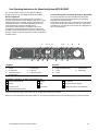
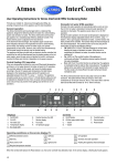
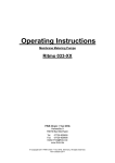
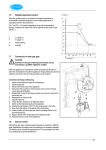
Atmos
InterSystem
User Operating Instructions for HE26 & HE40C
(GC 41-249-05 & GC 41-249-07)
Atmos Heating Systems
West March
Daventry
Northants, NN11 4SA
Tel: 01327 871990
Fax: 01327 871905
e-mail: [email protected]
internet: www.atmos.co.uk
Issue 1.11.11 (Main revision)
© 2011 Atmos Heating Systems
The information provided applies to the product in the
standard model. Atmos Heating Systems can therefore not
be held liable for any damage resulting from the product
specifications that deviate from the standard model.
The information provided has been compiled with the utmost
care. However, Atmos Heating Systems cannot be held
liable for any faults in the information nor for the
consequences thereof. Atmos Heating Systems cannot be
held liable for any damage resulting from the activities
carried out by third parties.
To be changed without prior notice
Building Regulations and the Benchmark Checklist
Atmos Heating Systems is a licensed member of
the Benchmark Scheme which aims to improve the
standards of installation and commissioning of
domestic heating and hot water systems in the UK
and to encourage regular servicing to optimise
safety, efficiency and performance.
Benchmark is managed and promoted by the
Heating and Hotwater Industry Council. For more
information visit www.centralheating.co.uk
Please ensure that the installer has fully completed
the Benchmark Checklist on the inside back pages
of the installation instructions supplied with the
product and that you have signed it to say that you
have received a full and clear explanation of its
operation. The installer is legally required to
complete a commissioning checklist as a means of
complying with the appropriate Building Regulations
(England and Wales).
All installations must be notified to Local Area
Building Control either directly or through a
Competent Persons Scheme. A Building
Regulations Compliance Certificate will then be
issued to the customer who should, on receipt, write
the Notification Number on the Benchmark
Checklist.
This product should be serviced regularly to
optimise its safety, efficiency and performance. The
service engineer should complete the relevant
Service Record on the Benchmark Checklist after
each service. The Benchmark Checklist may be
required in the event of any warranty work and as
supporting documentation relating to home
improvements in the optional documents section of
the Home Information Pack.
IF YOU SMELL GAS, PLEASE CONTACT THE
NATIONAL GAS EMERGENCY SERVICE ON TEL
0800 111999.
User Operating Instructions for HE26 & HE40C
Atmos Warranty – Short version
1. Atmos Warranty covers any material, construction or operation
faults that are found to be of original manufacturing origin. A full
statement of the Atmos Warranty can be found on
www.atmos.co.uk.
2. Atmos boiler warranty is two years from date of invoice or 12
months from date of installation, whichever is the later. This
warranty covers the cost of replacement parts and associated
labour. However the ignition & ionisation probe and the glass fuse
are excluded from this warranty. The warranty for the heat
exchanger is 10 years in total, but this covers the cost of
associated labour only for the first two years from date of invoice.
3. There is no carriage charge for the delivery of replacement parts
covered by the warranty. Any alleged faulty part must be returned
to Atmos carriage prepaid. Carriage will be credited if the fault is
found to be a manufacturer’s fault.
4. The serial number of the boiler must be supplied with any
warranty claim.
5. All products must be used in an appropriate application and
manner. This includes, but is not limited to, correct boiler sizing,
system design, system cleansing and use of corrosion inhibitors.
If the boiler installed is a combi boiler, an approved water
conditioner device must be fitted in areas where the water
hardness exceeds 200ppm, as required by Building Regulations.
6. The Benchmark Checklist & Service Record, found in the back of
the installation Instructions, must be filled in. Failure to install and
commission according to the manufacturer’s instructions and
complete the Benchmark Commissioning Checklist invalidates the
warranty.
7. The Warranty card must be completed and the signed Atmos
copy must be received within 14 days of installation together with
a copy of the Benchmark Commissioning Checklist, completed by
the installer. By signing the Warranty card the buyer agrees that
the goods have been delivered in a satisfactory condition.
Exceptions
8. In the event of full payment for a product not being received,
Atmos shall be discharged from all further contractual or warranty
obligations.
9. Surface and/or transport damage are outside the scope of this
warranty.
10. Any warranty provision shall not apply if Atmos determines that
the fault is due to improper application, use, neglect, accidental
damage or injudicious treatment, non-observance of instructions
contained in Atmos Manuals or due to improper repair,
adjustment, installation or maintenance or due to work carried out
by unqualified engineers. The warranty also lapses if the Atmos
boiler has not had a yearly service in accordance with
instructions.
11. This warranty shall not apply if the fault is caused by scale, failure
or abnormality of gas or water supply, or impact of any external
influence that adversely affects the normal operation of the
product. This shall include but not be restricted to dehydration,
abnormal or high voltage, and hard water.
12. Excluded parts are the ignition & ionisation probe and the glass
fuse as these are subject to wear and tear in normal use.
2/4
User Operating Instructions for Atmos InterSystem HE26 & HE40C
First ask your installer to instruct you thoroughly about filling, deaerating and general use of the appliance and the total installation.
Central Heating (CH) operation & Tank (if applicable)
The controller adjusts the fan speed, and hence the heating power,
according to the set CH supply water temperature, the latter being
displayed on the temperature display.
The appliance circulation pump has an overrun time of 1 minute (factory
setting, but can be adjusted) to dissipate the heat. Also, the pump will
automatically run once every 24 hours to prevent it from getting stuck (if
there is no heat demand).
General operation
The Atmos InterSystem wall-mounted gas boiler is designed for
delivering heat to the water of a central heating system and, if required,
heating hot water via an indirect tank. The Atmos InterSystem wallmounted gas appliance is a modulating high efficiency boiler. This
means that the power is adjusted to the heat demand.
In the aluminium heat exchanger is an integrated copper circuit.
The appliance has been provided with an electronic controller that
controls the fan with the heat demand, opens the gas valve and ignites
the burner, continuously monitors the flame and controls it dependent on
the power required.
1
A
B
2 3
C
D
Displays
1.
2.
3.
4.
5.
On/Off LED
CH LED
Hot water LED
Temperature display
Eco mode LED **
4
5 6
7
F
G
E
8
9
Controls
6.
7.
8.
9.
Keep hot On (contin) LED **
Service display
Fault LED
CH pressure gauge
A.
B.
C.
D.
On/Off button
CH/HW Temperature button
– button
+ button
E. Keep hot button **
F. Service button
G. Reset button
Operating conditions on the service display (7):
— Off (frost protection active)
Stand-by
0 Pump overrun CH
2
Self-test
5
3
Fan
6 Domestic hot water operation
4
Ignite burner
7
CH operation
Heating the appliance (heat exchanger)
1 Required temperature reached
**Note that controls and displays marked in this way are not applicable for the HE26 or the HE40C.
When the red fault LED (above the Reset button) flashes on, the controller has detected a fault. In the Temperature display(4), a fault code appears.
User Operating Instructions for HE26 & HE40C
3/4
Adjustment of CH supply temperature
Press the Temperature button (B) for approx 2 seconds until the LED CH
and the display start to flash (the display shows the set temperature).
Change the temperature using the “+” and “-“ buttons, adjustable
between 30ºC and 90ºC.
Press the Reset button to store the changes (or press the On/Off button
to close the menu without storing the changes).
Note: After 30 seconds of no action, the changes will automatically be
stored and the controller will return to normal.
Note: If an OpenTherm thermostat is used, or if weather dependent
control is used, the CH setting must not be adjusted manually.
Commissioning
The appliance should be installed and commissioned by an authorised
installer. Check the following:Never connect the appliance to the mains voltage without filling and
de-aerating the appliance and system.
1. Confirm that the appliance and system have been filled and deaerated. The water pressure in the CH system should be minimum
1 bar and maximum 2 bar for a cold system (by reading the CH
pressure gauge on the display; see 9 in the diagram).
2. Check that the electrical supply is switched on and the gas supply
is on.
3. Set the room thermostat lower than the room temperature.
Assuming that the appliance is switched off (horizontal mark on the
service display and remaining functions are off), switch on the
appliance with the on/off button on the display.
4. Set the room thermostat higher than the room temperature. The
appliance will start CH operation (5 on the service display), heating
the CH supply water to the set temperature (see CH operation).
Frost protection
In order to avoid freezing of the condensate discharge pipe, the appliance
should be installed in a frost-free room. In order to avoid freezing of the
appliance (heat exchanger), it has an appliance frost protection. When the
temperature of the heat exchanger drops to 5ºC, the burner will be
activated and the pump will start running until the temperature of the heat
exchanger reaches 10ºC. When the system (or a part of it) can freeze, a
frost thermostat should be installed in the area to be protected. Connect
this according to the wiring diagram (see also the Installation instructions).
Note!
The external frost thermostat is not active when the appliance has been
switched off at the operating panel or when the mains voltage has been
interrupted.
Faults
If one of the following simple faults occur, they may be remedied as
follows. In case of recurrence, or other faults, please contact your
installer.
The CH System does not reach the correct temperature:-
User Operating Instructions for HE26 & HE40C
•
•
•
Increase the temperature on the room thermostat.
Open the radiator valves.
Increase the CH water temperature by means of the Temperature
button (B) and the + and – button on the display (see Adjustment).
• De-aerate the appliance and the radiators and check the pressure
gauge on the display is between 1 and 2 bar (for a cold system).
The fault LED above the Reset button flashes on and the
Temperature display shows fault code 1:The boiler is getting too hot, due to insufficient circulation.
• Open the radiators, de-aerate the appliance and installation and
check the CH water pressure. Fill up if necessary.
After remedying the cause, press the Reset button for 5 seconds and the
appliance will start-up again.
Filling and de-aerating the appliance and installation
Note: Switch off the electrical supply to the appliance until this has been
completed.
In order to obtain a proper functioning CH system, the pressure should
be between 1 and 2 bar for a cold system. If the pressure is too low, the
installation has to be filled. Proceed as follows:Connect the filler loop (between a domestic water pipe and the CH
system) and open the taps.
Fill the appliance and CH system with clean tap water.
De-aerate the appliance using the manual air vent (needs a vent key to
open) situated on the left hand on top of the appliance (or, alternatively, if
an automatic air vent has been fitted, check that the cap on top of the
valve is loosened).
De-aerate the installation using the manual air vents on the radiators
and/or a de-aerate valve in the pipes. Fill the appliance and CH system
up to a pressure between 1 and 2 bar for a cold system and then close
the filler loop taps. Check for any leaks.
If filling is necessary more than a few times a year, please contact your
installer Note: The corrosion inhibitor will become diluted.
Note: The CH system is fitted with a 3 bar safety valve. If water is seen in
the smaller diameter pipe below the appliance, check that the CH
pressure is between 1 and 2 bar. If it is within the range and the safety
discharge still occurs, contact your installer.
System Shutdown
Drain the appliance and the system when the mains voltage
has been disconnected and there is a chance of freezing.
1.
2.
Drain the appliance using the drain tap.
Drain the system at the lowest point.
Servicing the appliance
The appliance, the installation, the flue discharge and air supply should
be serviced every year by a qualified Service Engineer. The appliance
can be cleaned with a damp cloth. Do not use an aggressive or abrasive
cleaner.
4/4