1
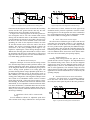
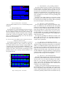
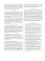
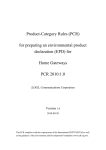
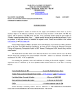
Troubleshooting and Fixing of Inverter Driven Induction Motor Bearing Currents in Existing Plants of
Large Size - an Evaluation of Possible Mitigation
Techniques in Practical Applications
1
S. Guttowski1, S. Weber1, M. Schinkel1, W. John1, H. Reichl2
Fraunhofer Institute for Reliability and Microintegration, Gustav-Meyer-Allee 25, 13355 Berlin, Germany
2
Berlin Center of Advanced Packaging, TIB4/2-1 Gustav-Meyer-Allee 25, 13355 Berlin, Germany
Abstract – The effect of bearing currents in inverter driven induction motors has been investigated and reported for about ten
years. Mitigation techniques have been developed and approved
by experiments. In this paper, the special situation of troubleshooting in a given configuration such as existing large plants is
discussed. The determination of the actual bearing current phenomenon and the development of the appropriate mitigation
technique under given circumstances are shown. A new equivalent circuit diagram for the bearing currents in large drives has
been developed and used for evaluation of mitigation techniques.
Experiences applying the mitigation techniques to a drive suffering premature damages due to rotor ground bearing current are
presented and discussed using experimental results.
I.
INTRODUCTION
The application of adjustable speed drives (ASD) is increasing due to improved system efficiencies providing energy savings and ease in control. The development of advanced power electronic switching devices has enabled high
frequency switching operation and has improved the performance of the pulse-width modulated (PWM) inverters of the
ASD. However, the high rate of voltage rise of typical IGBT
inverters has adverse effects in the form of motor insulation
stress, electromagnetic interference and bearing and leakage
currents caused by common mode voltages [1-6].
A high percentage of process disruptions are due to bearing
failures. In the meantime a substantial number of mitigation
techniques have been developed [1, 7-12]. However, the industrial user searching the literature for an immediate solution
encountering a concrete bearing current problem in an existing plant configuration finds itself abandoned since most of
the mitigation techniques are not feasible without enormous
changes of the electrical plant configuration. This paper addresses the practical problems being told to solve a bearing
current problem in an existing plant with premature bearing
failures due to rotor ground currents in large adjustable speed
drives.
The final conclusions derived from the mitigation method
evaluation can be summarized to a guideline that supports the
expert responsible for the bearing current suppression in existing plant configurations as well as during system modernizations.
II. BEARING CURRENT TROUBLESHOOTING
Troubleshooting in existing plants of large size means
firstly to determine which bearing current phenomena causes
the bearing failures. Therefore, a short review of the known
bearing current phenomena followed by a discussion how the
actual phenomenon can be determined will be given here.
A. Short Review of Bearing Currents Phenomena
The different types of bearings currents have been described very well by the authors in [8]. So, at this place only a
short review focusing on the specific aspects necessary for
this paper will be given. The common mode voltage caused
by the feeding inverter leads to currents due to the unavoidable parasitic capacities within the induction motor. In Figure 1 the allocation of these parasitic capacities within an
induction motor model can be seen. Four types of bearing
currents, the small capacitive currents, the electrostatic dis-
Figure 1: Parasitic capacities within of an induction motor
Figure 4: Equivalent circuit diagram for rotor ground currents
charge currents (EDM), the circulating bearing currents and
the rotor ground currents, have been explored so far. In this
paper the focus lies on high power applications, so not only
the small capacitive currents but also the electrostatic discharge currents (EDM) can be neglected.
Circulating bearing currents are known to be caused by the
high frequency current flowing from the stator to ground. As
shown in Figure 2, this current excites a circular magnetic
flux Φcirc, which induces an additional shaft voltage, thus
causing circular bearing currents.
Rotor ground currents are caused by poor grounding conditions that can be found especially in existing plants with older
electrical systems. In such configurations, the rotor ground
impedance may be significant lower than the grounding of the
stator housing. The unavoidable common mode current, generated by the high dv/dt of the common mode voltage, flows
to substantial portion through the bearings of motor via the
rotor and the driven machine to ground.
In Figure 3 the current paths of the rotor ground current
can be seen whereas the rectangle solid on the right side in the
figure shall mention the driven machine where the current is
flowing through. In Figure 4 an extension of the commonly
used equivalent circuit diagram for the bearing current phenomena is shown. Especially for the troubleshooting and
mitigation evaluation described in this paper this extension
has proofed to be very useful. In addition to the commonly
used equivalent circuit diagram in this single-phase diagram
the whole system has been taken into account. The power
converter is represented by the common mode voltage source
Vcm. The cable between the power converter and the motor
has been included by the elements Rc, Lc and Ccg. The elements Rw and Lw represent the winding of the induction motor. The capacities Cwf, Cwr, Crf, Cb1 and Cb2 are the parasitic
capacities within the motor as shown in Figure 1. In order to
discuss the phenomenon rotor ground current the diagram has
been extended by the impedances Zg,im and Zg,pm as well as
the capacity Cb,pm. The impedance Zg,im, which is the impedance of the real current path from the induction motor to the
ground, is the cause of current flowing through the bearings
to the driven machine. The capacity Cb,pm and the impedance
Zg,pm represent the currents path through the bearings of the
driven machine to ground.
In this diagram the two parallel paths of the common mode
current from the motor frame to ground can be seen and the
influence of the mitigation measures on these paths can be
evaluated. The measures against the rotor ground currents
have in common that the current path through the bearings of
the motor and the driven machine needs to be made more
unalluring so the dangerous current flows somewhere else.
Figure 3: Current paths of the rotor ground currents
B. Measurements for Phenomena Determination
The procedure necessary to determine the kind and exact
amount of current flowing through the bearings of an induction motor has been described based on the results of several
research projects. Although the methods applicable to the
machines especially dissected for the experiments can not be
applied to the motor of the large adjustable speed drives in an
existing plant being told to solve the bearing current problems. Knowing that the small capacitive currents and the
electrostatic discharge currents do not appear in large induc-
-U
+W
Φcirc
+V
-V
-W
+U
Figure 2: Causes and paths for circulating bearing currents
Figure 5: Investigation of rotor ground currents in existing plants
tion motors the investigation can be focused on the circulating
currents and the rotor ground currents. But only the rotor
ground currents can be measured in existing systems.
In Figure 5 the measuring points for the rotor ground current investigation can be seen. The common mode current
flowing into the induction motor is determined at measuring
point M1 indicates the amount of current that is flowing out of
the motor at the other current terminals such as the motor
grounding, the cable for the temperature monitor, the cable
for the shaft encoder and of course the shaft to the driven
machine. The current at measuring point M2 evaluates the
effectiveness of the motor grounding which might be very
helpful for explaining the current flowing through the shaft.
Whereas the measuring points M1 and M2 are easily to realize
the measuring point M3 can be realized only by using special
Rogowski-Coil current probes since the measurements have
to be taken during operation of the motor.
III. MITIGATION TECHNIQUES
Mitigation techniques for inverter driven bearing currents
have been developed and presented by different authors. The
question, underlying in this paper, focuses on the feasibility
of the mitigation methods for troubleshooting being told to
solve a bearing current problem in an existing plant with
premature bearing failures in large adjustable speed drives. So
the mitigation techniques need to be discussed in terms of
their suitability for a concrete bearing current problem in an
existing plant configuration. The mitigation techniques taken
into account are A) Modulation scheme with low common
mode voltage, B) dv/dt – Filter at the inverter output, C) Insulated bearings, D) Insulated clutch between induction motor
and machine, E) Low impedance connection between induction motor and machine, F) Shielded cables between inverter
and induction motor and G) Shaft grounding brush. The possibility of low resistance lubrication has been left out due to
the lacking availability.
A. Modulation scheme with low common mode
voltage
Several modulation schemes for adjustable speed drives
with common mode voltage reduction have been presented.
Figure 6: Equivalent circuit diagram for insulated bearings
The effectiveness of those schemes has been approved by
simulations and be practical experiments. From the troubleshooting point of view this approach can not be considered to
be a useful mitigation since the idea of changing the modulation scheme within an existing plant is not feasible.
B. dv/dt – Filter at the inverter output
The effectiveness of different types of filters at the inverter
output has been investigated carefully in [10]. Although filters that reduce the dv/dt of the line-to-earth voltage reduce
the rotor ground currents significantly the additional integration of such filters often exceed the possibilities during troubleshooting and fixing. Furthermore in many applications the
costs for additional filters between the motor and the induction motor can not be beard by the operating company.
C. Insulated Bearings
Insulating both bearings breaks the path for the rotor
ground currents as shown in Figure 6. The implementation of
one insulated bearing seems often to be the first mitigation
applied to the motor since the damaged bearing needs to be
changed anyway. However, this method may not be acceptable for some applications, since the shaft voltage still exists
and will attempt to find a path to ground elsewhere. In many
applications an electrical insulated rotor is not desired by the
operating company.
D. Insulated clutch between motor and machine
In Figure 7 the effectiveness of an insulating clutch between the motor and the driven machine is demonstrated.
Obviously the clutch opens the path for the rotor ground cur-
Figure 7: Equivalent circuit diagram for insulated clutch
Figure 8: Equivalent circuit for connection between motor and machine
rents and the currents on the shaft can be avoided. But the
integration of an insulating clutch into an existing system
means significant changes not only of the electrical but also
of the mechanical system parameter and is not acceptable for
operating companies.
E. Low impedance connection between induction
motor and machine
Being encountered by a rotor ground current problem to be
solved the electrical connection between the induction motor
and the machine seems to be very promising. As it can be
seen in Figure 8 the additional path between the motor frame
and the driven machine housing lays in parallel to the current
path though the bearings and the shaft. This mitigation can be
applied very easily and it leads to substantial improvements
as long as the connection does not exceed a certain length. In
several applications where other mitigations were eliminated
the bearing currents could have been reduced by factor 2. The
main disadvantage lies in the fact that the connection has to
be maintained.
F. Shielded cables between inverter and induction
motor
The length of the connection between the inverter and the
motor has an immense impact on the risk of bearing currents.
The use of shielded cables is known to reduce the rotor
ground currents as well as the circulating currents [7, 8, 13].
However, the higher cost due to the shielded cables always
needs to be motivated, and furthermore, shielded cables are
not feasible in all applications. In Figure 9 the equivalent
circuit diagram extended by the elements of the shield is
shown. It has been assumed that the shield has been contacted
on both the motor frame as well as the grounding point of the
Figure 9: Shielded Cables as mitigation for rotor ground currents
Figure 10: Shielded Cables as mitigation for rotor ground currents
power converter. In order to discuss the kind of shield necessary for this mitigation the equivalent circuit has been enhanced to the model shown in Figure 10. The effectiveness of
the shielded cable depends only on the magnetic coupling
between the inner conductors and the shield. Due to the low
frequencies that need to be handled here the use of the very
Figure 11: Cable configurations for bearing current mitigation
expensive EMC cable shields is not necessary.
In Figure 11 the cable configurations investigated using the
model shown in Figure 10 can be seen. The EMC shield, not
illustrated here, has been compared to a configuration with an
concentrical ground conductor and the configuration on the
right side in Figure 11, the symmetrical cable. Using the finite
element method the magnetic coupling between the inner
conductors and the shield has been calculated and used for a
simplorer circuit simulation. The results, the shield current Ish
relating to the common mode current Icm at the inner conductors are shown in Figure 12. It can bee seen that even with the
simplified model in Figure 10 the configuration with the con-
Figure 12: Shielding effectiveness of investigated cable
40
Common Mode Current
current [A]
-10
15
10
5
0
-5
-10
Shaft Current
current [A]
30
20
15
10
Ground Current
current [A]
10
0
5
0
-5
-10
0.0
10.0µ
20.0µ
30.0µ
40.0µ
50.0µ
60.0µ
time [s]
Figure 13: Bearing currents – initial situation
centrical ground conductor serves as a useful bearing current
mitigation.
G. Shaft grounding brush
The application of a shaft grounding brush inserts a bypass
for the currents in parallel to the bearings. But it is evident
that this mitigation would protect the motor bearings only
whereas the bearings in the driven machine suffer even higher
currents due to the lower impedance within the induction
motor. An additional disadvantage lies in the fact that the
brush needs to be maintained.
IV. EVALUATION OF THE MITIGATION TECHNIQUES BASED ON
A PRACTICAL APPLICATION
The mitigation techniques have been applied to a practical
bearing current problem in a drive system of a paper mill.
Two 500 kW induction motors driving a creping cylinder via
a common gear have been investigated comparatively. The
creping cylinder has the dimension of 5.5 x 5.95 meters and a
weight of 150 tones. In both motors the bearings have had
premature failures due to bearing currents identified to be
rotor ground currents.
40
current [A]
20
10
0
Shaft Current
4
current [A]
B. Approach 1 – improved grounding
The first approach aimed at improving grounding conditions. As mentioned in the introduction, the rotor ground
currents are caused mainly by poor grounding of the induction motors. In this example the induction motor is as usual in
paper mills arranged at a solid concrete block and no structural grounding such as machine frame was given. The improved grounding was provided by an additional flexible wire
from the motor to the grounding point of the building that is
much closer than 10 m.
The improved grounding has reduced the current at the
shaft at MP3 by about 20 %. So, the bearing currents have
shown peak values of up to 14 A, which still exceed the acceptable values significantly.
C. Approach 2 – low impedance connection
The mitigation described in section III.E was the second
approach to reduce the bearing currents that were measurable
at MP3. So an additional flexible cupper meshwork was connected between the induction motor and the frame of the
paper mill. In this particular case the shaft between the motor
and paper mill was fairly short, so this measure was successful. This additional wiring has reduced the remaining bearing
currents by factor 2, which basically confirms the experience
gained from other bearing current investigations.
Common Mode Current
30
2
0
-2
Ground Current
15
current [A]
A. Initial Situation – poor grounding conditions
The initial situation from the viewpoint of the bearing current phenomenon was characterized by a length of the cable
of 250 m and the concentrical shield of the cable was connected in such a way that the electrical conditions were corresponding to non-shielded cables. The grounding measure was
effective for currents of very low frequency since the length
of the grounding wire was about 10 m to the grounding point
of the building.
In Figure 13 the initial situation of the bearing current
problem has been recorded. Peak currents of up to 17 A could
be measured flowing through the bearings and the operating
time for the bearings was extremely shortened.
10
5
0
-5
0.0
10.0µ
20.0µ
30.0µ
40.0µ
50.0µ
time [s]
Figure 14: Bearing currents – final solution
60.0µ
D. Approach 3 – cable shield application
The cables in this particular paper mill were designed with
concentrical ground conductor but by mistake the connection
with the motor was not realized according to the requirements. So, it was possible to determine the influence of the
cable in a real system. Although the connection made subsequently did not reach the impedance that could had been
reached by correct installed wirings.
In Figure 14 the currents flowing into and out of this investigated induction motor are shown. Due to the special situation of subsequently connected shielding the common mode
current could be determined separately. In systems were the
concentrical grounding conductor has been installed correctly
the current probes can determine only the differential current
of the inner conductors and the shield. The current flowing
through the bearings and the shaft between the motor and the
paper mill could be reduced to about 2 A. According to the
experiences gained from other bearing current investigations
this is acceptable for induction motors of such size.
V. DISCUSSION
In this particular case the cable were prepared to electrically add the concentrical grounding conductor. So, it could
be shown to which extend this measure can reduce and as the
case may be avoid bearing current problems. But mostly, this
will not be the case. In existing systems such as paper mills
only the mitigations without any changes in the wiring harness will be acceptable.
Rotor ground currents occur often when the electrical drive
system in existing plants have been modernized. Depending
on the electrical system in the plant before the modernization
not the complete electrical systems is exchanged but for example only the power converter. Depending on the degree of
modernization the following guideline for bearing current
avoiding can be given.
A. Exchange of the complete drive system
In the case of a modernization of the whole system the safest way to avoid bearing current problems is to install cables
with concentrical grounding conductor. Although the grounding conditions at the places of the motors are expected to be
poor the only additional measure to be adopted is to connect
the motors with the grounding point of the building. The
additional costs due to the special cable are mostly acceptable
compared to the avoided risk of bearing damages.
B. Exchange of the power converters and wiring
If only the power converter and the wiring need to be exchanged basically the same recommendation can be given as
for A. But the connections of the concentrical cables at the
motor terminals need to be made very carefully since the
contact impedance is very important for the effectiveness of
the mitigation as shown.
C. Exchange of only the power converter
The real challenge for the system designer occurs when
only the power converters need to be changed and the wiring
and the motors have to remain. In this case mostly the cables
are not equipped with a shield and the other mitigations need
to be considered. The first step must be to improve the
grounding conditions of the induction motors. The low impedance connection between the motors and the frame of the
paper mill in combination with good grounding conditions
has solved many bearing current problems in the past. If these
mitigations do not solve the problem additional measures
such as output filters have to be considered. In either case the
rotor ground currents need to be checked for each motor of
the system if unexpected downtimes caused by premature
damages due to bearing currents shall be avoided.
VI. CONCLUSION
The idea of this paper is to provide the industrial user encountering a bearing current problem in an existing plant
configuration a guideline for the mitigation development
applicable for the industrial practice. For this reason, the
explored bearing current phenomena and the developed mitigation techniques have been reviewed. The mitigation techniques have been applied to a practical bearing current problem if a large drive. The effectiveness of the mitigation techniques has been determined by measurements. So, the appropriate mitigation technique for this specific bearing current
problem could be derived. The results of this investigation
have been derived from a bearing current problem of a concrete drive but, the cognitions are of general usefulness.
VII. REFERENCES
[1]
[2]
[3]
[4]
[5]
[6]
[7]
[8]
[9]
[10]
[11]
[12]
[13]
A. von Jouanne, H. Zhang, and A. K. Wallace, "An evaluation of
mitigation techniques for bearing currents, EMI and overvoltages in
ASD applications," Industry Applications, IEEE Transactions on, vol.
34, pp. 1113-1122, 1998.
S. Chen, T. A. Lipo, and D. W. Novotny, "Circulating type motor
bearing current in inverter drives," IEEE IAS Annual Meeting, 1996.
D. Busse, J. Erdman, R. J. Kerkman, D. Schlegel, and G. Skibinski,
"System electrical parameters and their effects on bearing currents,"
Applied Power Electronics Conference and Exposition. APEC 1996.
D. F. Busse, J. M. Erdman, R. J. Kerkman, D. W. Schlegel, and G. L.
Skibinski, "The effects of PWM voltage source inverters on the mechanical performance of rolling bearings," Industry Applications, IEEE
Transactions on, vol. 33, pp. 567-576, 1997.
S. Chen, T. A. Lipo, and D. Fitzgerald, "Modeling of motor bearing
currents in PWM inverter drives," Industry Applications, IEEE Transactions on, vol. 32, pp. 1365-1370, 1996.
J. Erdman, R. J. Kerkman, D. Schlegel, and G. Skibinski, "Effect of
PWM inverters on AC motor bearing currents and shaft voltages," Applied Power Electronics Conference and Exposition, APEC 1995.
P. J. Link, "Minimizing electric bearing currents in ASD systems,"
Industry Applications Magazine, IEEE, vol. 5, pp. 55-66, 1999.
A. Muetze and A. Binder, "Experimental evaluation of mitigation
techniques for bearing currents in inverter-supplied drive-systems - investigations on induction motors up to 500 kW," International Electric
Machines and Drives Conference, IEMDC 2003.
J. Zitzelsberger and W. Hofmann, "Effects of modified modulation
strategies on bearing currents and operational characteristics of AC induction machines," Industrial Electronics Society, 2004.
A. Muetze, A. Binder, H. Vogel, and J. Hering, "Experimental evaluation of the endangerment of ball bearings due to inverter-induced bearing currents," IEEE IAS Annual Meeting, 2004.
R. F. Schiferl and M. J. Melfi, "Bearing current remediation options,"
Industry Applications Magazine, IEEE, vol. 10, pp. 40-50, 2004.
D. Hyypio, "Mitigation of bearing electro-erosion of inverter-fed motors through passive common-mode voltage suppression," Industry Applications, IEEE Transactions on, vol. 41, pp. 576-583, 2005.
E. J. Bartolucci and B. H. Finke, "Cable design for PWM variablespeed AC drives," Industry Applications, IEEE Transactions on, vol.
37, pp. 415-422, 2001.