1
Paperless Recorder
B 70.6500.0
Operating Instructions
02.05/00378469
Contents
1
Introduction
7
1.1
Preface .......................................................................................................... 7
1.2 Arrangement of the documentation ........................................................... 8
1.2.1 Structure of these Operating Instructions ...................................................... 8
1.3
1.3.1
1.3.2
1.3.3
Typographical conventions ......................................................................... 9
Warning signs ................................................................................................. 9
Note signs ...................................................................................................... 9
Representation ............................................................................................. 10
2
Instrument description
2.1
Display and controls .................................................................................. 11
2.2
Operating principle and graphic elements .............................................. 12
2.3
Analog inputs .............................................................................................. 14
2.4
Event traces ................................................................................................ 15
2.5
2.5.1
2.5.2
2.5.3
Counters / Integrators / Timers ................................................................
Reporting periods of counts ........................................................................
Resetting the counters / integrators / timers ...............................................
Behavior on instrument reconfiguration .......................................................
2.6
Math / logic module ................................................................................... 20
2.7
Operating modes ........................................................................................ 23
2.8
Data storage ............................................................................................... 24
3
Operation and visualization
3.1
Basic menu ................................................................................................. 26
3.2
3.2.1
3.2.2
3.2.3
3.2.4
3.2.5
3.2.6
3.2.7
Visualization ................................................................................................
Diagram representation with digital display (small measurement) ...............
Diagram representation with scaling ............................................................
Diagram representation with bargraph .........................................................
Large digital display (large measurement) ....................................................
Curve representation (header switched off) .................................................
Evaluating the stored measurement data ....................................................
Counters / integrators / operating time ........................................................
3.3
Parameter setting ....................................................................................... 35
3.4
Configuration .............................................................................................. 38
11
16
18
18
19
25
27
28
29
29
30
30
31
34
Contents
3.5
Event list ...................................................................................................... 39
3.6
Disk manager .............................................................................................. 41
3.7
Instrument info ........................................................................................... 44
3.8
Text input ..................................................................................................... 46
3.9
Value input .................................................................................................. 47
3.10 Code number (password entry) ................................................................ 48
4
Configuration parameters
51
4.1
Operating example ..................................................................................... 51
4.2 Table of configuration parameters ...........................................................
4.2.1 Parameter setting .........................................................................................
4.2.2 Configuration - Instrument data ...................................................................
4.2.3 Configuration - Analog inputs ......................................................................
4.2.4 Configuration - Event traces ........................................................................
4.2.5 Configuration - Counter/Integrator (option) .................................................
4.2.6 Configuration - Measurement storage .........................................................
4.2.7 Configuration - Outputs (option) ..................................................................
4.2.8 Configuration - Operating functions .............................................................
4.2.9 Configuration - Texts ....................................................................................
4.2.10 Configuration - Interface .............................................................................
4.2.11 Configuration - Fine calibration ..................................................................
52
52
53
56
58
59
63
64
65
65
66
66
5
Setup program
69
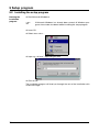
5.1
Hardware and software requirements ...................................................... 69
5.2
Installing the setup program ..................................................................... 70
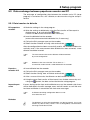
5.3 Data exchange between paperless recorder and PC ............................. 71
5.3.1 Data transfer via diskette ............................................................................. 71
5.3.2 Data transfer via setup interface .................................................................. 72
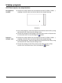
5.4
Math and logic module .............................................................................. 73
5.5
Character set .............................................................................................. 77
6
PC evaluation program
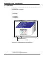
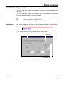
6.1
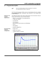
Program description .................................................................................. 79
79
Contents
7
Identifying the instrument version
81
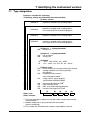
7.1
Type designation ........................................................................................ 81
7.2
Standard accessories ................................................................................ 82
7.3
Optional accessories ................................................................................. 82
8
Installation
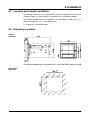
8.1
Location and climatic conditions .............................................................. 83
8.2
Mounting in position .................................................................................. 83
9
Electrical connection
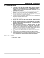
9.1
Installation notes ........................................................................................ 85
9.2
Technical data ............................................................................................. 85
9.3
Connection diagram .................................................................................. 86
10
TÜV Report on Data Manipulation Security
89
11
Index
93
83
85
Contents
1 Introduction
1.1 Preface
B
Please read these Operating Instructions before commissioning the instrument. Keep the operating instructions in a place which is accessible to all users at all times.
Please assist us to improve these operating instructions where necessary.
Your suggestions will appreciated.
Phone +49 661 6003-0
Fax
+49 661 6003-607
H
All necessary settings are described in this manual. If any difficulties should still arise during commissioning, you are asked not to
carry out any manipulations that could endanger your rights under
the instrument warranty!
Please contact the nearest subsidiary or the head office in such a
case.
E
When returning modules, assemblies or components, the regulations of EN 61340-5-1 and EN 61340-5-2 “Protection of electronic
devices from electrostatic phenomena” must be observed. Use
only the appropriate ESD packaging for transport.
Please note that we cannot accept any liability for damage caused
by ESD (electrostatic discharge).
7
1 Introduction
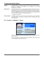
1.2 Arrangement of the documentation
The documentation for this instrument consists of the following parts:
Operating
Instructions
B 70.6500.0
These operating instructions are included in the delivery. They are addressed
to the equipment manufacturer (OEM), and to the user with appropriate technical expertise.
In addition to installation and electrical connection, they contain information
on commissioning, operation and parameter setting on the instrument, as well
as on the optional PC setup programm and the optional PC evaluation program (PCA).
Interface
Description
B 70.6500.2
It provides information on the serial interfaces (RS232 and RS485), which can
be supplied as an extra. Using the interface description, it is possible to develop specific programs which can, for instance, read out current measurement
data.
1.2.1 Structure of these Operating Instructions
These operating instructions are arranged in a way which permits the user to
enter directly into the operation and configuration of the instrument. Consequently, chapters dealing with items that normally arise only once are placed
at the end of the manual. These include instrument description, type designation, installation and electrical connection.
8
1 Introduction
1.3 Typographical conventions
1.3.1 Warning signs
The signs for Danger and Caution are used in this manual under the following
conditions:
V
A
E
Danger
This sign is used when there may be danger to personnel if the instructions
are disregarded or not followed accurately!
Caution
This sign is used when there may be damage to equipment or data if the instructions are disregarded or not followed accurately!
Caution
This sign is used where special care is required when handling electrostatically sensitive components.
1.3.2 Note signs
H
v
Note
This sign is used where your special attention is drawn to a remark.
Reference
This sign refers to further information in other handbooks, chapters or sections.
Footnote
abc1
Footnotes are notes which refer to certain points in the text.
Footnotes consist of two parts:
Marking in the text and the footnote text.
The marking in the text is arranged as continuous superscript numbers.
Action
h
This sign marks the description of a required action.
The individual steps are indicated by this asterisk, e. g.:
h key
Confirm with E
h Press the
h
9
1 Introduction
1.3.3 Representation
Keys
h+E
Keys are shown in a frame. Both symbols or text are possible. Where a key
has multiple functions, the text shown corresponds to the function which is
currently active.
Screen text
Program
manager
Texts displayed in the setup program are shown in italics.
Menu items
Edit !
Instrument data
10
Menu items of the setup program, which are referred to in this manual, are
shown in italics. Menu item and sub-menu item are each separated by “!”.
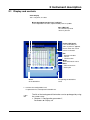
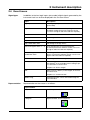
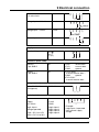
2 Instrument description
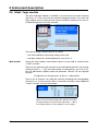
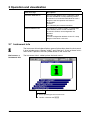
2.1 Display and controls
Color display
320 x 240 pixel, 27 colors
Menu-dependent function keys (softkeys)
screen-dependent function, represented by text or symbols
Status LED (red)
is on continuously while
an alarm is present
Power LED (green)
is on continuously as
soon as power is applied;
flashes when the screen
saver is activated.
Exit
- previous window
- cancel
current action
Menu
back to the basic menu1
Enter
- select menu item
- enter input
Cover
of the disk drive
for opening the disk drive
cover
1. not from the configuration level,
if a parameter has already been altered there.
H
The life of the background illumination can be prolonged by using
the screen saver.
v Chapter 4 “Configuration parameters”,
Parameters ! Display off
11
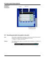
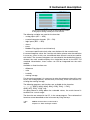
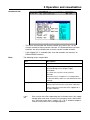
2 Instrument description
Opening and
closing the
housing door
Header
Status line
The housing door can
be opened or closed
by turning the knob
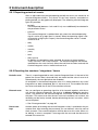
2.2 Operating principle and graphic elements
Keys
The recorder is operated from eight keys. Three of these have fixed functions,
the other five (softkeys) have menu-dependent functions.
v Chapter 2.1 “Display and controls”
Softkeys
12
The softkey functions appear in the bottom line of the display, as symbols or in
plain language.
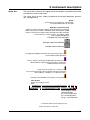
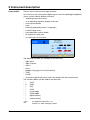
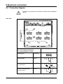
2 Instrument description
Status line
The status line is shown in the upper part of the display. It provides information
on important actions and states.
The status line is always visible, irrespective of the level (operation, parameters, configuration).
Alarm
If an alarm has occured (e. g. out-of-limit),
the (alarm) bell flashes in this field
Diskette / internal memory
Indicates the free storage capacity of the diskette or the internal
memory in percent. If there is a diskette error, the diskette symbol
flashes. The error message can be checked in the disk manager.
In the event of a “memory alarm”, the field is shown
with a yellow background.
vChapter 3.6 “Disk manager”
Storage capacity of diskette
available internal memory
The egg timer appears whenever the instrument is busy and
can therefore not be operated.
The “H” informs you that the indicated measurements are
derived from the past (history). The data saved in the
FLASH memory are shown.
In the event of an error, an “i” flashes here.
The cause of the error can be read out from the instrument
info window (v Chapter 3.7 “Instrument info”).
If the keys are inhibited, a key flashes in this position
Time & Date
shows the actual time and
date
Current diagram speed
Background color:
gray = normal operation,
blue = timed operation,
orange = event operation
Instrument name (16 characters max.)
shows last entry in event list
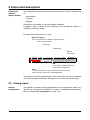
13
2 Instrument description
Channel line
(channel
representation)
The channel line shows the measurements of the active channels and their unit
as
- measurement
- scaling or
- bargraph.
Alternatively, the header can be switched off altogether.
In addition, alarms and out-of-limit conditions are made directly visible, according to the display mode.
Example: Measurement (meas. small)
Numerical display
The measurements are shown in numerical form.
Unit of measurement
Overrange
Underrange
State of
event traces
OFF
If a channel is switched off, then
there will be no indication.
Alarm
If an alarm is present (e. g. out-of-limit), the measurement
of the channel is shown on a red background.
The selection and visual presentation of the channel line can be controlled by
using the parameter Parameters ➔ Diagram view ➔ Channel representation.
2.3 Analog inputs
Internal
analog inputs
14
The paperless recorder can be equipped with 3 or 6 analog inputs. When configuring the analog inputs (Chapter 4.2 “Table of configuration parameters”),
these are designated analog input 1 — 3 (1 — 6).
2 Instrument description
2.4 Event traces
Signal types
In addition to the four logic inputs (extra code), digital signals generated by the
instrument itself can also be displayed in the six event traces:
Signal
Description
Logic input 1 — 4
Four logic inputs present in hardware
(extra code)
Logic channel 1 — 6
Channels which are created by using the math
and logic module (instrument software version
133.03.xx or higher and extra code are required)
Low alarm 1 — 6
Underlimit of channels
Low combination alarm
OR linkage of all low alarms
High alarm 1 — 6
Overlimit of channels
High combination alarm
OR linkage of all high alarms
Counter/integrator alarm 1 — 6
Limit infringements of counter/integrator
channels (instrument software version 133.03.xx
or higher and extra code are required)
Counter/integrator
combination alarm
OR linkage of all counter/integrator
alarms (instrument software version 133.03.xx or
higher and extra code are required)
Combination alarm
OR linkage of all low and high alarms
Memory alarm
Alarm is triggered when the residual capacity of
the diskette, or the available internal storage space, falls below a certain value.
Chapter 3.6 “Disk manager”
Error
Alarm when the battery is discharged, or the time
has to be reset.
Chapter 3.7 “Instrument info”
Modbus-Flag
Representation
Control flag which can be activated through the
serial interface.
Representation on the screen is as follows:
Representation
as symbol
On/Off represented as switch:
as diagram
Representation as time sequence:
15
2 Instrument description
Outputs
The digital signals can be used to operate the three relays (extra code). It is
possible to configure the action as n.c. (break) or n.o. (make)
(Configuration ➔ Outputs).
External texts
So-called “external texts” can be arranged through four logic inputs. Either a
standard text or one of the 18 definable texts can be used. The instrument automatically supplements the texts in order to distinguish between the appearance and disappearance of the signal. The external texts are configured on the
instrument under Configuration ➔ Operating functions.
v Chapter 3.5 “Event list”
Event operation
The digital signals can be used to activate event operation. In event operation,
the measurements are stored at a storage rate which is different from that in
normal operation.
2.5 Counters / Integrators / Timers
Counters, integrators and timers are available as extras from instrument software 133.03.xx.
These are not electrical measurement inputs (hardware), but channels which
are calculated by the recorder (software).
16
2 Instrument description
Counters
Counter inputs
- logic inputs
- logic channels
- alarms
- errors
- Modbus-Flag (signal via serial interface)
Counter
frequency
30Hz max.
Weighting
The count pulses can be evaluated (weighted). A down counter can be implemented by entering a negative weighting (e.g. weighting factor -1).
Each count change can be documented with an entry in the event list. The
new count is attached to the message.
Integrators
Integrator
inputs
- analog inputs 1— 3 (6)
Integrator
time base
- sec, min, hr and day
Weighting
You can also enter a weighting for the integrators.
Weighting
example
- flow measurement
- input signal from 0 — 20mA (corresponds to 0 — 1000 l/sec)
- time base 1sec
- weighting 0.001
- display of the integration value (quantity) in m³
Minimum size
of input signal
Entering a threshold value (amount of threshold value) has the effect that integration takes place only when the value has been exceeded. No integration
will occur on falling below the value. The advantage of integration with a
threshold value larger than 0 is that possible noise from a transducer can be
suppressed in this way.
Timers
The timer will count for as long as the selected logic input or one of the digital
signals is closed (set). The time can be displayed in sec, min, hr and days.
17
2 Instrument description
2.5.1 Reporting periods of counts
After an adjustable time period (reporting period) the counts are stored for all
counters/integrators/timers. The counts of the most recently concluded reporting period can be graphically displayed. The following counter/integrator
types are possible:
- periodic
The time period (between 1 min and 12 hrs) must additionally be selected in
the parameter Period.
- external
The counter/integrator is updated here only when the selected operating
signal is active (e.g. logic input is closed). When the operating signal is deactivated (e.g. logic input is open), the counter/integrator value is stored
and reset to 0.
- daily
- weekly
- monthly
- yearly
- total
- daily from-to
In addition, the period has to be selected, by means of the parameters
“Daily start time” and “Daily end time”. The counter/integrator will then be
updated from the start time only. When the end time has been reached, the
counter/integrator value is stored and reset to 0.
2.5.2 Resetting the counters / integrators / timers
Periodic reset
There is a reporting period for each counter/integrator/timer. At the end of this
period, the current data (value and time) are stored and the value is reset to 0.
Subsequently, the next period can be recorded.
An exception is the totalizer/integrator value. It is stored whenever any count/
integration has been completed, but it is not reset to 0. This enables the totalizer to be evaluated also in the PCA evaluation software.
External reset
You can configure an operating signal for all 6 channels together, with the result that the counters/integrators are reset to 0 without storing the previous
values. The period for the counter/integrator summation will be restarted at
this point. This means that after the test run of an installation, for instance, the
recording can be freshly started, thereby eliminating the test run values, which
are not required.
v See “Reset generation” on page 63.
Reset from
keys
18
Another option of resetting the counter/integrator values is provided at the parameter level. After entering the password, you can define a value for each of
the 6 channels. The counter/integrator will then be set to this value. When, after editing, a value is accepted, a message with the new and the old count is
entered in the event list.
2 Instrument description
The time period for the counter/integrator summation will not be freshly started. The previous counter/integrator values will also not be saved.
H
If you wish to save the previous counter/integrator values, you have to
execute the function “Update diskette incl. counters” in the Disk manager
menu before resetting.
In this way, you can restart the recording of individual counters/integrators, for
example, after the test run of an installation; the values of the test run, which
are not required, can thus be eliminated.
You can select a password other than that for accessing the configuration. The
password can be set under Configuration ➔ Instrument data ➔ Code
No.(Password) ➔ Counter/Int.reset.
Reset via
the “Disk
manager” menu
If the function Update diskette incl. counters is executed in the “Disk manager”
menu, the counts will also be stored and reset.
v See “Disk manager” on page 41.
2.5.3 Behavior on instrument reconfiguration
When the instrument is reconfigured, the current counter/integrator reporting
periods remain unaffected. The counter/integrator values will not be reset to 0
and the reporting period will not be restarted.
H
The values can be deliberately reset via the “Parameters” menu.
19
2 Instrument description
2.6 Math / logic module
The math and logic module is available as an extra from instrument software
133.03.xx. As is the case with the counters/integrators/timers, the math and
logic module, too, are channels that are not available in hardware, but are calculated through the instrument software.
The math and logic module consists of 2 parts:
- the math module for calculating analog values and
- the logic module for calculating boolean values (0 or 1).
Math module
Using the math module, measurement inputs can be used to calculate new
“virtual” channels.
There are no separate math channels for the calculated channels, the existing
analog channels 1 — 3 (6) are used instead. In configuration, you have to select the Mathematics option under the parameter “Sensor” for the required
channel.
Configuration ➔ Analog input x ➔ Sensor = Mathematics
Each of the 6 channels can either be used for recording the corresponding
channel, or as a math channel. With a 3-channel instrument, three additional
“virtual” channels can thus be created.
When the measurement inputs AE1 and AE2 are mathematically linked, the measurement inputs AE3 — AE5 in
the example above are not available as sensor inputs.
20
2 Instrument description
The channel number of a math channel indicates which
analog input is being used by the math channel.
The following variables are used for the formulae:
- analog inputs (AE1 — AE6)
- counter/integrator channels (ZI1 — ZI6)
- logic inputs (BE1 — BE4)
- alarms
- errors
- Modbus-Flag (signal via serial interface)
- instrument-specific data (only after consultation with the manufacturer)
If counter/integrator values are used for calculation, please note the reduction
in accuracy, since, in this case, two different data formats have to be used for
calculation. The counters/integrators are calculated in the double-float format,
whereas the math module employs the single-float format to the IEEE 754
standard. Nevertheless, these values can still be integrated into the math
module.
Available as fixed functions are:
- difference
- ratio
- humidity
- moving average
For the moving average, it is necessary to enter the reference channel (in most
cases, the analog input no.) and the time (in minutes), which are used for calculating the moving average.
The following operators and functions are available for the formulae:
+, -, *, /, (, ), SQRT(), MIN(), MAX(), SIN(), COS(), TAN(), **, EXP(),
ABS(), INT(), FRC(), LOG(), LN().
On going above or falling below the scaleable values, the math channel is
treated as for “out-of-range".
The formulae are entered in the PC, in the setup program. The mathematical
formulae cannot be edited on the instrument by using the keys.
H
Additional information can be found in
Chapter 5.4 “Math and logic module”
21
2 Instrument description
Logic module
There is also a maximum of 6 logic channels.
As is the case with all the other digital signals, the calculated digital (boolean)
values can be used for different functions:
-
recording in the event traces,
as an operating signal for display switch-off,
time synchronization,
timer,
externally operated counters / integrators,
counter/integr. reset,
event operation and key inhibit,
for output to a relay and
as count input for a counter.
The following variables are available for the formulae:
- logic inputs
- logic channels
- alarms
- errors
- Modbus-Flag (signal via serial interface)
- TRUE
- FALSE
- instrument-specific data (only after consultation with the manufacturer)
The functions below can be used for the formulae:
-
!
&
|
^
/
\
(
)
H
22
(NOT)
(AND)
(OR)
(XOR)
(rising edge)
(falling edge)
(open bracket)
(close bracket)
For additional information, see
Chapter 5.4 “Math and logic module”
2 Instrument description
2.7 Operating modes
3 operating
modes
The instrument has 3 operating modes:
- normal operation
- timed operation
- event operation
The following settings can, among others, be made for each of the three operating modes:
- stored value
- storage rate
Stored value
The stored value determines whether the average, minimum, maximum or instantaneous value of the time interval between two storage cycles or the peak
values (envelope) are stored. When “peak value” is set, then the minimum and
maximum values of the last storage cycle are stored.
Storage rate
The storage rate determines the time interval between two stored values. The
diagram speed corresponds to the storage rate, which means that at a storage
rate of 5sec, for example, the stored value is entered in the diagram every 5
sec.
Normal
operation
Normal operation is active whenever event or timed operation is not active.
Timed
operation
For timed operation, a period of time can be determined (24 hrs max.) within
which a specific stored value and a specific storage rate are active.
Event operation
Event operation is active as long as its operating signal (v Chapter 4.2.6
“Configuration - Measurement storage”) is active. Event operation can be
used, for example, to shorten the storage rate when an alarm is present.
Priority
The respective priorities of the operating modes are allocated as follows:
Active
operating
mode
Operating mode
Priority
Normal operation
low
Timed operation
average
Event operation
high
The active operating mode is indicated in the diagram by the background color for the diagram speed:
Operating mode
Color
Normal operation
gray
Timed operation
turquoise
Event operation
orange
v Chapter 2.2 “Operating principle and graphic elements”
23
2 Instrument description
2.8 Data storage
Recording
capacity
- internal memory: approx. 350,000 measurements
(with option: “Memory expansion to 2MB”: approx. 850,000
measurements)
- diskette: approx. 650,000 measurements
The recording capacity is reduced when many event messages are also
stored.
Storage rate
Different storage rates, ranging from 1sec to 32767sec, can be configured for
normal, event and timed operation under “configuration”.
The storage rate determines the time intervals at which the measurements are
stored.
Stored value
Under this parameter, the value to be stored (average, instantaneous, minimum, maximum or peak value) is configured separately for normal, event and
timed operation.
Recording
format
The data are recorded encoded in a proprietary format.
Recording
duration
The recording duration depends on various factors:
- number of analog channels and event traces being recorded
- storage rate
- number of events in the event list
H
Optimization
of recording
duration
The setup program calculates the recording duration for the current configuration.
The recording duration can be optimized by process-oriented selection of the
storage rate.
In normal operation (no fault, no alarm, ...), a storage interval as long as possible (e.g. 60sec, 180sec, …) should be selected, depending on the specific application.
In the event of an alarm or a fault, the storage rate can be shortened via event
operation, which ensures that the measurement data are recorded with a high
time resolution.
24
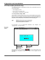
3 Operation and visualization
After starting up the paperless recorder by switching on the supply (power
ON), the start logo (company logo) appears.
During the screen build-up, the recorder is initialized with the data of the last
configuration.
H
After the initialization phase, the measurement diagram (visualization level) is displayed.
25
3 Operation and visualization
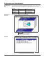
3.1 Basic menu
The basic menu is the central point from which the various levels of the instrument branch out.
The following levels are available:
- Visualization
- Parameters
- Configuration
- Event list
- Disk manager
- Instrument info
h Select the required level
h Confirm selection with E
The basic menu is displayed after pressing the Mkey1.
1. not from configuration level,
if a parameter has already been altered there.
26
3 Operation and visualization
3.2 Visualization
As has already been mentioned in Chapter 2.2 “Operating principle and graphic elements”, the softkeys can be found at the bottom of the screen. They
change their function according to the menu and are indicated as symbols or
in plain language.
Show event
list
Alter signal type
(representation)
- analog inp.
- analog & event
Evaluate stored measurement
data (history)
Alter channel representation (header)
- diagram representation with digital display (meas. small)
- diagram representation with scaling
- diagram representation with bargraph
- digital display large (meas. large)
- curve representation (header switched off)
Hide function keys (softkeys)
With instrument software version 133.03.xx (or higher), it is possible to equip
the recorder with “Counters/integrators” (extra code). In this case, the symbol
for indicating the counts will appear below the softkey on the right, the symbol
for showing the event list is shifted to the counter display.
Show counters / integrators / timers
27
3 Operation and visualization
3.2.1 Diagram representation with digital display (small measurement)
Diagram representation can be reached from the basic menu by calling up the
“visualization” menu, or by pressing the D key.
- Current measurements of the analog inputs including unit
- Measurement on red background ⇒ overlimit
Using the parameter Parameters ➔ Diagram view ➔ Signal type (or the
button), it is possible to select whether, in addition to the analog
channels, the event traces are also to be displayed. The contents of the header is determined by using the parameter Parameters ➔ Diagram
view ➔ Channel representation (or the
button).
28
3 Operation and visualization
3.2.2 Diagram representation with scaling
Scaling start of the selected channel
Lower limit marker of the selected channel
(no display when alarm is off)
Current measurement
Channel name
Upper limit marker
(no display when alarm
is off)
Scaling end
of the selected channel
The parameter Parameters ➔ Diagram view ➔ Channel indication is available
for selecting which scaling (on which channel) is the be indicated.
3.2.3 Diagram representation with bargraph
Scaling start of the selected channel
Lower limit marker of the selected channel
(no display when alarm is off)
Current measurement
Channel name
Upper limit marker
(no display when alarm
is off)
Scaling end
of the selected channel
Using the parameter Parameters ➔ Diagram view ➔ Channel indication, it is
possible to select which bargraph (on which channel) is to be indicated.
29
3 Operation and visualization
3.2.4 Large digital display (large measurement)
This display type is limited to the digital display.
3.2.5 Curve representation (header switched off)
This display type is limited to the representation of curves.
30
3 Operation and visualization
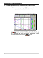
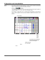
3.2.6 Evaluating the stored measurement data
History
The softkey function changes during evaluation and, additionally, the current
zoom factor and the cursor position (date and time) are displayed.
Scroll operation
Current zoom
(magnification)
Cursor (violet)
History activated
Date and time of measured
values at the cursor position
Measured value
at cursor position
Switch to
softkey functions
Zoom/Search
Scroll forwards fast
(one screen)
Scroll forwards slowly (one pixel line)
Scroll backwards slowly (one pixel line)
Scroll backwards fast (one screen)
Using these softkeys, the measurement data display can be scrolled (shifted)
on the screen within the measurement data that are stored in the internal
memory.
H
Measurement acquisition remains active during
history representation.
31
3 Operation and visualization
Zoom
If the zoom factor has to be adjusted, or specific times are to be searched for,
then it is necessary to switch the softkey functions.
h Press
softkey
The degree of compression of the measurement data on the screen is given as
a ratio in steps (1:1, 1:2, 1:5, 1:10, 1:20, 1:50 and 1:100).
For instance, 1:100 means that 1 screen pixel corresponds to 100 measurements, which signifies that only every hundreth stored measurement is displayed.
Cursor (violet)
Switch to
softkey
function
“Scroll”
Only for peak value acquisition:
Switch channel line between
min. and max. display
Position cursor on
time (selectable)
Zoom Zoom +
32
3 Operation and visualization
Positioning
the cursor
After pressing the key, the following dialog is available for positioning the cursor on a specific time:
After the date and time have been entered and the
pressed, the cursor is positioned on the selected time.
key has been
If no measurement data have been stored for the selected time, then the cursor is positioned on the next possible time.
Peak value
acquisition
If the data have been recorded in the “peak value” mode, then two different
measurements (one minimum and one maximum value) may be displayed
graphically for one instant of time (storage rate). Using the
key, it
is possible to switch between minimum and maximum value display within the
display mode “measurement”.
Function key
Channel line
Minimum
Maximum
Peak value acquisition is programmed (activated) by the parameters:
-
Configuration ➔ Measurement storage ➔ Normal display ➔ Stored value
-
Configuration ➔ Measurement storage ➔ Event operation ➔ Stored value
-
Configuration ➔ Measurement storage ➔ Timed operation ➔ Stored value
Further information on the “Measurement” display mode can be taken from
Chapter 3.2.1 “Diagram representation with digital display (small measurement)” and Chapter 3.2.4 “Large digital display (large measurement)”.
33
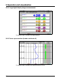
3 Operation and visualization
3.2.7 Counters / integrators / operating time
Count display is available from instrument software 133.03.xx (extra code). If
available, the screen below, for example, appears after pressing the softkey,
which shows the current counts in numerical form.
programmable
alarm limit
exceeded
overrange
expanded representation
show curves
Expanded representation is activated by pressing the softkey.
normal representation
current count
concluded reporting period
34
Event list
see
Chapter 3.5
“Event list”
3 Operation and visualization
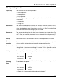
3.3 Parameter setting
The “Parameter” level is available to set
- contrast,
- speed indication,
- display off,
- diagram view and
- counter/integrator reset.
H
All
parameters are
or
selected using
and
the
and
keys.
Contrast
The contrast of the screen can be set here. This ensures that the screen is always legible, even under difficult light conditions.
Speed
indication
Here, “mm/h”, “time/div” or “storage rate” is selected for the speed display in
the diagram.
Example: A diagram speed of 1h/div corresponds to approx. 22mm/hr.
35
3 Operation and visualization
Display
off
Switch-off event = waiting time
For screen saving, a time between (0 and 32767min) can be set under the parameter “Waiting time”. If no recorder key is operated during this time, then the
screen goes dark. The power LED blinks during screen saving.
Screen saving (display off) is canceled by pressing any key on the recorder.
If 0min is set, then screen saving is deactivated.
Switch-off event = operating signal
In this case, screen saving is performed by using one logic input (extra code)
or a different operating signal. The logic input is selected via the “Operating
signal” parameter.
As long as the signal is present, the display remains off. No waiting time is
being taken into account.
Screen saving is deactivated when “Off” is selected.
H
Diagram
view
Only one type of screen saving can be active at a time.
Diagram view ➔ Signal type
Here, the representation mode of the measurement and event traces is determined:
- analog inputs
- analog inputs and event traces
Diagram view ➔ Channel representation
The contents of the channel bar is selected here:
- small measurement
- scaling
- bargraph
- large measurement
- switched off
Diagram view ➔ Channel display
The channels which are displayed in the channel line, in the representation
mode “Scaling” and “Bargraph”, are selected here.
Diagram view ➔ Paper perforations
Can only be selected if the analog channels only and no event traces are displayed. When yes is set, paper perforations appear in the diagram, thus giving
the picture the appearance of a conventional chart recorder.
36
3 Operation and visualization
Counter/
integrator
reset
After the password has been successfully entered, the counts for each of the 6
channels can be set to 0 or a defined value in this menu.
When a value has been input (confirm with E), a message with the new
and the old count is entered in the event list. The time period for the counter/
integrator summation will not be freshly started. The recent counter/integrator
values will also not be stored. If this is required, you have to execute the Update diskette incl. counter function in the Disk manager menu before resetting.
In this way, the recording of the counters/integrators can be restarted, for example, after the test run of an installation; the test run values, which are not required, can thus be eliminated.
You can set a password which is different from that for accessing the configuration. The default value is also 9200. The password can be set in the menu
Configuration ➔ Instrument data ➔ Code No. (Password) ➔ Counter/Int. reset.
37
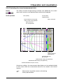
3 Operation and visualization
3.4 Configuration
On calling up the configuration level, the password is requested (factory-set:
9200). It also serves to prevent unauthorized alteration of the configuration.
v Chapter 3.9 “Code number (password entry)”
Window
technology
Like for the other levels, the principle of configuration is also based on menuled window technology. Individual menu items can be selected in the windows. The window title describes the contents of the window.
When a menu item has been selected, a further window is opened with new
menu items, until the required parameter is finally reached. If several windows
are open, the window title assists in orientation.
Window title
Current setting
Parameter can be selected/edited
Parameter is inhibited
The configuration of the paperless recorder is sub-divided into the following
levels:
v Chapter 4 “Configuration parameters”
38
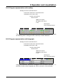
3 Operation and visualization
3.5 Event list
Events
Various events can initiate texts which are included in the event list and saved
in the internal memory or on diskette. Events may include:
- alarms triggered by out-of-limit conditions on individual channels,
- external texts triggered through logic inputs,
- system messages (e. g. power ON/OFF, summer/winter time changeover),
Event
definition
Foll all events, except for system messages, it is possible to configure whether
- the message text is to be included in the event list,
- the standard text internal to the instrument
- or one of the texts (see below) is used.
Text
assignment
The texts (standard texts or 18 freely definable texts) are assigned to the
events at the operating level “Configuration”
(v Chapter 4 “Configuration parameters”).
Freely definable
texts
18 texts can be freely defined, up to a length of 20 characters.
Standard texts
The instrument offers standard texts as listed in the following table:
Standard text
Note
Chanx low alarm ON
Chanx low alarm OFF
Chanx high alarm ON
Chanx high alarm OFF
Alarm counter/int. x ON
Alarm counter/int. x OFF
Logic input y ON
Logic input y OFF
Logic channel y ON
Logic channel y OFF
x = channel number
Counter x: y
x = counter channel number
y = input number
y = counter value (9 digits)
Power ON
Power OFF
Data lost
Summer time start
Summer time end
New configuration
Counter/int. x from y reset to z
x = counter/int. channel number
„Text 1 — 18“
18 freely definable texts
with 20 characters each
y = old counter/int. value (9 digits)
z = new counter/int. value (9 digits)
39
3 Operation and visualization
Supplementary
text
The instrument automatically supplements the texts by “ON” or “OFF”, to enable the distinction between appearance and disappearance of the signal.
Example:
Basic menu ➔
Event list
Standard text
Supplementary text Entry in event list
Logic input 2
ON
Logic input 2 ON
Logic input 2
OFF
Logic input 2 OFF
The event list is called up via the basic menu:
h Select operating level Event list
h Confirm selection with E
Event list
jump back directly into diagram presentation
40
3 Operation and visualization
3.6 Disk manager
Automatic
storage of
measurement
data
The data stored in the measurement data memory (FLASH) of the recorder are
saved at regular intervals to the diskette in the instrument. The evaluation program of the PC (v Chapter 6 “PC evaluation program”) reads the data from
the diskette and provides convenient functions for evaluation.
A
The stored data on the diskette and in the FLASH memory are deleted when the configuration is changed.
Loading and
saving the
configuration
data
The configuration data can be downloaded from and saved to diskette. A configuration can thus be copied from one instrument to another, or it can be
transferred from and to the PC setup program.
Basic menu ➔
Disk manager
The disk manager is called up via the basic menu.
h Select operating level Disk manager
h Confirm selection with E
The functions
- Update disk. incl. counter ...,
- Compl. meas. data ➔ Disk.,
- Config. data ➔ Diskette and
- Diskette ➔ Config. data
are protected against unauthorized access by a password (factory-set: 9200).
41
3 Operation and visualization
Disk manager
Measurement data not yet saved are written to diskette
Counter/intergrator reporting periods are concluded and
written to diskette, together with the measurement data not
yet saved. Counter/integrators are reset (to 0) and restarted.
All measurement data in the memory are written to diskette.
The configuration data are written to diskette
The configuration data are read in from diskette
Residual capacity of diskette in percent
Background flashes on error
e. g. “diskette full”, “no diskette”
Start action
Select action
H
Memory
alarm
The function “Compl. measurement data ➔ Disk.” serves to salvage data when the original diskette is no longer available.
At the configuration level, a percentage (residual capacity of diskette) can be
specified under Instrument data ➔ Memory alarm. When the residual capacity
of the inserted diskette reaches this percentage, the signal “Memory alarm” is
activated. It can, for instance, be used to operate a relay or to switch over to
event operation.
v Chapter 2.8 “Data storage”
Chapter 2.4 “Event traces”
Chapter 4 “Configuration parameters”
42
3 Operation and visualization
Status
messages
Status messages of the disk manager are displayed in the corresponding action window. The following status messages are possible:
Status message
Description
DISKETTE UPDATED
Directly before removing the diskette from the
instrument, it is necessary to call up Update
diskette, so that all the measurement data up to
the time of removal are contained on the diskette.
The data not yet saved since the last automatic
save are written to diskette.
DISKETTE NOT UPDATED
An error has occurred during updating.
This message may have several causes.
Remedy:
Repeat procedure
INITIALIZING DISKETTE
The instrument recognizes when new or foreign
diskettes are inserted.
A
New or foreign diskettes are
overwritten without a security check.
NO DISKETTE
If there is no diskette in the instrument, the
diskette symbol flashes in the status line.
DISKETTE
WRITEPROTECTED
The inserted diskette cannot be written to
because it is write protected.
Remedy:
Remove write protection.
DISKETTE FAULTY
An error has occured while writing to diskette.
The diskette is faulty.
Remedy:
Insert new (DOS-formatted) diskette.
DISKETTE FULL
If the diskette is full, the diskette symbol flashes in
the status line. No more data are written to
diskette.
Remedy:
Insert a blank diskette before the measurement
data memory of the recorder is also full. If this is
not done, then measurement data will be lost.
PROGRAM DISKETTE
This message appears when a program diskette is
inserted in the disk drive and measurement data
have to be written.
Remedy:
Insert the correct diskette, or a blank one.
CONFIG. DISKETTE
This message appears when a configuration diskette is inserted in the disk drive and measurement data have to be written.
Remedy:
Insert the correct diskette, or a blank one.
43
3 Operation and visualization
Status message
Description
GOLDCAP WAS EMPTY
This message appears when a capacitor is built
into the recorder for memory buffering and the
instrument has remained switched off for such a
long time that the capacitor has become
discharged.
Caution:
This will falsify the measurement data.
WRONG VERSION NO.!
An attempt was made to read in a configuration
from diskette, but the version numbers of
instrument software and configuration are
different.
Remedy:
Convert configuration diskette via the PC setup
program and create a new one.
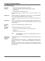
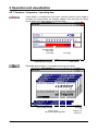
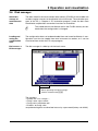
3.7 Instrument info
The instrument info window displays general information about the instrument.
It also includes errors “Battery empty” and “Data lost”. If one of these instrument errors is present, the info symbol flashes in the status line.
Basic menu ➔
Instrument info
The instrument info is called up from the basic menu:
h Select operating level Instrument info
h Confirm selection with E
44
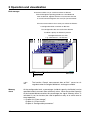
3 Operation and visualization
Instrument info
- This menu also includes the version number (e.g. 133.01.01), i.e. the
version number of the instrument software. It is important because some
functions are only available from a certain version number onwards.
- If the “Digital-I/O“ is available (Yes), then the recorder also contains an
RS232/RS485 interface.
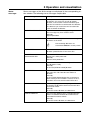
Error
The following errors are possible:
Error
Description
none
Instrument o.k.
Data lost
A discharge of the battery/storage capacitor
occured during the last lengthy supply
interruption.
The clock was set to 01.01.97 00:00:00.
Remedy:
Reset the time (v Chapter 4.2.2 “Configuration Instrument data”) and use a new diskette for data
storage.
Battery empty
This message appears on instruments with lithium
battery when the time was reset after a data loss.
Please return the instrument to the supplier for a
change of battery.
H
Data can be lost after separating the instrument from the supply
voltage after more than 10 years on instruments with a lithium battery, and after more than 2 weeks (15 — 25°C ambient temperature) on instruments with a storage capacitor.
45
3 Operation and visualization
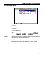
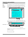
3.8 Text input
Input
options
The configurable texts can be input either through the setup program or directly on the instrument. This section describes the input on the instrument.
Character
selection
The display below is shown when a text (e. g. Configuration ➔ Texts) is selected at the configuration level for editing by using E.
Select the character to be altered using the softkeys
Switch to character set matrix
After the character to be altered has been selected and the switch made to
character set matrix, the cursor is positioned on the current character in the
character set matrix.
Character input
The softkeys change their function, as can be seen from the picture below:
Select new character
Enter character
After the entire text has been input, it can either be entered or all alterations
cancelled:
h Confirm text with E
or
h cancel text input with D
46
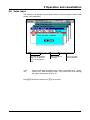
3 Operation and visualization
3.9 Value input
The softkeys can also be used to enter values on the instrument (shown here
during fine calibration).
Increase the selected
digit (+1) or decrease
(-1) it, or change the
sign
H
Select the digit to
be altered
Alter the number
of decimal places
The sign can only be altered if the value is not equal to “0”, which
means that, when entering values, you cannot start with altering
the sign if the present value is “0”.
Use E to confirm the entry or D to cancel it.
47
3 Operation and visualization
3.10 Code number (password entry)
The following functions are protected ex-factory from unauthorized access by
a password request:
- the Configuration menu
- parts of the Disk manager menu
- the Parameters ➔ Counter/Int. reset menu
The factory default setting is 9200.
A password can also be used to secure access to the recorder via the serial interface. In this case, however, the factory setting is 0 (no password request). If
you enter a value unequal to 0, please take into account that this number must
also be sent to the recorder by an attached communication program.
H
Additional information on password request
for the serial interface can be found in the
Interface Description B 70.6500.2.
All passwords can be programmed
“Configuration - Instrument data”).
differently
(see
Chapter
4.2.2
Password
request
Increment (+1) or
decrement (-1) the
selected digit
Select the digit to
be altered
After the entry has been completed (
), it can be confirmed by using
the E key. Using D, the password request will be stopped and the
menu left.
48
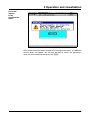
3 Operation and visualization
Password
request
in the
Configuration
menu
After the password has been entered in the Configuration menu, an additional
security query will appear. You will only be able to access the parameters
when you have confirmed the query with E.
49
3 Operation and visualization
50
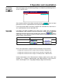
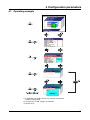
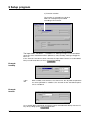
4 Configuration parameters
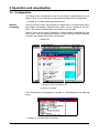
4.1 Operating example
1.) if applicable, the code number must also be entered here
(factory setting: 9200)
2.) cancel entry; the old settings are retained
3.) confirm entry
51
4 Configuration parameters
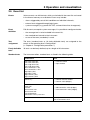
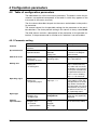
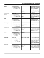
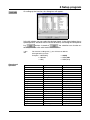
4.2 Table of configuration parameters
The table below lists all the instrument parameters. The order in which the parameters are explained corresponds to the order in which they appear on the
instrument (in the menu structure).
The first column describes the path via the menus and windows to the particular parameter.
The second column lists the possible settings for the parameter or the possible selections. The factory default setting in this column is always shown bold.
The third column contains a description of the parameter, or the possible selections, if the parameter and its function or its selection is not self-evident.
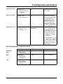
4.2.1 Parameter setting
Parameter
Value/selection
Description
Contrast
Parameters
➔ Contrast
0 — 16 — 31
Contrast of display
Speed indication
Parameters
➔ Speed indication
in mm/h,
Time/div,
Storage rate
The selected display mode
is shown in the diagram
representation
Switch-off event
Parameters
➔ Display off
➔ Switch-off event
Waiting time,
Operating signal
The type of display switchoff is selected here
Waiting time
Parameters
➔ Display off
➔ Waiting time
0 — 32767min
Time after which the display is switched off. Any
key stroke will re-activate
the display. The parameter
can only be entered when
the parameter Switch-off
event is set on “Waiting
time”. 0 = no switch-off
Operating signal
Parameters
➔ Display off
➔ Operating signal
Off,
Logic inp1 — 4
If one of the 4 logic inputs
(extra code) is set to “off”
and operated, then the display will be switched off.
The parameter can only be
entered when the parameter Switch-off event is set
on “Operating signal”.
Signal type
Parameters
➔ Diagram view
➔ Signal type
Analog input
Analog&Event
Determines which measurements are graphically
displayed
Channel
representation
Parameters
➔ Diagram view
➔ Channel
representation
Meas. small,
Scaling,
Bargraph,
Meas. large,
Off
Determines the contents of
the channel line (header)
52
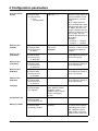
4 Configuration parameters
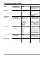
Channel indication
Parameters
➔ Diagram view
➔ Channel indication
➔ Analog
input 1 — 6
Yes,
No
“Yes” means that the selected channels are shown
in the header
Paper perforations
Parameters
➔ Diagram view
➔ Paper perforations
No,
Yes
“Yes” means that paper
perforations are shown
within the graphic display,
on the left and right
margins of the screen.
Paper perforations can
only be activated and
shown if no event traces
have been selected (signal
type = analog input).
Counter/Int. reset
Parameters
➔ Counter/Int. reset
➔ Channel 1 — 6
-999999999 — 0 —
+999999999
The start value for the
counter or integrator can
be entered here. The
current value is not saved.
Count changes are documented in the event list.
v Chapter 3.3 “Parameter setting”
If password request is active, (password “Counter/
Int. reset” > 0), the start values can only be set if the
password has been entered correctly.
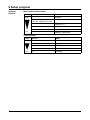
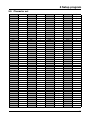
4.2.2 Configuration - Instrument data
Parameter
Value/selection
Description
Instrument
name
Configuration
➔ Instrument data
➔ Instrument name
16 characters
v Chapter 3.8 “Text input”
Date
Configuration
➔ Instrument data
➔ Date and time
➔ Date
any data
Input of current date
Time
Configuration
➔ Instrument data
➔ Date and time
➔ Time
any time
Input of current time
53
4 Configuration parameters
Synchronization
of time
Configuration
➔ Instrument data
➔ Date and time
➔ Time
synchronization
Off,
Logic inp1 — 4
Using this parameter (function), the system clocks of
several recorders can be
simultaneously synchronized.
When a logic input has
been selected and is operated (transition from “Low
to ”High”), then the time
can be synchronized. The
seconds are decisive in the
time change. They are
used for rounding the time
up or down.
Example:
12:55:29 -> 12:55:00
12:55:30 -> 12:56:00
Summer time
(switch)
Configuration
➔ Instrument data
➔ Summer time
➔ Switch
Off,
User timed,
Automatic
Automatic:
2:00 hrs or 3:00 hrs on the
last Sunday in March or
October
Summer time
(start date)
Configuration
➔ Instrument data
➔ Summer time
➔ Start date
any date
can only be configured if
the changeover (switch) is
set to “User timed”
Summer time
(start time)
Configuration
➔ Instrument data
➔ Summer time
➔ Start time
any time
can only be configured if
the changeover (switch) is
set to “User timed”
Summer time
(end date)
Configuration
➔ Instrument data
➔ Summer time
➔ End date
any date
can only be configured if
the changeover (switch) is
set to “User timed”
Summer time
(end time)
Configuration
➔ Instrument data
➔ Summer time
➔ End time
any time
can only be configured if
the changeover (switch) is
set to “User timed”
Language
Configuration
➔ Instrument data
➔ Language
German, English, French,
Dutch, Spanish, Italian,
Hungarian, Czech,
Swedish, Polish, Danish,
Finnish, Portuguese,
Russian
Temperature unit
Configuration
➔ Instrument data
➔ Temperature unit
°C, °F
Memory readout
Configuration
➔ Instrument data
➔ Memory readout
with diskette,
via RSxxx
54
Determine here how data
are mainly to be read out.
Depending on the selection, a different value is
made visible via the free
capacity in the status line.
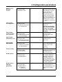
4 Configuration parameters
Memory alarm
(diskette
reserve)
Configuration
➔ Instrument data
➔ Memory alarm
1 — 10 — 100%
Code number
of configuration
0000 — 9200 — 9999
Configuration
➔ Instrument data
➔ Code No. (password)
➔ Configuration
Code number for
configuration level;
0000 = off
The data saved on diskette and in the FLASH
memory are deleted
when the configuration is
changed.
Code number
of disk manager
(Disk Code No.)
0000 — 9200 — 9999
Configuration
➔ Instrument data
➔ Code No. (password)
➔ Disk manager
Code number for
functions in the
“File manager” menu;
0000 = off
Code number
Counter/Int. reset
0000 — 9200 — 9999
Configuration
➔ Instrument data
➔ Code No. (password)
➔ Counter/Int. reset
Code number to delete the
individual counts;
0000 = off
Code number
RS232/RS485
0000 — 9999
Configuration
➔ Instrument data
➔ Code No. (password)
➔ RS232/RS485
Code number to protect
from unauthorized access
to data via the serial
interface;
0000 = off
Factory setting
Configuration
➔ Instrument data
➔ Enter defaults
Yes = enter factory default
setting (when entered, the
parameter returns
automatically to No)
Enable options
Configuration
➔ Instrument data
➔ Enable options
Enable options
Code No.
determined
Configuration
➔ Instrument data
➔ Enable options
➔ Code No.
determined
No, Yes
The signal is activated
when the residual capacity
of the diskette, or of the
internal memory, has
fallen to this value.
The parameter Memory
readout can be used to
determine whether the
alarm was initiated by the
diskette or the memory.
v Chapter 2.4 “Event traces”
The parameter is available
for enabling additional
functions, such as the
math/logic module or
counter/integrator. The
parameter is not available
if all recorder functions
have been enabled.
(display of Code No.)
The manufacturer has to
be informed about the
value displayed here and
will issue the enabling
code.
55
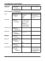
4 Configuration parameters
Enter enabling code
Enter the enabling code
you have received here.
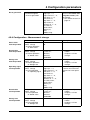
Parameter
Value/selection
Description
Sensor
Configuration
➔ Analog inputs
➔ Analog input 1—6
➔ Sensor
Off,
Res. therm.,
Thermocouple,
Current,
Voltage,
Math
Depending on the selected sensor, only the relevant
parameters can be
selected for configuring the
analog input.
Linearization
Configuration
➔Analog inputs
➔ Analog input 1—6
➔ Linearization
Linear, Pt100, Pt100 JIS,
Ni100, Pt500, Pt1000,
Pt50, Cu50, Fe-Con J,
NiCrCon E, Ni-CrNi K,
NiCrSi N, Cu-Con T,
PtRhPtRh B,
PtRh-Pt R, PtRh-Pt S,
Cu-Con U, Fe-Con L,
W3W25Re, W5W26Re
Connection circuit
2 — 4 wire
Configuration
➔Analog inputs
➔ Analog input 1—6
➔ Connection circuit
Cold junction
Configuration
➔Analog inputs
➔ Analog input 1—6
➔ Cold junction
Internal Pt100,
External const
External CJ
temperature
Configuration
➔ Analog inputs
➔ Analog input 1—6
➔ Ext. CJ temp.
-50 to +150°C
Range start
Configuration
➔Analog inputs
➔ Analog input 1—6
➔ Range start
any value
Enable options
Enabling code
Configuration
➔ Instrument data
➔ Enable options
➔ Enabling code
4.2.3 Configuration - Analog inputs
External cold junction temperature for thermocouples
0mA
Range end
Start temperature
56
Configuration
➔Analog inputs
➔ Analog input 1—6
➔ Range end
any value
Configuration
➔ Analog inputs
➔ Analog input 1—6
➔ Start
temperature
any value
20mA
Only for sensor types:
current, voltage with linearization for resistance thermometer, thermocouple.
Only for signals which are
not yet linearized.
4 Configuration parameters
Parameter
Value/selection
Description
End temperature
Configuration
➔Analog inputs
➔ Analog input 1—6
➔ End
temperature
any value
Only for sensor types:
current, voltage with linearization for resistance thermometer, thermocouple.
Only for signals which are
not yet linearized.
Scaling start
Configuration
➔ Analog inputs
➔ Analog input 1—6
➔ Scaling start
-99999 to 0 to +99999
Scaling end
Configuration
➔Analog inputs
➔ Analog input 1—6
➔ Scaling end
-99999 to +100 to +99999
Filter constant
Configuration
➔Analog inputs
➔ Analog input 1—6
➔ Filter constant
0.0 to 0.1 to 10.0s
Channel name
Configuration
➔Analog inputs
➔ Analog input 1—6
➔ Channel
name
7 characters
Inp. 1
Short designation. It is
shown in the channel line
(header) with bargraph and
scaling.
v Chapter 3.8 “Text input”
Unit
Configuration
➔ Analog inputs
➔ Analog input 1—6
➔ Unit
5 characters
v Chapter 3.8 “Text input”
Decimal place
Configuration
➔ Analog inputs
➔ Analog input 1—6
➔ Decimal place
Automatic,
X.XXXX, XX.XXX,
XXX.XX, XXXX.X,
XXXXX.
Automatic: representation
with max. resolution
Line width
Configuration
➔ Analog inputs
➔ Analog input 1—6
➔ Line width
Thin,
Thick
Line width of the measurement curve within the
graphical display
Alarm
Configuration
➔Analog inputs
➔ Analog input 1—6
➔ Alarm
➔ Alarm
Off,
Activated
Low limit
Configuration
➔Analog inputs
➔ Analog input 1—6
➔ Alarm
➔ Low limit
-99999 to 0 to +99999
High limit
Configuration
➔Analog inputs
➔ Analog input 1—6
➔ Alarm
➔ High limit
-99999 to 0 to +99999
%
57
4 Configuration parameters
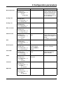
Differential
Parameter
Value/selection
Configuration
➔Analog inputs
➔ Analog input 1—6
➔ Alarm
➔ Differential
-99999 to 0 to +99999
Description
(1) = Low limit
(2) = High limit
(3) = Differential
v Chapter 3.5 “Event list”
Configuration
➔Analog inputs
➔ Analog input 1—6
➔ Alarm
➔ Text
low alarm
Standard text,
Text 1 — 18,
No text
Text high alarm
Configuration
➔ Analog inputs
➔ Analog input 1—6
➔ Alarm
➔ Text
high alarm
Standard text,
Text 1 — 18,
No text
Alarm delay
Configuration
➔Analog inputs
➔ Analog input 1—6
➔ Alarm
➔ Alarm
delay
0 — 32767s
Alarm delay is activated at
a value of > 0.
When activated, an alarm
will only be generated
when it has been present
for at least as long as it
takes for the set time to
elapse.
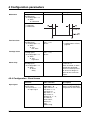
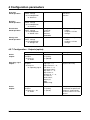
Parameter
Value/selection
Description
Configuration
➔ Event traces
➔ Event traces 1 — 4
➔ Input signal
Off,
Logic inp1 — 4,
Logic channel 1 — 6,
Low alarm 1 — 6,
Low comb. al.,
High alarm 1 — 6,
High comb. al.,
Counter/I al. 1 — 6,
C/I comb. al.,
Comb. alarm,
Memory al.,
Error,
Modbus-Flag
The event (digital signal)
which is to be recorded is
assigned to an event trace.
Text low alarm
v Configuration ➔ Texts,
page 65
4.2.4 Configuration - Event traces
Input signal
58
4 Configuration parameters
v Chapter 3.8 “Text input”
Configuration
➔ Event traces
➔ Event traces 1 — 4
➔ Trace designation
7 characters
Input signal
Configuration
➔ Event traces
➔ Event traces 5 — 6
➔ Input signal
Off,
Logic inp1 — 4,
Logic channel 1 — 6,
Low alarm 1 — 6,
Low comb. al.,
High alarm 1 — 6,
High comb. al.,
Counter/I al. 1 — 6,
C/I comb. al.,
Comb. alarm,
Memory al.,
Error,
Modbus-Flag
The event (digital signal)
which is to be recorded is
assigned to an event trace
Trace designation
Configuration
➔ Event traces
➔ Event traces 5 — 6
➔ Trace designation
7 characters
v Chapter 3.8 “Text input”
Trace designation
BE 1 —4
xxxx
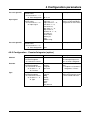
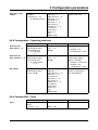
4.2.5 Configuration - Counter/Integrator (option)
Parameter
Value/selection
Description
Channel
Configuration
➔ Counter/Integrator
➔ Counter/In. channs.
1—6
Select channel for which
the subsequent parameters are to be configured.
Function
Configuration
➔ Counter/Integrator
➔ Counter/Int. channs.
➔ Channel 1 — 6
➔ Function
Off,
Counter,
Integrator,
Oper. time
Select the desired function
here.
v Chapter 2.5 “Counters /
Integrators / Timers”
Type
Configuration
➔ Counter/Integrator
➔ Counter/In. channs.
➔ Channel 1 — 6
➔ Type
Periodic,
External,
Daily,
Weekly,
Monthly,
Yearly,
Total,
Daily from-to
Reporting period.
Select here when the count
is to be stored and reset.
59
4 Configuration parameters
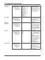
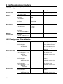
Input signal
Configuration
➔ Counter/Integrator
➔ Count/In. channs.
➔ Channel 1 — 6
➔ Input signal
Off,
Logic inp1 — 4,
Logic channel 1 — 6,
Low alarm 1 — 6,
Low comb. al.,
High alarm 1 — 6,
High comb. al.,
Counter/I al. 1 — 6,
C/I comb. al.,
Comb. alarm,
Memory al.,
Error,
Modbus-Flag
The parameter is only
programmable when
“Counter” or “Operating
time” has been selected
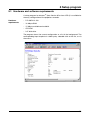
under Function.
Please select which event
is to be counted.
Input signal
Configuration
➔ Counter/Integrator
➔ Counter/In. channs.
➔ Channel 1 — 6
➔ Input signal
Analog inp1 — 3 (6)
The parameter is only programmable when “Integrator” has been selected
under Function.
Select which input is to be
integrated.
Weighting
(evaluation)
Configuration
➔ Counter/Integrator
➔ Counter/Int. channs.
➔ Channel 1 — 6
➔ Weighting
-99999 to +1 to +99999
Select the weighting factor
here.
If, for instance, 0.001 is entered, a conversion from
l/sec to m³/sec can be
achieved. If a negative
weighting factor is entered
(e.g. -1), the counter will
count down.
Time base
Configuration
➔ Counter/Integrator
➔ Counter/In. channs.
➔ Channel 1 — 6
➔ Time base
Second,
Minute,
Hour,
Day
The parameter is only programmable when “Integrator” or “Operating time”
has been selected under
Function.
Integrator:
Select the time base for integrating the selected
channel (e.g. second when
your sensor generates a
signal in liters/sec).
Operating time:
Select the unit used for
counting the time.
Threshold value
Configuration
➔ Counter/Integrator
➔ Counter/In. channs.
➔ Channel 1 — 6
➔ Threshold
value
0 — 99999
The parameter is only programmable when “Integrator” has been selected under Function.
Enter the threshold value
which has to be exceeded
for integration.
60
4 Configuration parameters
Channel name
(line 1)
Configuration
➔ Counter/Integrator
➔ Counter/In. channs.
➔ Channel 1 — 6
➔ Channel name
7 characters
Counter/
The text that has been
entered appears together
with line 2 and the current
count on the recorder
screen (visualization and
event list).
v Chapter 3.2.7 “Counters / integrators / operating time”
Configuration
➔ Counter/Integrator
➔ Counter/In. channs.
➔ Channel 1 — 6
➔ Channel name
7 characters
Unit
Configuration
➔ Counter/Integrator
➔ Counter/In. channs.
➔ Channel 1 — 6
➔ Unit
5 characters
Enter the unit which is displayed on the recorder
screen, together with the
entered text and the current count.
Decimal place
Configuration
➔ Counter/Integrator
➔ Counter/In. channs.
➔ Channel 1 — 6
➔ Decimal place
Automatic,
X.XXXX, XX.XXX,
XXX.XX, XXXX.X,
XXXXX.
Specify the decimal place
for displaying the count on
the recorder screen.
Counter text
Configuration
➔ Counter/Integrator
➔ Counter/In. channs.
➔ Channel 1 — 6
➔ Counter text
Standard text,
Text 1 — 18,
No text
If the counter is incremented (decremented), the text
selected here will appear in
the status line and the
event list.
Alarm
Configuration
➔ Counter/Integrator
➔ Counter/In. channs.
➔ Channel 1 — 6
➔ Alarm
➔ Alarm
Off,
Activated
Limit value
Configuration
➔ Counter/Integrator
➔ Counter/In. channs.
➔ Channel 1 — 6
➔ Alarm
➔ Limit value
-99999 to 100 to +99999
An alarm is triggered when
the limit is infringed. Using
the parameter Weighting, it
is possible to differentiate
between going above or
going below the limit
(positive weighting factor =
alarm on going above the
limit)
Alarm text
Configuration
➔ Counter/Integrator
➔ Counter/In. channs.
➔ Channel 1 — 6
➔ Alarm
➔ Alarm text
Standard text,
Text 1 — 18,
No text
On going above or below
the limit, the text selected
here will appear in the status line and the event list.
Channel name
(line 2)
Integrx
The text that has been entered appears together
with line 1 and the current
count on the recorder
screen (visualization and
event list).
61
4 Configuration parameters
Synchronization
time
Configuration
➔ Counter/Integrator
➔ Synchronizat. time
any time
(00:00:00)
Please enter the time at
which the daily, weekly,
monthly or yearly counter/
integrator value is to be
saved.
Period
Configuration
➔ Counter/Integrator
➔ Period
1min, 2min, 3min, 4min,
5min, 10min, 15min,
30min, 1h, 2h, 3h, 4h, 6h,
8h, 12h
Only programmable when
the parameter Type is set
to “periodic” for at least
one counter/integrator.
The counter/integrator values are saved at the selected interval.
Ext. operating
signal
Configuration
➔ Counter/Integrator
➔ Ext. operating signal
Logic inp1 — 4,
Logic channel 1 — 6,
Low alarm 1 — 6,
Low comb. al.,
High alarm 1 — 6,
High comb. al.,
Counter/I al. 1 — 6,
C/I comb. alarm,
Comb. alarm,
Memory al.,
Error,
Modbus-Flag
Only programmable when
the parameter Type is set
to “external” for at least
one counter/integrator.
Summation of the counter/
integrator values will only
take place if the selected
digital signal is set to “1”.
On a change to “0”, the
values are saved and reset.
Weekday
Configuration
➔ Counter/Integrator
➔ Weekday
Monday,
Tuesday,
Wednesday,
Thursday,
Friday,
Saturday,
Sunday
Only programmable when
the parameter Type is set
to “weekly” for at least one
counter/ integrator.
The counter/integrator values are stored on the
selected day on reaching
the synchronization time.
Daily start time
Configuration
➔ Counter/Integrator
➔ Daily start time
any time
(06:00:00)
Only programmable when
the parameter Type is set
to “daily from-to” for at
least one counter/integrator.
Daily end time
Configuration
➔ Counter/Integrator
➔ Daily end time
any time
(18:00:00)
Only programmable when
the parameter Type is set
to “daily from-to” for at
least one counter/
integrator.
62
4 Configuration parameters
Reset generation
Configuration
➔ Counter/Integrator
➔ Reset generation
Off,
Logic inp1 — 4,
Logic channel 1 — 6,
Low alarm 1 — 6,
Low comb. al.,
High alarm 1 — 6,
High comb. al.,
Counter/I al. 1 — 6,
C/I comb. al.,
Comb. alarm,
Memory al.,
Error,
Modbus-Flag
Determine the event which
will reset all counter and
integrator counts (without storing).
v See “External reset” on
page 18.
4.2.6 Configuration - Measurement storage
Parameter
Value/selection
Description
Store status
normal operation
Configuration
➔ Meas. storage
➔ Normal operation
➔ Store status
Off,
On
Stored value
normal operation
Configuration
➔ Meas. storage
➔ Normal operation
➔ Stored value
Average val.,
Instant. val.,
Minimum,
Maximum,
Peak value
v Chapter 2.7 “Operating
modes”
Chapter 2.8 “Data
storage”
Storage rate
normal operation
Configuration
➔ Meas. storage
➔ Normal operation
➔ Storage rate
1 — 60 — 32767s
v Chapter 2.7 “Operating
modes”
Chapter 2.8 “Data
storage”
Operating signal
event operation
Configuration
➔ Meas. storage
➔ Event operation
➔ Operating signal
Off,
Logic inp1 — 4,
Logic channel 1 — 6,
Low alarm 1 — 6,
Low comb. al.,
High alarm 1 — 6,
High comb. al.,
Counter/I al. 1 — 6,
C/I comb. alarm,
Comb. alarm,
Memory al.,
Error,
Modbus-Flag
When the configured signal
is active, the instrument
switches to event operation.
Stored value
event operation
Configuration
➔ Meas. storage
➔ Event operation
➔ Stored value
Average val.,
Instant. val.,
Minimum,
Maximum,
Peak value
v Chapter 2.7 “Operating
modes”
Chapter 2.8 “Data
storage”
Storage rate
event operation
Configuration
➔ Meas. storage
➔ Event operation
➔ Storage rate
1 — 5 — 32767s
v Chapter 2.7 “Operating
modes”
Chapter 2.8 “Data
storage”
63
4 Configuration parameters
Start time
timed operation
Configuration
➔ Meas. storage
➔ Timed operation
➔ Start time
any time
Off when
start time =
end time
End time
timed operation
Configuration
➔ Meas. storage
➔ Timed operation
➔ End time
any time
Stored value
timed operation
Configuration
➔ Meas. storage
➔ Timed operation
➔ Stored value
Average val.,
Instant val.,
Minimum,
Maximum,
Peak value
v Chapter 2.7 “Operating
modes”
Chapter 2.8 “Data
storage”
Storage rate
timed operation
Configuration
➔ Meas. storage
➔ Timed operation
➔ Storage rate
1 — 5 — 32767s
v Chapter 2.7 “Operating
modes”
Chapter 2.8 “Data
storage”
4.2.7 Configuration - Outputs (option)
Parameter
Value/selection
Action
outputs
Configuration
➔ Outputs
➔ Relay K1
➔ Action
Off,
n.o. (make),
n.c. (break)
Operating signal
outputs
Configuration
➔Outputs
➔ Relay K1
➔ Operating signal
Off,
Logic inp1 — 4,
Logic channel 1 — 6,
Low alarm 1 — 6,
Low comb. alarm,
High alarm 1 — 6,
High comb. al.,
Counter/I al. 1 — 6,
C/I comb. al.,
Comb. alarm,
Memory al.,
Error,
Modbus-Flag
The configured signal is
output to the relay.
Action
outputs
Configuration
➔Outputs
➔ Relay K2 — K3
➔ Action
Off,
n.o. (make),
n.c. (break)
If n.o. (break) or n.o. (make)
is selected, the parameter
Outputs is automatically
set to Low alarm 1 or Low
alarm 2.
64
Description
4 Configuration parameters
Operating signal
outputs
Configuration
➔ Outputs
➔ Relay K2 — K3
➔ Operating signal
Off,
Logic inp1 — 4,
Logic channel 1 — 6,
Low alarm 1 — 6,
Low comb. al.,
High alarm 1 — 6,
High comb. al.,
Counter/I al. 1 — 6,
C/I comb. al.,
Comb. alarm,
Memory al.,
Error,
Modbus-Flag
The configured signal is
output to the relay.
4.2.8 Configuration - Operating functions
Parameter
Value/selection
Description
Configuration
➔ Operating functions
➔ External texts
➔ Logic input
1—4
Standard text,
Text 1 — 18,
No text
v Chapter 3.5 “Event list”
External texts
Configuration
logic channel 1 — 6 ➔ Operating functions
➔ External texts
➔ Logic channel
1—6
Standard text,
Text 1 — 18,
No text
Can only be used if the
“Math/Logic module”
option is available.
v Chapter 3.5 “Event list”
Key inhibit
Off,
Logic inp1 — 4,
Logic channel 1 — 6,
Low alarm 1 — 6,
Low comb. al.,
High alarm 1 — 6,
High comb. al.,
Counter/I al. 1 — 6,
C/I comb. al.,
Comb. alarm,
Memory al.,
Error,
Modbus-Flag
As soon as the selected
signal is activated, the
keys are inhibited.
Parameter
Value/selection
Description
Configuration
➔ Texts
➔ Text1 — 18
20 characters
v Chapter 3.8 “Text input”
External texts
logic input 1 — 4
Configuration
➔ Operating functions
➔ Key inhibit
v Chapter 4.2.9
“Configuration - Texts”
v Chapter 4.2.9
“Configuration - Texts”
4.2.9 Configuration - Texts
Texte
Text 1 — 18
65
4 Configuration parameters
4.2.10 Configuration - Interface
Parameter
Value/selection
Description
Interface type
Configuration
➔ Interface
➔ Interface type
RS232,
RS485
Selection of the serial interface (extra code)
Protocol
Configuration
➔ Interface
➔ Protocol
MODBUS,
JBUS
Baud rate
Configuration
➔ Interface
➔ Baud rate
9600 baud,
19200 baud,
38400 baud
Data format
Configuration
➔ Interface
➔ Data format
8-1-none,
8-1-odd,
8-1-even,
8-2-none
Instrument address Configuration
➔ Interface
➔ Instrument address
1 — 255
Minimum
response time
0 — 500ms
Configuration
➔ Interface
➔ Min. response time
4.2.11 Configuration - Fine calibration
Parameter
Value/selection
Description
Calibration status
Configuration
➔ Fine calibration
➔ Analog input 1 — 6
➔ Calibration
status
Off,
On
A calibration (adjustment)
of the analog measurements can be activated
here. The adjustment is
carried out using a linear
equation.
Actual start value
Configuration
➔ Fine calibration
➔ Analog input 1 — 6
➔ Actual
start value
-99999 to 0 to +99999
Start value of the actual
line.
Only active when
calibration status = On.
Set start value
Configuration
➔ Fine calibration
➔ Analog input 1 — 6
➔ Set start value
-99999 to 0 to +99999
Start value of the
set line.
Only active when
calibration status = On.
Actual end value
Configuration
➔ Fine calibration
➔ Analog input 1 — 6
➔ Actual
end value
-99999 to 1000 to +99999
End value of the actual line.
Only active when
calibration status = On.
Set end value
Configuration
➔ Fine calibration
➔ Analog input 1 — 6
➔ Set end value
-99999 to 1000 to +99999
End value of the
set line.
Only active when
calibration status = On.
66
4 Configuration parameters
H
Systematic errors, such as those caused by an unsuitable probe mounting, for example, can be compensated using fine calibration.
Example:
A probe covers a temperature range from 200 to 300°C. It has been fitted
in a tunnel oven so unfavorably as to always indicate 10°C less than the
temperature of the charge. The incorrect measurement can be corrected
through fine calibration.
Actual start value
: 200°C
Set start value
: 210°C
Actual end value
: 300°C
Set end value
: 310°C
67
4 Configuration parameters
68
5 Setup program
5.1 Hardware and software requirements
A setup program for Windows® (from Version 95 or from NT4.0) is available for
the easy configuration of the paperless recorder.
Hardware
requirements
- PC-486DX-2-100
- 16 Mbyte RAM
- 15 Mbyte available on hard disk
- CD-ROM
- 3.5" disk drive
The program shows the current configuration as a list in the background. The
corresponding input template is called up by a double click on the list, or via
the menus.
69
5 Setup program
5.2 Installing the setup program
Running the
installation
program
h Start Microsoft Windows®
H
If Microsoft Windows has already been started, all Windows programs have to be shut down before installing the setup program.
h Insert CD
h Select Start ➔ Run…
h Input e.g. “d:\start”, depending on drive
h Click on OK
The installation program will lead you through the rest of the installation with
screen messages.
70
5 Setup program
5.3 Data exchange between paperless recorder and PC
The exchange of configuration data between the recorder and a PC (setup
program) is carried out via a 3.5" diskette, or data transfer using the setup interface.
5.3.1 Data transfer via diskette
PC➔paperless
recorder
h Make the settings in the setup program.
h Write the settings to diskette by using the Data transfer ➔ Data export to
diskette menu, or by activating the
button.
Caution: Do not use the menu item File ➔ Save (as).
h Insert the diskette into the recorder
(remove the measurement data diskette first, if necessary).
h Call up the Disk manager menu on the recorder.
h Select function Diskette ➔ Config. data and activate
.
After the configuration has been successfully read in, the recorder will be automatically reset. If the measurement data diskette has been removed, a new
diskette should be inserted.
Paperless
recorder➔PC
H
The measurement data on the diskette will be overwritten
by a new configuration.
H
Do not use the menu function “File ➔ Save as...”.
It cannot be used to create a valid diskette for the recorder.
h Insert diskette into the recorder
h Call up the Disk manager menu on the recorder.
h Select function Config. data ➔ Diskette and activate
.
h After a successful transfer, the diskette can be inserted into the PC.
h Using the menu Data transfer ➔ Data import from diskette menu or by activating the
button, the data can be read into the setup program.
Import/export
errors
Diskettes
If errors during transfer from and to diskette occur on the recorder side, these
will be indicated in the disk manager menu and will remain so until the error
has been rectified or is overwritten with fresh error messages.
H
A diskette containing configuration data must not
have other files on it.
A
The diskette has to be formatted before use (no fast format). It must not
contain any data or faulty sectors. If this is disregarded, a fault-free data
exchange cannot be ensured.
71
5 Setup program
5.3.2 Data transfer via setup interface
PC➔paperless
recorder
h Connect the setup cable to the serial interface of the PC (COM1, COM2, ...)
and plug it into the recess on the left side of the recorder housing.
Setup plug
h In the setup program, select the required serial interface on the PC by using
the Data transfer ➔ Data transfer settings menu
h Transfer the settings to the recorder using the Data transfer ➔ Data transfer
to instrument menu, or by activating the
button.
Paperless
recorder ➔PC
h Connect the setup cable to the serial interface of the PC (COM1, COM2, ...)
and plug it into the recess on the left side of the recorder housing.
h In the setup program, select the required serial interface of the PC by using
the Data transfer ➔ Data transfer settings menu
h Transfer the settings to the PC by means of the Data transfer ➔ Data
transfer from instrument menu, or by activating the
button
72
5 Setup program
5.4 Math and logic module
The math and logic module is available as an extra from instrument software
133.03.xx.
The math and logic module are channels that are not available as hardware
but are calculated by the instrument software.
A
Mathematics
If a math channel is used (e.g. math channel 3), the corresponding analog
channel (e.g. AE3) is no longer available.
This does not apply to the logic channels.
You can activate math channels in the setup program under “Analog inputs”
(or via Menu ➔ Edit analog inputs).
In the example below, channel 3 is being used as math channel:
1.) Channel selection
2.) Select
Mathematics
3.) Define formula
After carrying out steps 1.) and 2.), you have to start the math formula editor 3.).
73
5 Setup program
4.) Function selection
The function is selected here. All other
fields can subsequently be edited
according to the function.
The input fields “Variable a”, “Variable b” or “Moving average” have to be edited
when one of the standard functions (difference, ratio, humidity, moving average) has
been set.
If the “Formula” function has been selected, the input field “Formula” must be edited.
Entry can either be direct, or via a (
) dialog.
Example:
humidity
H
With humidity measurement, the channel for the dry-bulb temperature
has to be specified as variable A, the channel for the wet-bulb temperature as variable B.
Example:
formula
As as already been mentioned, the formula can be entered either directly from the PC
keys or by calling up the
function.
74
5 Setup program
On calling up the function, this dialog box will appear:
In the left window you can select the desired signal, in the right window the required operator, and enter them into the formula by activating the corresponding
button. Instead of
, the selection can also be entered by a double-click with the left mouse button.
H
For functions ending with ( ), you will have to add the
closing bracket yourself.
Example: 1. add SQRT()
2. add AE1
3. add )
Overview of
operators
Operator
+
*
/
(
)
SQRT()
MIN()
MAX()
SIN()
COS()
TAN()
**
EXP()
ABS()
INT()
FRC()
LOG()
LN()
Explanation
addition
subtraction
multiplication
division
opening bracket
closing bracket
root
minimum value
maximum value
sine
cosine
tangent
x to the power of y
exponential function
absolute value
integer portion
decimal fraction
logarithm
natural logarithm
--> SQRT(
--> SQRT(AE1
--> SQRT(AE1)
Example
AE1 + AE2
AE1 - AE2
AE1 * AE2
AE1 / AE2
(
)
SQRT (AE1)
MIN (AE1, AE2)
MAX (AE1, AE2, AE3)
SIN (AE1)
COS (AE1)
TAN (AE1)
AE1 ** AE2
EXP (AE1)
ABS (AE1)
INT (AE1)
FRC (AE1)
LOG (AE1)
LN (AE1)
75
5 Setup program
Operator
priorities
Math symbols and functions
Priority
high
Math symbol/function
Note
()
brackets
SQRT, MIN, MAX, LOG, LN, SIN, functions
COS, TAN, ABS, EXP, INT, FRC
low
**
exponent (xy)
+, -
sign
*, /
multiplication, division
+, -
addition, subtraction
Logic operators
Priority
high
low
76
Operator
Note
()
brackets
NOT, !
negation
AND, &
AND logic
XOR, ^
exclusive OR logic
OR, ¦
OR logic
5 Setup program
5.5 Character set
032
033
034
035
036
037
038
039
040
041
042
043
044
045
046
047
048
049
050
051
052
053
054
055
056
057
058
059
060
061
062
063
064
065
066
067
068
069
070
071
072
073
074
075
076
077
078
079
!
"
#
$
%
&
’
(
)
*
+
,
.
/
0
1
2
3
4
5
6
7
8
9
:
;
<
=
>
?
@
A
B
C
D
E
F
G
H
I
J
K
L
M
N
O
080
081
082
083
084
085
086
087
088
089
090
091
092
093
094
095
096
097
098
099
0100
0101
0102
0103
0104
0105
0106
0107
0108
0109
0110
0111
0112
0113
0114
0115
0116
0117
0118
0119
0120
0121
0122
0123
0124
0125
0126
0161
P
Q
R
S
T
U
V
W
X
Y
Z
[
\
]
^
_
‘
a
b
c
d
e
f
g
h
i
j
k
l
m
n
o
p
q
r
s
t
u
v
w
x
y
z
{
|
}
~
¡
0162
0163
0164
0165
0166
0167
0168
0169
0170
0171
0172
0173
0174
0175
0176
0177
0178
0179
0180
0181
0182
0183
0184
0185
0186
0187
0188
0189
0190
0191
0192
0193
0194
0195
0196
0197
0198
0199
0200
0201
0202
0203
0204
0205
0206
0207
0208
0209
¢
£
¤
¥
¦
§
¨
©
ª
«
¬
®
¯
°
±
²
³
´
µ
¶
·
¸
¹
º
»
¼
½
¾
¿
À
Á
Â
Ã
Ä
Å
Æ
Ç
È
É
Ê
Ë
Ì
Í
Î
Ï
Ð
Ñ
0210
0211
0212
0213
0214
0215
0216
0217
0218
0219
0220
0221
0222
0223
0224
0225
0226
0227
0228
0229
0230
0231
0232
0233
0234
0235
0236
0237
0238
0239
0240
0241
0242
0243
0244
0245
0246
0247
0248
0249
0250
0251
0252
0253
0254
0255
Ò
Ó
Ô
Õ
Ö
×
Ø
Ù
Ú
Û
Ü
Ý
Þ
ß
à
á
â
ã
ä
å
æ
ç
è
é
ê
ë
ì
í
î
ï
ð
ñ
ò
ó
ô
õ
ö
÷
ø
ù
ú
û
ü
ý
þ
ÿ
77
5 Setup program
Input of special
characters
(Special) characters which cannot be input directly from the keys of the PC are
input by using the A key and the number combination shown in the table.
Example
The special character © has to be input:
h Position the cursor with the mouse, or by using the cursor keys, on the
insertion point of the character
h Press the A
key and hold it down
h Enter the number combination 0169 in the number block (on the right side
of the keys) (the leading zero must be input as well)
h Release A key
The character © will be inserted at the cursor position.
78
6 PC evaluation program
6.1 Program description
H
Das PC evaluation program (PCA) is described in more detail
in the Operating Instructions B 70.9708.0.
The PC evaluation program (PCA) can be run from Windows95 and is available
for managing, archiving, visualization and evaluation of the recorder data
saved on diskette.
Hardware and
software
requirements
The following hardware and software requirements have to be met for the operation and installation of the evaluation program:
- IBM-PC or compatible PC from 486 processor
- 16 MB main memory
- 3.5" disk drive
- CD-ROM drive
(for installation and to create a set of diskettes)
- mouse
- VGA graphics
- Windows 95/98/NT4.0
Recommended
minimum
configuration
- Pentium 133
- 32MB main memory
- 100MB available on hard disk
79
6 PC evaluation program
Features
Some features in brief:
- The data from differently configured instruments are recognized by the PCA
evaluation program and stored in an archive database. The entire management is performed automatically. Only an identifier (supplementary description) has to be manually provided by the user.
- The user has at any time access to certain data sets, which can be distinguished by the identifier. In addition, it is possible to restrict the periods of
time to be evaluated.
- Any analog and digital channels of the paperless recorder can subsequently be combined in PCA to PCA groups.
- Operation via mouse or from the keys
- By means of the export filter it is possible to export the stored data (CSV
format) for processing in different programs (Excel, …)
- Using the additional program “Communication server”, the data can be
read out of the recorder via the serial interface (RS232/RS485). They can
be read out manually or automatically (e.g. daily at 23 hrs).
It is recommended to use a baud rate of 38400 bps when transferring data.
On the recorder, the baud rate is set via the parameter Configuration r Interface r Baud rate.
- The PCA evaluation program supports the network capability, which means
that several users can obtain data from the same database, independently
of each other.
- Data diskettes can be read out and stored in the database via the rapid
start function of the evaluation program. After archiving, the evaluation software will be automatically terminated.
PCA3000
H
80
From October 2004 you can use the new PCA3000 PC evaluation
software for analyzing and archiving data from the paperless recorder.
Further information on the PCA3000 software is contained in the
Operating Manual B 70.9701.0.
7 Identifying the instrument version
7.1 Type designation
Paperless recorder for capturing,
visualizing, storing and evaluating measurement data
(1) Basic version
706500/14
paperless recorder with 3 analog inputs
706500/24
paperless recorder with 3 analog inputs
incl. setup and PCA evaluation program
706500/15
paperless recorder with 6 analog inputs
706500/25
paperless recorder with 6 analog inputs
incl. setup and PCA evaluation program
x x x x
888
(2) Inputs 1 — 3 (programmable)
factory-set
x x
x x
000
888
(3) Inputs 4 — 6 (programmable)
not assigned
factory-set
x x x x
x x x x
22
23
x x x x
x x x x
020
021
x x x x
x x x x
x
x
x
x
x
x
x
x
x
x
x
x
x
x
x
x
(4) Supply
20 — 53V AC/DC 48 — 63Hz
110 — 240V +10/-15% AC 48 — 63Hz
(5) Extra codes
lithium battery for memory backup (ex-factory)
storage capacitor for memory backup
(on request)
260
integrators and counters /
math and logic module1
261
4 logic inputs, 3 relay outputs,
serial interface RS232/RS485
264
265
266
350
memory expansion to 2MB2
Door with lock (IP54)
IP65 seal, wide mounting brackets
universal carrying case TG-35
(1)
Order code
Order example
(2)
(3)
(4)
(5)
/
,...
3
706500/14 - 888 - 000 - 23 / 020
1. The math and logic module can only be used in conjunction with the
setup program.
2. Memory expansion is only possible with new orders
(not for retrofitting).
3. Extra codes are listed one after another, separated by commas.
81
7 Identifying the instrument version
7.2 Standard accessories
- 1 Operating Instructions B 70.6500.0
- 2 mounting brackets
- cable-tie with foot (can be released)
for strain relief of the connected sensor leads
7.3 Optional accessories
- setup program on CD-ROM, multilingual
- PC interface cable with TTL/RS232 converter and adapter
- PC evaluation program on CD-ROM, multilingual
- PCA communication server on CD-ROM, multilingual
- configuration of inputs to customer specification
82
8 Installation
8.1 Location and climatic conditions
The location should as far as possible be free from vibration. Stray electromagnetic fields, e. g. from motors, transformers etc. should be avoided.
The ambient temperature at the location can be between 0 and +45°C, at a
relative humidity of ≤ 75%, no condensation.
v Chapter 9.1 “Installation notes”
8.2 Mounting in position
Outline
drawings
The 26 mm dimension is increased to 27 mm if the IP65 sealing is used.
Fitting into
the panel
83
8 Installation
Fitting in
position
h Insert the paperless recorder from the front into the panel cut-out
h From the back of the panel, hook the two mounting brackets into the
recesses on the sides of the housing. The flat sides of the brackets must be
against the housing.
h Place the mounting brackets against the rear of the panel and tighten them
evenly.
84
9 Electrical connection
9.1 Installation notes
k
The choice of the cable, the installation and the electrical connection
must conform to the requirements of VDE 0100 “Regulations on the Installation of Power Circuits with nominal voltages below 1000V”, or the
appropriate local regulations.
k
Work inside the instrument must only be carried out to the extent described and, like the electrical connection, only by qualified personnel.
k
If contact with live parts is possible while working on the instrument, it
must be isolated from the supply on both poles.
k
The electromagnetic compatibility (EMC) conforms to the standards and
regulations listed under Technical Data.
v Data Sheet T 70.6500
k
Run the input, output and supply cables separately, not parallel to one
another.
k
All input and output cables that are not connected to the mains supply
must be arranged as twisted and screened cables. Ground the screen at
one end on the instrument.
k
Earth the instrument at terminal PE to the earth conductor. This cable
must have the same cross-section as the supply cable. Earthing cables
must be run in a star configuration, to a common earthing point which is
connected to the earth conductor of the supply. Do not loop the earthing
cables, i.e. do not run them from one instrument to another.
k
Do not connect any additional loads to the supply terminals of the instrument.
k
The instrument is not suitable for installation in hazardous (Ex) areas.
k
Inductive loads close to the instrument, such as contactors or solenoid
valves, should have RC modules fitted for interference suppression.
9.2 Technical data
v Data Sheet T 70.6500
85
9 Electrical connection
9.3 Connection diagram
V
The electrical connection must only be carried out by qualified personnel.
Rear view
Terminals
(for screw-clamp connectors)
3/6 channel paperless recorder
86
Connection symbol
Analog inputs
Connector
Thermocouple
1 to 6
Resistance thermometer
in 2-wire circuit
1 to 6
Resistance thermometer
in 3-wire circuit
1 to 6
9 Electrical connection
Resistance thermometer
in 4-wire circuit
1 to 6
Voltage input ≤ 210mV
1 to 6
Voltage input > 210mV
1 to 6
Current input
1 to 6
Supply
Supply voltage
PE
N (L-)
L1 (L+)
Interfaces (extra code)
RS232C
9-pin SUB-D
20.
2 RxD
3 TxD
5 GND
receive data
transmit data
ground
RS485
9-pin SUB-D
20.
3 TxD+/RxD+
transmit/receive data +
5 GND
ground
8 TxD-/RxDtransmit/receive data -
Relay outputs (extra code)
Relay K1, K2, K3
(changeover)
30, 31, 32
Logic inputs (extra code)
33
Supply
24V 50mA
6 +24V
5 GND
Logic inputs
voltage-operated
4 logic input 1
3 logic input 2
2 logic input 3
1 logic input 4
LOW = DC -3 to +5V
HIGH = DC 12 to 30V
Example:
Logic input 4, operated
from internal supply
voltage
87
9 Electrical connection
Setup interface
The setup interface can
be found on the left
side of the housing
(seen from the front)
Setup plug
88
10 TÜV Report on Data Manipulation Security
H
Type 955015 corresponds to type 706500.
89
10 TÜV Report on Data Manipulation Security
90
10 TÜV Report on Data Manipulation Security
91
10 TÜV Report on Data Manipulation Security
92
11 Index
A
Action (outputs) 64
Active operating mode 23
Alarm 57
Alarm (counter/integrator) 61
Alarm delay 58
Alarm text (counter/integrator) 61
Analog inputs 56–58
B
Basic menu 11, 26
Battery empty 44–45
Baud rate 66
C
Calibration status 66
Channel (counter/integrator) 59
Channel indication 29, 53
Channel line 14, 52, 57
Channel name 57
Channel name (counter/integrator) 61
Channel representation 14, 27, 52
Character input 46
Character selection 46
Climatic conditions 83
Code No. determined 55
Code number 38, 41, 48, 55
Code number, password 48
Cold junction 56
Color display 11
Commissioning 7
Configuration
analog inputs 56
counter/integrator 59
event traces 58
fine calibration 66
interface 66
measurement storage 63
operating functions 65
outputs 64
texts 65
Configuration data, writing to / reading from diskette 42
Connection circuit 56
Connection diagram 86
Contrast 52
Counter frequency (counter/integrator) 17
Counter text (counter/integrator) 61
Counter/int. reset 55
93
11 Index
Counters 17, 59
D
Daily end time (counter/integrator) 62
Daily start time (counter/integrator) 62
Data format 66
Data lost 44–45
Data Manipulation Security 89
Date 53
Decimal place 57
Decimal place (counter/integrator) 61
Diagram speed 13, 23
Diagram view 36
Differential 58
Digital display 27, 30
Disk code number 55
Disk manager 41
Disk reserve 55
Diskettes
data transfer 71
error 43
formatting 71
manager 41
Display 11
Display and controls 11
Display off (screen saving) 36
E
Electrostatic discharge (ESD) 7
Enable options
code No. determined 55
enable options 55
enabling code 56
Enabling code 56
End temperature 57
End time (timed operation) 64
End value
set 66
Enter key 11
Error 45
Evaluation program 41
Event definition 39
Event list 39
Event operation 23
storage rate 63
stored value 63
Event traces 15
Exit key 11
Ext. operating signal (counter/integrator) 62
94
11 Index
External cold junction temperature 56
External texts 16, 65
F
Factory setting 55
Filter constant 57
Fine calibration 67
Function (counter/integrator) 59
H
Hardware and software requirements 69
Header 12, 27, 52–53, 57
High limit 57
History 31
Humidity measurement 74
I
Import/export errors 71
Input signal 58–59
Input signal (counter/integrator) 60
Installation notes 85
Instrument address 66
Instrument info 44
Instrument name 53
Instrument software 45
Integrator 17, 59
Interface type 66
Internal analog inputs 14
K
Key inhibit 65
Keys 10, 12
L
Language 54
Limit marker 29
Limit value (counter/integrator) 61
Line width 57
Linearization 56
Location 83
Logic module 22, 73
operator priorities 76
Low limit 57
95
11 Index
M
Math module 20, 73
operator overview 75
operator priorities 76
Measurement data, evaluation of 31
Memory alarm 15, 55
Memory readout 54
Menu key 11, 26
Mounting in position 83
N
Normal operation 23
operating signal 63
storage rate 63
store status 63
stored value 63
Note signs 9
O
Operating function 65
Operating modes 23
Operating principle 38
Operating signal 52, 63
Operating signal (outputs) 64–65
Option enable
Code No. determined 55
Outline drawings 83
Outputs 16, 64–65
action 64
operating signal 64–65
Overrange 14
P
Panel, fitting into 83
Paper perforations 53
Parameter setting 52
Password 37–38, 41, 48, 55
PCA3000 80
Peak value 33
Period (counter/integrator) 62
Power-LED 11
Protocol 66
R
Range 56
96
11 Index
Range end 56
Rear view 86
Recording capacity 24
Reporting period (counter/integrator) 18
Representation 10
Reset (counter/integrator) 18, 53
Reset generation (counter/integrator) 63
Returning 7
RS232/RS485 code number 55
S
Scaling 29
Scaling end 57
Scaling start 57
Screen saver 11, 36, 52
Screen saving (display off) 36
Screen text 10
Scroll operation 31
Sensor 56
Sensor monitoring 14
Setup program, installation of 70
Signal type 27–28, 52
Signal types 15
Softkey 11–12
Speed 13
Speed indication 52
Standard text 39
Start temperature 56
Start time (timed operation) 64
Start value
actual 66
set 66
Status line 13
Status message 43
Status-LED 11
Storage rate 23, 63
Store status 63
Stored value 23, 63
Summer time 54
Supplementary text 40
Switch-off event 52
Synchronization time (counter/integrator) 62
T
Temperature unit 54
Text high alarm 58
Text input 46
Text low alarm 58
Texts 39, 65
97
11 Index
Threshold value (counter/integrator) 60
Time 53
Time base (counter/integrator) 60
Time synchronization 54
Timed operation 23
end time 64
start time 64
Timers 17
Trace designation 59
Transfer
PC-recorder 71–72
recorder-PC 71–72
Type (counter/integrator) 59
Type designation 81
U
Underrange 14
Unit 57
Unit (counter/integrator) 61
Unit of measurement variable 28
V
Version number 45
W
Waiting time 52
Warranty 7
Weekday (counter/integrator) 62
Weighting (counter/integrator) 17, 60
Window technology 38
Z
Zoom 32
98
JUMO GmbH & Co. KG
JUMO Instrument Co. Ltd.
JUMO Process Control, Inc.
Street address:
Moltkestraße 13 - 31
36039 Fulda, Germany
Delivery address:
Mackenrodtstraße 14
36039 Fulda, Germany
Postal address:
36035 Fulda, Germany
Phone: +49 661 6003-0
Fax:
+49 661 6003-607
e-mail: [email protected]
Internet: www.jumo.net
JUMO House
Temple Bank, Riverway
Harlow, Essex CM20 2TT, UK
Phone: +44 1279 635533
Fax:
+44 1279 635262
e-mail: [email protected]
Internet: www.jumo.co.uk
8 Technology Boulevard
Canastota, NY 13032, USA
Phone: 315-697-JUMO
1-800-554-JUMO
Fax:
315-697-5867
e-mail: [email protected]
Internet: www.jumo.us