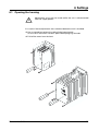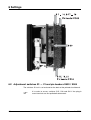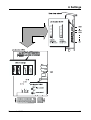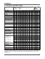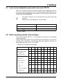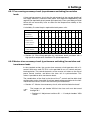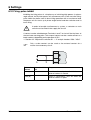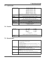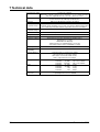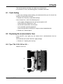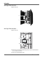
1
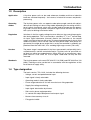
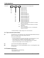
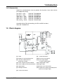
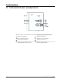
Thyristor Power Units
B 70.9040.0
Operating Instructions
02.06 /00089951
Contents
1
Introduction ......................................................................................... 7
1.1
Preface .................................................................................................................... 7
1.2 Typographical conventions ................................................................................... 8
1.2.1 Warnings .................................................................................................................. 8
1.2.2 Note signs ............................................................................................................... 8
1.3
Description .............................................................................................................. 9
1.4
1.4.1
1.4.2
1.4.3
Type designation .................................................................................................... 9
Type extensions (extra codes) ................................................................................ 10
Standard accessories ............................................................................................ 10
Accessories ............................................................................................................ 11
1.5
Block diagram ...................................................................................................... 11
1.6
Front panel indicators and adjustments ............................................................ 12
2
Operating modes .............................................................................. 13
2.1
Phase-angle control with soft start and current limiting .................................. 13
2.2
Burst-firing operation, for resistive loads .......................................................... 14
2.3
Burst-firing operation for transformer loads and loads with a high positive temperature coefficient TC (mixed operation) 15
3
Installation ......................................................................................... 17
3.1
Important installation notes ................................................................................ 17
3.2
Filtering and interference suppression .............................................................. 18
3.3
Installation site and climatic conditions ............................................................ 18
3.4 Wall mounting ....................................................................................................... 19
3.4.1 TYA-110/3, 025..100 .............................................................................................. 19
3.4.2 TYA-110/3,150 and TYA-110/3, 250 ...................................................................... 20
3.5 DIN rail mounting ................................................................................................. 21
3.5.1 TYA-110/3, 025 ..100 ............................................................................................. 21
4
Electrical connection ........................................................................ 23
4.1
4.1.1
4.1.2
4.1.3
Connection diagram ............................................................................................
Type TYA-110/3, 025, - 050, - 075, - 100, ... ..........................................................
Type TYA-110/3, 150, ... .........................................................................................
Type TYA-110/3, 250, ... .........................................................................................
4.2
Single-phase operation: line/phase – N ............................................................. 26
4.3
Single-phase operation: phase – phase ............................................................. 27
4.4
Star configuration: with star point connected to N .......................................... 28
4.5
Open delta configuration (six-wire circuit) ........................................................ 29
Power units 02.06
23
25
25
25
3
Contents
4.6
Free-running economy circuit, purely resistive loads ....................................... 30
4.7
Master-slave economy circuit, with resistive/inductive loads ......................... 31
5
Commissioning ................................................................................. 33
5.1 Adjust control input (full wave) ........................................................................... 33
5.1.1 Setting the maximum power output ....................................................................... 33
5.1.2 Input signal attenuator ........................................................................................... 33
5.2
Setting the base load ........................................................................................... 34
5.3 Setting the current limit ....................................................................................... 35
5.3.1 Alteration of the current limit Imax, as a function of the voltage on Terminal 9 ..... 36
5.4
Setting the phase angle for the first half-wave ................................................. 36
5.5 Load and part-load failure monitoring ............................................................... 37
5.5.1 Setting the threshold for load failure indication ................................................ 37
5.5.2 Setting for master-slave and free-running economy circuit ............................ 38
5.6
External changeover of operating modes ......................................................... 38
5.7
Blown fuse indication .......................................................................................... 38
6
Settings .............................................................................................. 39
6.1
Opening the housing ............................................................................................ 39
6.2
Adjustment switches S1 — 21 and pin headers X503 / X504 .......................... 40
6.3
Summary of possible settings ............................................................................ 42
6.4 Control inputs ....................................................................................................... 43
6.4.1 Combinations of external potentiometer and electronic controller ........................ 44
6.5
Subsidiary control loops ...................................................................................... 45
6.6
Actual (power) output .......................................................................................... 46
6.7
Load current adaptation (only with extra code TR/T0) ..................................... 47
6.8
Select operating modes and load types ............................................................ 47
6.9 Economy circuit .................................................................................................... 48
6.9.1 Free-running economy circuit (asynchronous switching) for resistive loads ......... 49
6.9.2 Master-slave economy circuit (synchronous switching) for resistive and transformer
loads 49
6.10 Firing-pulse inhibit ............................................................................................... 50
7
Technical data ................................................................................... 51
7.1
Load circuit ........................................................................................................... 51
7.2
Control ................................................................................................................... 51
7.3
General data ......................................................................................................... 51
4
Power units 02.06
Contents
8
Faults .................................................................................................. 53
8.1
Fault-finding .......................................................................................................... 53
8.2
8.2.1
8.2.2
8.2.3
Replacing the semiconductor fuse ....................................................................
Type TYA-110/3, 025 to 100, ... ..............................................................................
Type TYA-110/3, 150, ... .........................................................................................
Type TYA-110/3, 250, ... .........................................................................................
Power units 02.06
53
53
54
54
5
Contents
6
Power units 02.06
1 Introduction
1.1 Preface
B
Please read these operating instructions before starting up the instrument.
Keep them in a place that is accessible to all users at all times.
Please help us to improve this manual.
Your suggestions will be welcome.
Fax: in Germany
abroad
H
(0661)
6003-862
+49 661 6003-607
If any difficulties arise during commissioning, you are asked not to
carry out any unauthorized manipulation. You could endanger your
rights under the instrument warranty!
Please contact the nearest subsidiary or the main factory in such a
case.
H
When returning chassis, modules or components, the regulations
of EN 100 015 “Protection of electrostatically sensitive components” must be observed. Use only the appropriate ESD packaging for transport.
Please note that we cannot accept any responsibility for damage
caused by ESD (electrostatic discharge).
Power units 02.06
7
1 Introduction
1.2 Typographical conventions
1.2.1 Warnings
The signs for Danger and Caution are used in this manual under the following
conditions:
V
A
E
Danger
This symbol is used where there may be danger to personnel if the instructions are disregarded or not followed accurately!
Caution
This symbol is used where there may be damage to equipment or data if the
instructions are disregarded or not followed accurately!
Caution
This symbol is used if precautions must be taken when handling electrostatically sensitive components.
1.2.2 Note signs
H
v
Note
This symbol is used to draw your special attention to a remark.
Reference
This symbol refers to additional information in other manuals, chapters or
sections.
Footnote
abc1
h
Footnotes are comments that refer to specific parts of the text. Footnotes
consist of two parts:
1) The marking in the text, arranged as continuous superscript numbers.
2) The footnote text at the bottom of the page, in a smaller typeface than the
main text, and preceded by a number and a stop.
Handling instructions
This symbol marks the description of a required action.
The individual steps are indicated by asterisks, for example:
h Disconnect the instrument completely from the supply
h Remove the instrument cover
8
Power units 02.06
1 Introduction
1.3 Description
Application
A thyristor power unit can be used wherevere sizeable resistive or inductive
loads are switched frequently – for instance, in industrial furnaces and plastics
processing.
Operating
modes
The thyristor power units can operate under phase-angle control with adjustable current limiting or in burst-firing mode, depending on the setting of the internal switch. An external switch may also be used to change over the operating mode. In burst-firing mode, the phase angle can be cut back for the first
half-cycle, for driving transformer loads.
Regulation
Variations in the line supply voltage have no effect on the control-loop regulation during operation. This is ensured by a subsidiary V2, P or I2 control loop.
An input signal attentuator (trimmer) permits the restriction of the control
range, and a base load can be set by an external potentiometer. In burst-firing
mode an economy circuit can be used for multi-phase loads. With phase-angle control, the target phase angle that is set by the controller is gradually approached from the initial 180°, thus avoiding high surge currents (soft start).
Versions
The power stage is composed of 2 thyristors connected in anti-parallel, the insulated heatsink, and the control electronics. Thyristor units for up to 50A rated load can either be snapped onto a 35mm DIN rail, or mounted on a basplate fixed to a wall. Units for 75A or higher rated load can only be wallmounted.
Standards
The thyristor power units meet VDE 0160 5.5.1.3 (5/88) and VDE 0106 Part 100
(3/83). Earthing must be carried out in accordance with the regulations of the
local electrical supply utility.
1.4 Type designation
The basic version, TYA-110/3, includes the following features:
- Voltage, current and potentiometer input
- Input signal is freely selectable
- Operating mode is freely selectable
- Phase-angle reduction of 1st half-wave for burst-firing operation
- Supply line voltage monitoring
- Input signal attentuation by trimmer
- Soft start in phase-angle operation
- V2-control with adjustable power level output signal
- Master-slave economy circcuit
- Firing-pulse inhibit
Power units 02.06
9
1 Introduction
TYA-110/3
,
...
,
...
,
..
Thyristor power unit for analog control
025
Load current 25A
050
Load current 50A
075
Load current 75A
100
Load current 100A
150
Load current 150A
250
Load current 250A
024
Rated load voltage 24V 1
042
Rated load voltage 42V 1
115
Rated load voltage 115V 1
230
Rated load voltage 230V 1
265
Rated load voltage 265V 1
400
Rated load voltage 400V 1
460
Rated load voltage 460V 1
500
Rated load voltage 500V 1
TR
Indication of part-load failure or blown fuse through
built-in relay and LED.
TO
Indication of part-load failure or blown fuse through
optocoupler
MS
Master-slave circuit
2 pre-assembled power units on a mounting plate,
ready for connection
1. Rated load voltage = supply voltage for the control electronics
1.4.1 Type extensions (extra codes)
TR
Extended version, with indication of part-load failure (adjustable by trimmer) or
blown fuse through common relay contact and LED.
This version also includes:
- Current limiting (internal, external) and rated current adjustment at I ≤ IN/2
- Free selection of the subsidiary control-loop type (V2, I2 or P).
A free-running economy circuit can be implemented with P-control!
- Power level output signal can be switched to: V2, P, I2
TO
as for TR, but with signaling via optocoupler
MS
Master-slave circuit: 2 pre-assembled power units on a mounting plate, ready
for connection.
1.4.2 Standard accessories
1 Mounting plate for wall-mounting
1 Operating Instructions
10
Power units 02.06
1 Introduction
1.4.3 Accessories
Super-fast semiconductor fuses to protect the thyristors from short-circuits
(no supply line fusing).
32A for IN = 25A,
80A for IN = 50A,
125A for IN = 75A,
160A for IN = 100A,
350A for IN = 150A,
550 A for IN = 250A,
Sales No. 70/00068009
Sales No. 70/00068011
Sales No. 70/00081800
Sales No. 70/00081801
Sales No. 70/00083318
Sales No. 70/00371964
Assembly kit for DIN rail mounting, for 25A and 50A versions,
Sales No. 70/00067312
1.5 Block diagram
(
(1) Load
(9)
Control electronics
(2) Super-fast semiconductor fuse
(10) Trimmer on front panel
(3) Thyristor module with RC
protection network
(11) Error signal output
via relay or optocoupler
(4) Driver stage for thyristor module
(12) Configuration switch
(5) Power supply for control electronics
(13) Signal LEDs
(6) Optocoupler
(14) Master-slave connections
(7) Voltage converter
(15) Output level setting, operating inputs,
power level output signal
(8) Current transformer
Power units 02.06
11
1 Introduction
1.6 Front panel indicators and adjustments
(1) Indicator LED for blown semiconductor fuse (6) Adjustment of threshold for part-load failure
indication (with extra code TR or TO)
(2) LED for current indication
(7) Adjustment of full output
(3) LED for load-failure indication
(8) Adjustment of power level signal
(4) LED for full-output indication
(9) Spring clip to release cover
(5) Adjustment of current limit in phase-angle
(10) Adjustment of phase-angle reduction for 1st half-
operation (with extra code TR or TO)
12
wave in burst-firing operation
Power units 02.06
2 Operating modes
2.1 Phase-angle control with soft start and current limiting
In this mode of operation, the power is regulated by altering the phase angle.
This method is suitable for transformer and resistive loads. During the switchon period the phase-angle is gradually advanced by the controller to provide a
soft start. This prevents high surge currents at switch-on.
Current limiting
For loads with an initial (cold) resistance that is significantly lower than the resistance after warming up, such as Kanthal-Super heater elements, it is advisable to make use of current limiting (only with extra code TR or TO).
While current limiting is in operation, the phase angle during soft start remains
constant.
The maximum permissible effective (rms) current can be adjusted on the front
panel, by using the “current limit” trimmer.
v Section 5.3 “Setting the current limit”
Power units 02.06
13
2 Operating modes
2.2 Burst-firing operation, for resistive loads
In this mode of operation, the power is regulated by changing the number of
full-wave cycles of the supply line voltage which are switched on during each
control period. This method is used for purely resistive loads which have a
cold resistance that is roughly the same as the hot resistance.
Since switching only takes place at the zero-crossing points, this mode of
operation produces very little RF-interference.
The internal switch S20 can be used to adjust the duty cycle to suit the system
being controlled.
v Section 6.2 “Adjustment switches S1 — 21 and pin headers X503 / X504”
Cycle time
S 20
Variable cycle time
1
The control unit uses the shortest available cycle time
(for fast control loops)
Fixed cycle time (≈ 500ms)
Used for transformer loads, slow control loops
14
2
Power units 02.06
2 Operating modes
2.3 Burst-firing operation for transformer loads and loads with a
high positive temperature coefficient TC (mixed operation)
H
Soft start
It is not possible to change over to phase-angle control in this
mode of operation.
For the first switch-on of the thyristor power unit, or after being switched off by
inhibiting the firing-pulses, after a supply line interruption, or if the setpoint
was switched off for more than 8seconds, there will always be a short phaseangle controlled start (area a in the diagram).
After this soft start, the controller switches over automatically to burst-firing
operation if the given setpoint is larger than the minimum setpoint + 10% of
the setpoint range (area b in the diagram).
Example:
Setpoint range 2 — 10V
The changeover to burst-firing operation takes place at
2V + 10% of 8V = 2V + 0.8V = 2.8V
After this changeover, the power output is regulated to follow the setpoint input provided.
H
If the power unit runs into current limiting1 during the phase-angle
controlled start, then the output is regulated according to the maximum current given by the curent limit setting, even for low levels of
the setpoint input.
1. with extra codes TR/TO
Power units 02.06
15
2 Operating modes
For transformer loads, the thyristor power unit operates in burst-firing mode
with a cut-back (retarded) phase-angle for the first half-wave. The factory setting is an angle α = 90°. This value can be altered on the front panel over a
range α = 0 — 90°.
v Section 5.4 “Setting the phase angle for the first half-wave”
H
16
We recommend that this setting is not changed!
Power units 02.06
3 Installation
3.1 Important installation notes
Safety
regulations
- The choice of cable, installation and electrical connection of the instrument
must meet the requirements of VDE 0100 “Regulations for the Installation of
Power Circuits with nominal voltages below 1000 V AC” or the
corresponding local regulations.
- Electrical installation must only be performed by properly qualified
personnel.
- The unit must be completely disconnected from the supply line (on all
poles) if there is a risk of contact with live parts during work on the unit.
Fusing
V
Interference
suppression
- In the event of a short-circuit in the load circuit, the power unit is protected
by the built-in semiconductor fuse.
v Section 8.2 “Replacing the semiconductor fuse”
- Do not connect any additional loads to the output load terminals.
- The electromagnetic compatibility (EMC) meets the standards and
regulations cited in the technical data.
v Section 7 “Technical data”
Wiring
Connections
Load and control cables should be laid separately, as far as feasible.
The appropriate fuses for control circuitry (e.g. 2A, type Neozed) should be
used to protect the wiring.
h Check the data given on the nameplate (rated load voltage, load current)
against the data for the system.
h Wire up the connections from supply line – thyristor power unit – load
according to the wiring diagram, and check them
h If the economy circuit configuration is used, check that the rotary electrical
field has clockwise phasing.
h Check the settings for the setpoint inputs
h Check the switch positions
Supply voltage
h Connect the supply voltage for the control electronics as shown in the wiring diagram.
h Link “N/L2” to “V”, unless the economy circuit is being used (slave unit).
Load
connection
The electronic switching devices (2 antiparallel thyristors) are in circuit between the screw connections “U1” and “U2”.
Phasing
The supply voltage for the control electronics and the load voltage must
have the same phase.
h Terminal “L1” must be connected, via a control circuitry fuse, to the same
supply potential as terminal “U1”!
Power units 02.06
17
3 Installation
Switch-on
sequence
The supply voltages for the load and control circuitry must be switched on
at the same time.
A
Control inputs
In no circumstances should the supply voltage for the control
electronics be switched on before the voltage for the load!
This is especially important for operating transformer loads and resitive loads with a large variation between hot and cold resistance!
The control connections (inputs and outputs) are designed for safety separation from the supply line input (SELV). In order not to diminish this safety
separation, all connected circuits must also have safety separation. The
auxiliary voltages which are required must be safe extra-low voltages
(SELV).
V
Connections must only be wired up by properly qualified
personnel!
3.2 Filtering and interference suppression
In order to prevent radio-frequency interference, such as would occur with
phase-angle control, electrical apparatus and systems must have interference
suppression implemented.
The control electronics of the thyristor power units conforms to the EMC Directive EN 61 326.
However, modules such as thyristor power units have no use by themselves,
but only as a component function within a system. For this reason, the load
circuit of the power unit must have suitable interference suppression filters fitted by the system provider.
Specialist companies have appropriate ranges of filters available to deal with
these problems. Such filters are normally supplied as complete modules that
are ready to be connected up.
3.3 Installation site and climatic conditions
The installation site should be, as far as possible, free from vibration. Electromagnetic fields, caused by equipment such as motors and transformers,
should be avoided. The ambient temperature at the installation site must be
within the range 0 to 45°C (measured about 100 mm below the unit) and the
relative humidity must be ≤ 75%. The thyristor power unit is intended for use
in dry rooms. The inside of the unit must be kept free from conductive dirt and
corrosive gases.
The thyristor power unit must be mounted vertically, to ensure good convection cooling. If it is mounted in a switchgear cabinet, adequate ventilation must
be provided. There must be at least 100 mm free space below, and 150 mm
18
Power units 02.06
3 Installation
above the unit. The thyristor power unit has enclosure protection IP00, and so
it must be mounted in such a way that bodily contact is prevented (built-in
unit).
V
Incorrect use
The heatsink can become very hot in operation!
- The unit is not suitable for installation in areas with an explosion hazard
(Ex areas).
- The installation site should be free from vibration, dust, and corrosive
media.
Ambient
conditions
- Side-by-side mounting of units is permitted
- Relative humidity ⱕ 75 %, no condensation
- Ambient temperature range: 0 to 45 °C
Storage temperature range: -10 to 70 °C
3.4 Wall mounting
h Fix the aluminium mounting plate to the heatsink, using the cheese-head
screws provided.
h Fix the thyristor power unit with its mounting plate to the wall, using four
screws.
3.4.1 TYA-110/3, 025..100
Power units 02.06
19
3 Installation
3.4.2 TYA-110/3,150 and TYA-110/3, 250
20
Power units 02.06
3 Installation
3.5 DIN rail mounting
h Fix the DIN rail
h Snap the thyristor power unit and its mounting plate onto a standard rail (to
DIN EN 50 022) and lock it in place with the lever. This type of mounting is
only possible for thyristor power units up to 50A rated current.
3.5.1 TYA-110/3, 025 ..100
Power units 02.06
21
3 Installation
22
Power units 02.06
4 Electrical connection
4.1 Connection diagram
The diagram shows the various connections that are available at the plug-in
screw terminals.
V
Only properly qualified personnel are permitted to make electrical
connections!
h Disconnect the equipment completely (on all poles) from the supply line
h Connect the control cables (conductor cross-section 0.2 — 2.5 mm2) to the
screw terminals. Use cable lugs to DIN 46 212 for the load connections.
Tools required
1 screwdriver, 3 mm blade (max.)
1 socket wrench, 10 mm (for TYA-110/3, 100)
1 socket wrench, 13 mm ( for TYA-110/3,150 and TYA-110/3, 250)
Power units 02.06
23
4 Electrical connection
Connection for
Supply voltage for control electronics;
link V to N/L2, unless economy circuit is being used
Pin assignment
L1
(line / phase 1)
N/L2 (neutral / phase 2)
V
Load connection
U1
U2
Current input
(differential input)
12+
Voltage input
(referred to ground)
3⊥
4+
Logic input
Current signal 0/20 mA
12+
Voltage signal 0/10 V
3⊥
4+
Floating contact
4+
5 (+10V, 2mA)
Symbol
External manual adjustment with 5 kΩ potentiometer 3 Start (⊥)
(via voltage input)
4 Slider
5 End (+10V, 2mA)
Firing-pulse inhibit input IK ≈ 1mA
(make or break contact)
6⊥
7+
or
Load-failure output with relay,
switching capacity 5A at 230 V AC, resistive load.
Relay drops out if fault occurs.
(extra code TR)
16 P pole
15 O break contact
14 S make contact
Load failure output with optocoupler
ICmax. = 2mA UCEO max. = 32V
(extra code TO)
15 Collector
16 Emitter
External changeover of operating mode
(phase-angle or burst-firing operation)
6⊥
8+
Actual (power) output 0 — 10V
Imax ≈ 2mA
10+
6⊥
Master-slave connection for
master-slave economy circuit
6⊥
11
12
External current limiting
with 5 kΩ potentiometer
5 Start (+10V, 2mA)
6 End (⊥)
9 Slider
24
Power units 02.06
4 Electrical connection
4.1.1 Type TYA-110/3, 025, - 050, - 075, - 100, ...
4.1.2 Type TYA-110/3, 150, ...
4.1.3 Type TYA-110/3, 250, ...
Power units 02.06
25
4 Electrical connection
4.2 Single-phase operation: line/phase – N
UL
= phase-phase voltage
Ptot = total controlled power
UN
= phase-neutral voltage
IL
= current in phase conductor
UThy = voltage on thyristor power unit IThy = current in thyristor power unit
26
Power units 02.06
4 Electrical connection
4.3 Single-phase operation: phase – phase
UL
= phase-phase voltage
Ptot = total controlled power
UN
= phase-neutral voltage
IL
= current in phase conductor
UThy = voltage on thyristor power unit IThy = current in thyristor power unit
Power units 02.06
27
4 Electrical connection
4.4 Star configuration: with star point connected to N
UL
= phase-phase voltage
Ptot = total controlled power
UN
= phase-neutral voltage
IL
= current in phase conductor
UThy = voltage on thyristor power unit IThy = current in thyristor power unit
28
Power units 02.06
4 Electrical connection
4.5 Open delta configuration (six-wire circuit)
UL
= phase-phase voltage
Ptot = total controlled power
UN
= phase-neutral voltage
IL
= current in phase conductor
UThy = voltage on thyristor power unit IThy = current in thyristor power unit
Power units 02.06
29
4 Electrical connection
4.6 Free-running economy circuit, purely resistive loads
Only possible in
burst-firing
mode with
P-control
UL
= phase-phase voltage
Ptot = total controlled power
UN
= phase-neutral voltage
IL
= current in phase conductor
UThy = voltage on thyristor power unit IThy = current in thyristor power unit
30
Power units 02.06
4 Electrical connection
4.7 Master-slave economy circuit, with resistive/inductive loads
Only possible in
burst-firing
mode
UL
= phase-phase voltage
Ptot = total controlled power
UN
= phase-neutral voltage
IL
= current in phase conductor
UThy = voltage on thyristor power unit IThy = current in thyristor power unit
Power units 02.06
31
4 Electrical connection
32
Power units 02.06
5 Commissioning
5.1 Adjust control input (full wave)
The trimmer (7) “full wave” on the front panel can be used to adjust the thyristor power unit so that the 100% (full wave) firing point is reached at the maximum output signal of the preceding controller.
5.1.1 Setting the maximum power output
h Apply the maximum controller output signal
h Turn the “full wave” trimmer clockwise or counter-clockwise until the green
LED for “full wave” just light up in phase-angle control, and does not light
up in burst-firing mode.
H
When using a logical control output (e.g. from a single-setpoint
controller) the “full wave” trimmer must be turned fully clockwise.
5.1.2 Input signal attenuator
h Turning the “full wave” trimmer counter-clockwise limits the maximum
power output of the thyristor power unit.
When using the free-running economy circuit, both thyristor power units
must be adjusted as described above.
When using the master-slave economy circuit, the adjustment is only made
on the master power unit.
v Section 4.6 “Free-running economy circuit, purely resistive loads” und
Section 4.7 “Master-slave economy circuit, with resistive/inductive loads”
Power units 02.06
33
5 Commissioning
5.2 Setting the base load
A base load can be set, in addition to the analog current input and the potentiometer input. Since these input signals are added together, the input signal
gain must be corrected by adjusting the “full wave” trimmer (7).
For instance, if a heating system is to be operated with a 33% base load, with
the other 66% of the output being regulated by the controller, then the procedure is as follows:
Calculate the reduction factor of the controller signals.
In this example it would be 100% : 66% = 1.5.
Multiply this factor by the intended base load setting.
In this case: 1.5 x 33% = 50%.
The factor 0.5 means that the external potentiometer must be set to 50% of
the full-scale value.
Adjustment:
h Set the potentiometer to the calculated fraction of the full scale (e.g. 50%)
h Apply the maximum current (e.g. 20mA) to the current input
h Turn the “full wave” trimmer clockwise or counter-clockwise until the green
LED for “full wave” just light up in phase-angle control, and does not light
up in burst-firing mode.
34
Power units 02.06
5 Commissioning
5.3 Setting the current limit
Internal current
limiting
Current limiting is only possible in the phase-angle mode of control.
h The trimmer (5) “current limit” on the front panel can be used to limit the
effective (rms) value of the load current over a range from 10 — 100% of
the rated current for the thyristor control unit (I ThyN).
1.5 turns clockwise correspond to increasing the threshold by about 10%
of the rated current.
The red LED lights up when the current limit is reached. Current limiting is
achieved by limiting the “ON” phase angle so that the set value for effective
current is not exceeded.
External current limiting
An external voltage signal in the range 0 — 10 V can be applied to Terminal 9
to influence the internal current limit I max set by the “current limit” trimmer.
0V means no effect, 10 V means the maximum effect (the threshold is reduced
to the smallest value possible).
Power units 02.06
35
5 Commissioning
5.3.1 Alteration of the current limit Imax, as a function of the voltage on
Terminal 9
With an internal limit of, for example, I max = 0.8 x I Thy , the external range of
variation is only 0 to 8V.
5.4 Setting the phase angle for the first half-wave
In the mode “burst-firing with phase-angle controlled start” the thyristor power
unit retards the firing point for the first half-wave after the start in burst-firing
mode.
The factory setting is an angle α = 90°(electrical). This value can be altered
over the range α = 0 — 90°by the trimmer (10) “angle set”.
The factory setting will be satisfactory in most cases.
H
If it is nevertheless necessary to make an adjustment, then the
minimum switch-on current at the start of the burst is the criterion
for setting the angle α.
Counter-clockwise (left) = advance the firing angle α
Clockwise (right) = retard the firing angle α
36
Power units 02.06
5 Commissioning
5.5 Load and part-load failure monitoring
This function is only available with the extra code TR or TO. If there is a
change in the load resistance during operation, this is detected and indicated
by the part-load failure monitoring.
The signal output is available either as a floating contact (extra code TR) or an
optocoupler (extra code TO). If a part-load fault occurs, the relay drops out or
the collector-emitter of the optocoupler goes high-impedance. The signal output is also produced if there is a blown fuse.
The response threshold can be set by the front-panel trimmer (6) “load fail” to
a value between 20 and 100% of the rated current for the power unit. Partload failure monitoring functions in all operating modes.
H
The load/part-load failure monitoring (low current monitoring) can
also be used for overcurrent monitoring. To implement this, remove
the two jumpers on pin header X504, next to the “angle set” trimmer, turn them through 90° and replace.
v Section 6.2 “Adjustment switches S1 — 21 and pin headers X503 / X504”
5.5.1 Setting the threshold for load failure indication
(Factory setting is 50% of rated load)
h Connect up the load
h Apply full power
h Set the “load fail” trimmer so that the yellow “load fail” LED just goes out.
- turn clockwise (right) = LED lights up
- turn counter-clockwise (left) = LED goes out
h If necessary, the threshold can be reduced by further counter-clockwise rotation, whereby 1.5 turns of the trimmer potentiometer correspond to a load
change of about 10% of the rated curent for the thyristor power unit.
If the load current is below the rated current of the power unit, then the number of turns required is reduced in the same proportion.
If load current IL< 0.5 x IThyN then internal switch S15 must be in position 0.
v Section 6.3 “Summary of possible settings”
Power units 02.06
37
5 Commissioning
Alternative setting:
Simulate a load failure, and then adjust the “load fail” trimmer so that the yellow “load fail” LED just lights up.
5.5.2 Setting for master-slave and free-running economy circuit
H
When using master-slave and free-running economy circuits, the
settings must be made in both thyristor power units.
H
The smallest change of resistance that can be detected is 5% of
the nominal load resistance (10% in an economy circuit).
5.6 External changeover of operating modes
For this to be possible, an external switch must be wired between Terminal 8
and Terminal 6.
Switch
Operating mode
open
burst-firing mode
closed
phase-angle control
H
The external switch can only be used to change from burst-firing to
phase-angle control when the internal switch S3 is open, since this
switch is in parallel with the external switch S.
If the switches S12 and S13 are closed, an external changeover to phaseangle control is not possible.
v Section 6.3 “Summary of possible settings”
5.7 Blown fuse indication
If a short-circuit occurs, the built-in semiconductor fuse switches within half a
supply cycle, to protect the thyristors. When the fuse is blown, the “fuse” LED
lights up,
v Section 8.2 “Replacing the semiconductor fuse”
With extra code TR or TO, an output signal is also available.
v Section 4.1 “Connection diagram”
38
Power units 02.06
6 Settings
6.1 Opening the housing
V
Adjustments must only be made while the unit is disconnected
from the supply power!
It is easier if these adjustments are carried out before the unit is installed.
h Use a screwdriver to lever the spring fixing lug outwards.
On the 150 A and 250 A versions: press both spring lugs inwards.
h Pull off the cover from the front.
Power units 02.06
39
6 Settings
6.2 Adjustment switches S1 — 21 and pin headers X503 / X504
The switches S1 to 21 can be found on the back of the printed circuit board.
H
40
It is easier to access switches S15, S16 and S21 if the plug-in
screw terminals are first pulled off downwards.
Power units 02.06
6 Settings
Power units 02.06
41
6 Settings
6.3 Summary of possible settings
Switch position
Switch number1
factory setting
job-specific setting
Control input
0 — 20mA
4 — 20 mA
0 — 10V
2 — 10V
0 — 5V
1 — 5V
Logic signals 0/10V, 0/5V,
0/20mA or floating contact
Subsidiary control loop
V2
P
I2
Actual power output
V2
P
I2
Load current adaptation IL
IL < 0.5 · IThyN
IL ⱖ 0.5 · IThyN
Firing-pulse inhibit
-external make contact
-external break contact
Operating mode:
Phase-angle control
for transformer/resistive load
Burst-firing mode:
■ for resistive load
■ for transformer load
- R ≈ constant
1
1
2
0
1
0
1
0
1
0
0
0
0
0
0
0
0
1
3
0
4
1
5
0
6
0
7
1
8
0
9
0
10 11 12 13 14 15 16 17 18 19 20 21
1 0 0 0 1 1 0 1 1 1 1 1
0
0
0
0
1
1
1
1
0
0
0
1
0
1
0
0
1
1
0
0
0
1
0
0
0
1
0
1
1
2
1
1
0
0
0
1
0
0
1
R
- -----w- > 1(soft start)
RK
- fixed cycle (500ms)
- variable cycle
Economy circuit
(free-running)
■ for resistive load
(Master-slave)
-master, resistive load
-slave2, resistive load
-master, transformer load
-Slave2, transformer load
1
2
1
2
1
2
2
0
0
1
0
1
0
1
1
1
1
1
1
1
1
1
1
1
2
2
1
0
0
0
0
0
0
1
0
1
0
1
1
0
0
0
0
1
1
0
1
1
0
1
1
1
1
1
1
0
1
0
1
2
1
2
1
2
1
2
2
2
1
1
1
1
1. S5, S6, S8, S9, S15 only have an effect with extra code TR or TO.
2. The jumpers on pin header X503 must be turned through 90°. Section 6.2 “Adjustment switches S1 — 21 and pin headers
X503 / X504”. A changeover to phase-angle control is not possible for burst-firing mode with a transformer load and soft start.
v Section 2.3
42
Power units 02.06
6 Settings
6.4 Control inputs
The internal switches S1, S2, S16, S19, S20 can be used to adapt the thyristor power unit to suit the available control signal (controller output signal).
There are separate voltage and current control inputs. The current inputs (+,-)
are designed for a differential current signal, i.e. they can have a common potential that is up to 10V above or below the ground reference potential (⊥).
If the current and voltage inputs are used simultaneously, they have an additive effect. Both analog and logical controller output signals may be used.
Control signal
Internal switch
Signal start
Signal end
S1
S2
S16
S19
0 mA
20 mA
1
0
0
1
4 mA
20 mA
0
0
0
2
0V
10 V
1
0
0
1
2V
10 V
0
0
0
2
0V
5V
1
0
1
1
1V
5V
0
0
1
2
0
1
1
2
logic levels 0/10V 0/5V, 0/20mA or
floating contact
Analog
control inputs
S20
1
The thyristor power unit can be operated by the following signals (for analog
power regulation):
- voltage signal (Terminals 3, 4)
- current signal (Terminals 1, 2)
- 5 kΩ potentiometer (Terminals 3, 4, 5)
A 10 V source is provided at Terminal 5 for use with a potentiometer. The
switch settings are the same as for a 0 — 10 V signal.
Power units 02.06
43
6 Settings
Logic control
inputs
The thyristor power unit can also be operated by the following logical signals
(e.g. two-state/single-setpoint controller outputs):
(switching pulse bursts on or off):
- current signal 0/20mA (Terminals 1, 2)
- voltage signal 0/10V (Terminals 3, 4)
- floating contact (Terminals 4, 5)
6.4.1 Combinations of external potentiometer and electronic controller
Controller with
current output
The voltage input (Terminals 3, 4) can be used together with the internal 10 V
source and a 5 kΩ potentiometer to provide manual setting.
Switch
Sa
Sb
Automatic
open
open
Manual
closed
closed
H
44
To prevent unintended overdriving on the changeover to manual
operation, Sa should be mechanically coupled to Sb. Otherwise the
two signal sources will be added together for a moment.
Power units 02.06
6 Settings
Controller with
voltage output
This only uses the voltage input of the thyristor power unit. A 5 kΩ potentionmeter is required on Terminals 3 and 5 for manual operation.
Switch
Sc
Automatic operation
position 1
Manual operation
position 2
6.5 Subsidiary control loops
Subsidiary control loops are primarily used to eliminate or compensate external disturbances, such as supply-line fluctuations and changes in resistance
which would have a negative effect on the regulation. A subsidiary V2 control
loop is set up ex-factory. With extra code TR or TO this can be changed to P
or I2 control. The free-running economy circuit must operate with a P control
loop.
v Section 6.2 “Adjustment switches S1 — 21 and pin headers X503 / X504”
H
With P or I2 control loops (extra code TR/TO) a load current adaptation must be made for operating currents that are less than half
the rated load current.
v Section 6.7 “Load current adaptation (only with extra code TR/T0)”
Control
type
V2
Internal switches
S4
S5
S6
1
0
0
Application
- positive TC,
- R ≈ constant
- brightness controls
Power units 02.06
45
6 Settings
P
0
1
0
- temperature-dependent TC
- free-running economy circuit
I2
0
0
1
- negative TC
6.6 Actual (power) output
The factory setting is that the actual (power) signal output corresponds to the
V2 signal at the output of the power unit, and is therefore proportional to the
power in the load (R = constant). With the extra code TR/TO it can be switched
over to a P or I2 signal.
v Section 6.3 “Summary of possible settings”
Actual (power) signal output
Adjust output
Internal switches
S7
S8
S9
V2
1
0
0
P
0
1
0
I2
0
0
1
The signal at the actual (power) output is a voltage in the range 0 — 10V (corresponding to 0 — 100% of the particular measurement range). The trimmer
(8) “output adjust” can be used to adjust the range end value:
Action
Response
Turn trimmer fully clockwise (right)
Measurement range 0 — 100 %
corresponds to a signal 0 — 10V
Turn trimmer fully counter-clockwise Measurement range 0 — 100 %
corresponds to a signal 0 — 5V
(left)
H
With P or I2 control loops, a load current adaptation must be made
for operating currents that are less than half the rated load current!
v Section 6.7 “Load current adaptation (only with extra code TR/T0)”
46
Power units 02.06
6 Settings
6.7 Load current adaptation (only with extra code TR/T0)
With P or I2 control, switch S15 must be in position 0 if the operating current is
less than half the rated current. This is to ensure proper measurement of the
load current for the subsidiary control loop, the current limiting, and the overcurrent / low current detection.
A
The factory setting must not be altered on the 150A and 250A
versions!
(Reserved for service purposes: 1A test mode)
Load current adaptation
Internal switch S 15
IL < 0.5 x IThyN
0
LL > 0.5 x IThyN
1
k factory setting
6.8 Select operating modes and load types
The internal switches S3, S10 — S13 and S20 are used to set the required
mode of operation.
In both phase-angle and burst-firing modes the thyristor power unit basically
operates with a subsidiary V2 control loop. With extra code T0 or TR this can
be changed over from V2 to P or I2 control.
v Section 6.5 “Subsidiary control loops”
Switch
S3
S10 S11 S12 S13 S14 S17 S18 S19
Operating mode:
Phase-angle control
■ for resistive or
transformer load
1
1
0
■ resistive load
0
1
0
■ transformer load
0
0
1
0
0
1
1
1
1
1
1
1
1
1
Burst-firing operation
- R ≈ constant
R
RK
- -----w- > 1
Power units 02.06
1
1
0
0
1
1
2
- fixed cycle (500ms)
2
- variable cycle
1
47
6 Settings
It is not possible to change over to phase-angle control if S12 and S13 are
closed.
v Section 2.3 “Burst-firing operation for transformer loads and loads with a
high positive temperature coefficient TC (mixed operation)”
6.9 Economy circuit
Two single-phase units can be used at any time to implement an “economy
circuit” in a 3-phase system.
The switch settings that are required for this, depending on the type of load
and circuit, can be found in the table.
V
The thyristor power units must always be dimensioned for the
phase-phase voltage, regardless of whether the load is wired in a
star or delta configuration.
It is vital to ensure that the roating electrical field is right-handed,
i.e. clockwise rotation.
Terminal V must be linked to phase L2 on both power units.
v Section 4.6 “Free-running economy circuit, purely resistive loads” and
Section 4.7 “Master-slave economy circuit, with resistive/inductive loads”
48
Power units 02.06
6 Settings
6.9.1 Free-running economy circuit (asynchronous switching) for resistive
loads
A free-running economy circuit has the advantage that the average loading of
the supply network is reduced. Both power units operate independently and
regulate the required 3-phase power quite precisely. Even a possible part-load
failure will not necessarily have an effect on the temperature stability of the
control loop.
A subsidiary P control loop is required for both power units.
Switch
S3
S4
S5
S6
S10
S11
S12
S13
S14
S17
S18
S20
0
0
1
0
1
0
0
0
1
1
1
2
S21
Economy circuit
(free-running)
■ resistive load
(master-slave)
■ resistive load
- master function
0
1
0
1
1
1
1
- slave function
0
1
0
0
2
2
1
0
0
1
1
1
1
2
1
- slave function
0
0
1
1
1
0
2
If S12 and S13 are closed, it is not possible to change over to phase-angle control.
2
2
1
■ transformer load
- master function
1
1
v Section 2.3 “Burst-firing operation for transformer loads and loads with a
high positive temperature coefficient TC (mixed operation)”
6.9.2 Master-slave economy circuit (synchronous switching) for resistive and
transformer loads
In the standard version, the master-slave economy circuit operates with a V2
control. With extra code TO/TR it is also possible to use a P control and partload regulation. The control electronics of the master unit takes on the actual
power control function, and drives the slave unit in synchronization. This
makes it possible to drive transformer loads.
The combination of the fixed cycle time of the V2 control and the delta load
configuration makes it possible to achieve good voltage regulation for the individual load resistances, even in the event of a part-load failure.
v Section 4.7 “Master-slave economy circuit, with resistive/inductive loads”
H
Power units 02.06
The jumpers on pin header X503 of the slave unit must be turned
through 90° !
v Section 6.2 “Adjustment switches S1 — 21 and pin headers X503
/ X504”
49
6 Settings
6.10 Firing-pulse inhibit
Inhibiting the firing pulses is a simple way of switching high powers. In phaseangle control, the thyristor power unit commences with a soft start after firingpulse inhibit has been used. In burst-firing operation with a transformer load,
the power unit first starts up in phase-angle control and then switches over to
burst-firing.
V
In order to be able to disconnect a system, a contactor or main
switch must be fitted in the supply line circuit!
A contact can be wired between Terminals 6 and 7 to shut off the thyristors at
the next zero-crossing point. This external contact can be a make contact or a
break contact, depending on the position of S21.
v Section 6.2 “Adjustment switches S1 — 21 and pin headers X503 / X504”
H
50
Only a make contact can be used as the external contact for a
master-slave economy circuit.
External
contact
Internal switch
S21
Response
make (a)
1
Load is continuously shut off while the
external contact is closed.
break (b)
2
Load is continuously shut off while the
external contact is open.
Power units 02.06
7 Technical data
7.1 Load circuit
Nominal load voltage
Continuous load
current IL
Load types
Current limiting
Fusing
TSE circuit
Power loss
Control accuracy
24V-20%/+15% AC 45 — 63Hz
42V-20%/+15% AC 45 — 63Hz
115V-20%/+15% AC 45 — 63Hz
230V-20%/+15% AC 45 — 63Hz
265V-20%/+15% AC 45 — 63Hz
400V-20%/+15% AC 45 — 63Hz
460V-20%/+15% AC 45 — 63Hz
500V-20%/+15% AC 45 — 63Hz
(supply voltage for control electronics = nominal load voltage)
25A, 50A, 75A, 100A, 150A, 250A
resistive and resistive-inductive loads (B ≤ 1.2 Tesla)
With phase-angle control, the load current can be adjusted over the range
10 — 100% IN by a trimmer on the front panel.
The limiting is based on the rms value of the load current.
super-fast semiconductor fuse
RC network as standard
≈ 1.3V x IL (A)
Supply voltage fluctuations within the tolerance range (-20%/+15%)
are accurately compensated.
Fluctuations ≤ 0.5%.
7.2 Control
Control signal
Input signal
attenuation
0 (4) — 20mA
RI = 50 Ω
0 (2) — 10V
RI = 25kΩ
0 (1) — 5V
RI = 12kΩ
0/10V (0/5V)
RI = 12kΩ
0/20mA
RI = 50Ω
floating contact
or
manual control by an external 5 kΩ potentiometer
adjustment range 100 — 20%
7.3 General data
Circuit variants
Operating modes
Features
Subsidiary control
types
Power units 02.06
- single-phase operation
- star circuit with accessible star point
- open delta circuit
- economy circuit using master-slave principle and subsidiary V2 control
in burst-firing operation
- free-running economy circuit (star or delta) only with subsidiary P control
in burst-firing operation
- phase-angle control for resistive and transformer loads, with soft start
(with current limiting for extra codes TR, TO)
- burst-firing operation for resistive or transformer load
Two single-phase units can be linked to form an economy circuit for burst-firing
operation.
- free-running economy circuit for resistive loads
- master-slave economy circuit for resistive and transformer loads
V2 control as standard.
With extra code TR or TO: free choice of V2, P, I2 control via internal switches.
51
7 Technical data
V2 signal as standard.
With extra code TR or TO: free choice between V2, P, or I2 signal via internal
switches, adjustable from 0 — 5V to 0 — 10V. Imax ≈ 2mA.
Electrical connection Control wiring by screw terminals for conductor cross-sections 0.2 — 2.5mm2.
Load connections by cable lugs to DIN 46 212.
Protection
IP00 as per EN 60 529, heatsink is grounded
Permitted ambient
0 — 45°C
temperature range
Permitted current derated by 2% for each °C increase in ambient temperature;
the maximum permissible ambient temperature must not exceed 60°C.
Permitted storage
-10 to +70°C
temperature range
Climatic conditions
rel. humidity ≤ 75% annual mean, no condensation
Cooling
natural convection
Operating position
vertical
Operating conditions
The thyristor power unit is designed as a built-in unit to:
VDE 0160 5.5.1.3 (5/88)
VDE 0106 Part 100 (3/83)
pollution degree 2 to VDE 0110 Part 1 4.2 (1/89)
overvoltage category Ü III to VDE 0160 5.7 (5/88)
Test voltage
to VDE 0160 Table 4 (6/88)
Electromagnetic
Control electronics to EN 61 326
compatibility
Creepage distance
control electronics to load circuit ≥ 10mm
control electronics to housing ≥ 10mm
Unit can be connected to SELV circuits.
SELV = Seperate Extra Low Voltage
Housing
TYA110/3,
25 (50)
110 x 195 x 152mm
TYA110/3,
75 (100)
125 x 195 x 170mm
TYA110/3, 150 (250)
150 x 220 x 280mm
Weight
TYA110/3,
25 (50)
2.8 kg
TYA110/3,
75 (100)
3.7 kg
TYA110/3,
150
8.6 kg
TYA110/3
250
9.0 kg
Standard
1 mounting plate for wall-mounting
accessories
1 Operating Instructions B 70.9040
Actual (power) output
52
Power units 02.06
8 Faults
The thyristor power unit does not require any maintenance.
In the event of a fault, the following points should be observed:
8.1 Fault-finding
If faults occur during commissioning, we recommend that you first check the
positions of the internal switches.
v Section 6.3 “Summary of possible settings”
If the fault persists, check the following items:
- Is the supply voltage present for the thyristor power unit?
Check the phase sequence as well.
- Are all other connections also correct?
- Is the controller operating properly?
Check the operation manually, by using an external potentiometer.
v Section 6.4 “Control inputs”
8.2 Replacing the semiconductor fuse
If the red LED “fuse” lights up, this means that a semiconductor fuse has
blown.
h Disconnect the system from the supply voltage.
v Section 6.1 “Opening the housing”
8.2.1 Type TYA-110/3, 025 to 100, ...
Wrench 10 mm a/f
Power units 02.06
53
8 Faults
8.2.2 Type TYA-110/3, 150, ...
Wrench 13 mm a/f
8.2.3 Type TYA-110/3, 250, ...
Wrench 13 mm a/f
h Remove the two hexagonal head fixing screws (1) for the semiconductor
fuse, and take out the fuse.
h Insert a new semiconductor fuse!
54
Power units 02.06
8 Faults
h Replace the fixing screws.
h Re-assemble the housing
A
Replacement
fuses
v Section 1.4.3 “Accessories”
V
Power units 02.06
Use only original replacement fuses. If other fuses are used, this
will invalidate the warranty!
The pcbs carry supply line voltages. Work on the circuitry must
therefore only be carried out while the equipment is completely
disconnected from the supply!
To avoid dangerous situations, follow the regulations for “Working
on live equipment“ (VDE 0100 Part 410).
55
JUMO GmbH & Co. KG
JUMO Instrument Co. Ltd.
JUMO Process Control, Inc.
Street address:
Moltkestraße 13 - 31
36039 Fulda, Germany
Delivery address:
Mackenrodtstraße 14
36039 Fulda, Germany
Postal address:
36035 Fulda, Germany
Phone: +49 661 6003-0
Fax:
+49 661 6003-607
E-mail: [email protected]
Internet: www.jumo.net
JUMO House
Temple Bank, Riverway
Harlow, Essex CM20 2TT, UK
Phone: +44 1279 635533
Fax:
+44 1279 635262
E-mail: [email protected]
Internet: www.jumo.co.uk
8 Technology Boulevard
Canastota, NY 13032, USA
Phone: 315-697-JUMO
1-800-554-JUMO
Fax:
315-697-5867
E-mail: [email protected]
Internet: www.jumo.us