1
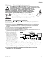
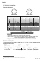
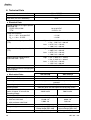
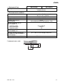
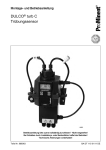
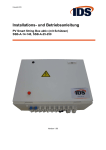
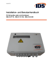
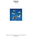
GEL 207 / 208 / 209 / 219
Magnetisch-inkrementale Drehimpulsgeber
Magnetic Incremental Encoders
Betriebsanleitung
Operating Instructions
Inhalt
Contents
1.
2.
3.
4.
5.
6.
1.
2.
3.
4.
5.
6.
Allgemeine Sicherheitshinweise ......... 3
Einleitung ........................................... 4
Typenschlüssel .................................. 5
Mechanischer Einbau......................... 6
Elektrischer Anschluss ....................... 8
Technische Daten ............................ 10
Irrtum und technische Änderungen
vorbehalten
General safety instructions .............. 13
Introduction...................................... 14
Type code........................................ 15
Mechanical assembly ...................... 16
Electrical connection........................ 18
Technical Data................................. 20
Right to technical changes and
errors reserved.
2006-11
Doc. No. DS19-207
Lenord, Bauer & Co. GmbH
Dohlenstrasse 32
46145 Oberhausen • Germany
Fon: +49 (0)208 9963-0 • Fax: +49 (0)208 676292
Internet: http://www.lenord.de • E-Mail: [email protected]
2
GEL 207…219
Deutsch
1. Allgemeine Sicherheitshinweise
Zur Erhaltung der Funktionsfähigkeit des Drehimpulsgebers unbedingt folgende Punkte
beachten:
• Drehimpulsgeber nur über eine flexible Kupplung mit der Antriebswelle verbinden
• Drehimpulsgeber vor mechanischen Beschädigungen schützen (bei Einbau und
Betrieb, siehe dazu die Handhabungshinweise in Kapitel 4).
• Einbau-, Anschluss- und Service-Arbeiten nur von qualifiziertem und geschultem
Fachpersonal durchführen lassen, unter Berücksichtigung der einschlägigen
Unfallverhütungs- und Sicherheitsvorschriften sowie der Angaben in dieser
Betriebsanleitung. Drehimpulsgeber nicht öffnen oder auseinander nehmen.
Notwendige Reparaturen dürfen nur von LENORD+BAUER oder einer davon ausdrücklich ermächtigten Stelle durchgeführt werden.
• Die in der Produktdokumentation angegeben Grenzwerte unbedingt einhalten.
• Buchstabenanordnung in der Steckerbelegung (Kapitel 5) beachten: Ein häufig
auftretender Fehler ist das spiegelbildliche Anschließen von Leitungen an den
Gegenstecker.
Drehimpulsgeber nur bestimmungsgemäß verwenden:
Die Drehimpulsgeber GEL 207…219 sind ausschließlich für Messaufgaben im industriellen und gewerblichen Bereich bestimmt. Mit ihnen können Positionen, Längen,
Winkel oder Drehzahlen gemessen werden.
Sie gelten als Zubehörteil einer Anlage und erfordern den Anschluss an eine spezielle
Auswertelektronik, wie sie ein Positioniercontroller oder ein elektronischer Zähler
enthält.
Zur bestimmungsgemäßen Verwendung gehört auch, dass alle in der Produktdokumentation gegebenen Hinweise beachtet werden.
Eine andere oder darüber hinausgehende Verwendung gilt als nicht bestimmungsgemäß. Für hieraus entstehende Schäden haftet die Firma LENORD, BAUER & CO.
GMBH nicht.
Hinweis in eigener Sache
Die Betriebsanleitung wurde mit größter Sorgfalt erstellt. Es kann jedoch keine Gewähr für
Fehlerfreiheit übernommen werden.
Die Betriebsanleitung ist bestimmt für den Betreiber bzw. Anlagenbauer sowie dessen
Personal. Bitte bewahren Sie sie sorgfältig auf, so dass sie auch für einen möglichen
späteren Serviceeinsatz am Drehimpulsgeber zur Verfügung steht. Bei Weitergabe des
Gebers an Dritte bitte auch diese Betriebsanleitung mitgeben.
GEL 207…219
3
Deutsch
2. Einleitung
Einsatzbereich
Die Drehimpulsgeber GEL 207…219 sind robuste Signalgeber für die Messung von
Rotationsbewegungen oder Positionen. Sie sind für den Einsatz in rauer Umgebung
geeignet, da sie eine hohe Beständigkeit gegen Betauung, Spritz- und Kondenswasser
sowie einen großen Temperaturbereich von 0 °C bis +70 °C, optional sogar von -20 °C bis
+85 °C aufweisen.
Als Ausgangssignale dienen zwei um 90° phasenversetzte Rechtecksignale und – je nach
Ausführung – deren inverse Signale, wodurch eine eindeutige Richtungserkennung und
eine hohe Datensicherheit gegeben sind. Ein optionaler Referenzimpuls kann zum Kalibrieren der Anlage herangezogen werden.
Aufbau und Ausführungen
Die Drehimpulsgeber besitzen ein berührungsloses magnetisches Abtastsystem (Magnetfeldsensor) und ein Zahnrad als Maßverkörperung. Sie sind mit verschiedenen Wellendurchmessern und -längen sowie mit verschiedenen axialen und radialen Stecker- oder
Kabelabgängen und unterschiedlichen Flanschausführungen lieferbar. Die Spannungsversorgung beträgt je nach Typ 5 V oder 10…30 V DC.
Optionen enthalten z.B. einen Kondenswasserstopfen oder einen zusätzlichen Feuchtigkeits- und Vibrationsschutz.
Funktionsprinzip
Das Magnetfeld des Sensors im Drehimpulsgeber wird durch das sich drehende Zahnrad
(Maßverkörperung) verändert. Die Magnetfeldänderung wird vom Sensor ausgewertet und
in entsprechende sinusförmige Messsignale umgesetzt. Eine interne Auswertelektronik
generiert daraus die rechteckförmigen Ausgangssignale.
Signalmuster
a) V, VN
360° el.
Spur 1
90°
UB
10 ... 30 VDC
Spur 2
US
HTL
tF
Spur N
(Option)
tF: Flankenabstand bei 200 kHz ≥ 0,6 µs (gilt für alle Signalmuster)
b) T, TN;
U, UN;
X, XN
Spur 1
Spur 1
Spur 2
T(N)
U(N)
X(N)
UB
5 VDC ± 5%
10 ... 30 VDC
10 ... 30 VDC
US
TTL
TTL
HTL
Spur 2
Spur N
(Option)
Spur N
Signaldarstellung für Rechtslauf; UB = Betriebsspannung, US = Signalamplitude
4
GEL 207…219
Deutsch
3. Typenschlüssel
GEL
___ - _ _ _____ _ _ _ _
Typ (siehe Maßbilder Seite 7)
207
208
209
219
mit Synchronflansch
mit Klemmflansch
mit Lagerbock und erhöhter Wellenbelastung
mit Rechteckflansch und erhöhter Wellenbelastung
Signalmuster (siehe Seite 4)
T
U
V
X
UB = 5 VDC, Logikpegel TTL
UB = 10…30 VDC, Logikpegel TTL
UB = 10…30 VDC, Logikpegel HTL
UB = 10…30 VDC, Logikpegel HTL
Referenzsignal
–
N
ohne Referenzsignal (Standard)
mit Referenzsignal (Option)
Impulszahl (Inkremente pro Umdrehung)
10 … 136.192
Stecker/Kabelabgang
A
B
C
D
6-poliger Stecker, axial
6-poliger Stecker, radial
12-poliger Stecker, axial
12-poliger Stecker, radial
F
G
H
I
6-adriges Kabel, axial
6-adriges Kabel, radial
10-adriges Kabel, axial
10-adriges Kabel, radial
Wellendurchmesser/Länge (in mm)
0
1
2
6/10, Standard (nur GEL 207)
10/20, Standard (nur GEL 208)
16/28, Standard (nur GEL 209/219)
6/10 (nur GEL 208)
8/27 (nur GEL 207/208)
4
5
6
7
10/20 (nur GEL 207)
10/20 Scheibenfeder (nur GEL 207/208)
12/27 (nur GEL 207/208)
12/27 Scheibenfeder (nur GEL 207/208)
Schutz der Elektronik
0
1
2
ohne zusätzlichen Schutz
Feuchtigkeitsschutz
Vibrationsschutz
3
4
5
Feuchtigkeits- und Vibrationsschutz
Feuchtigkeitsschutz und Kondenswasserauslass
Feuchtigkeits- und Vibrationsschutz und
Kondenswasserauslass
Temperaturbereich
1
0 °C … +70 °C
3
-20 °C … +85 °C (Option)
GEL 207…219
5
Deutsch
4. Mechanischer Einbau
Wichtige Hinweise
Bitte sorgen Sie bei der Montage, der Inbetriebnahme und im laufenden Betrieb dafür,
dass alle von uns definierten Spezifikationen (z. B. Umgebungsbedingungen, Versorgungsspannung, Wellenbewegung ...) und die geltenden Unfallverhütungsvorschriften
eingehalten werden.
Die Nichteinhaltung und die Nichtbeachtung der folgenden Hinweise können zu Fehlfunktionen führen.
Den Drehimpulsgeber weder teilweise noch ganz öffnen
und/oder demontieren.
Sie könnten ihn beschädigen und die weitere Funktion
beeinträchtigen.
Drehimpulsgeber und Antriebswelle nicht mit einer starren
Kupplung verbinden.
Es könnten zu hohe Kräfte auf die Lagerung ausgeübt werden. Verwenden Sie elastische, aber drehsteife Kupplungen! Sie können
solche von uns beziehen (bitte kontaktieren Sie uns für nähere
Informationen).
Nicht auf das Gehäuse und die Welle schlagen oder treten.
Dies könnte zu äußeren und inneren Beschädigungen des Drehimpulsgebers führen.
Die Welle nicht anbohren oder anschleifen.
Dies könnte Beschädigungen im Inneren des Drehimpulsgeber verursachen.
Keine höheren axialen oder radialen Kräfte auf die Welle
ausüben, als in den technischen Daten angegeben.
Drehimpulsgeber so montieren, dass die Funktion des Gerätes
nicht beeinträchtigt wird.
Sie können spezielles Montagezubehör von uns beziehen (bitte
spezielles Geberzubehör-Datenblatt anfordern).
Drehimpulsgeber mit Kondenswasserverschraubung (Sonderausführung) so einbauen, dass der Stopfen nach unten zeigt.
Geeignete ESD-Schutzmaßnahmen treffen gemäß DIN EN
100015-1 (CECC 00015-1), siehe Seite 9.
6
GEL 207…219
Deutsch
Maßbilder
(alle Abmessungen in mm)
GEL 207
Synchroflansch
D
h6
6
8
10
12
L
10
27
20
27
Standard
für
← GEL 207
← GEL 208
GEL 208
Klemmflansch
ExzenterKlemmstücke für
die Flanschbefestigung und
weitere Montageteile lieferbar
(siehe Geberzubehör-Datenblatt)
GEL 209
Lagerbock
GEL 219
Rechteckflansch
(Maßbild Kondenswasserauslass siehe Seite 11.)
GEL 207…219
7
Deutsch
5. Elektrischer Anschluss
Kabel- und Steckerbelegung
9
1
F
A
B
10
2
8
12
7
11
E
D
C
6
3
4
6-poliger Stecker
5
12-poliger Stecker
Stecker/Kabel
6-polig
12/10-polig
C
braun
5
weiß
–
–
6
braun
B
weiß
8
rosa
–
–
1 schwarz
D
grau
3
violett
–
–
4
gelb
F
gelb
12
rot
A
grün
10
blau
–
–
2
–
–
–
11
–
Signalspannung (US)
Signal/Funktion
V
VN
T, U, X
TN, UN, XN
Spur 1
Spur 1
Spur 1
Spur 1
–
–
Spur 1
Spur 1
Spur 2
Spur 2
Spur 2
Spur 2
–
–
Spur 2
Spur 2
–
Spur N
–
Spur N
–
–
–
Spur N
UB: +10…30 V (U, V, X) oder +5 V ± 5% (T)
0 V (GND, Bezugsmasse)
+ Sense (UB)
– Sense (GND)
V/VN, X/XN
HTL (10…30 V)
T/TN, U/UN
TTL (5 V)
Erläuterungen:
• Kabelabgang: Abschirmung auf der Drehimpulsgeber-Seite nicht
angeschlossen
• Sense-Funktion: Bei Nichtverwendung die freien Leitungen mit für die Spannungsversorgung nutzen (Halbierung des Spannungsabfalls
durch Parallelschaltung)
• Nicht aufgeführte Steckeranschlüsse/Kabelfarben sind nicht belegt
Maximale Kabellängen
Die Angaben beziehen sich auf Kabel vom Typ LiYCY 6 (10) × 0,25 mm2 zwischen Drehimpulsgeber und nachgeschalteter Elektronik.
• TTL 1)
(T/TN, U/UN)
f=
L=
• HTL (bei UB = 20 V) f =
(V/VN, [X/XN])
L=
1)
8
≤ 100 kHz
200 m
≤ 20 kHz
200 [100] m
200 kHz
145 m
50 kHz
80 [40] m
100 kHz
40 [20] m
200 kHz
20 [10] m
Die angegebenen Längen gelten bei Verwendung eines Netzteils mit Sense-Regelung
GEL 207…219
Deutsch
EGB-Hinweise
(Elektrostatisch gefährdete Bauelemente)
Wie bei jedem elektronischen Gerät sind auch beim Anschluss der Drehimpulsgeber EGB-Vorsichtsmaßnahmen zu treffen. Grundsätzlich gilt, dass
elektronische Baugruppen – insbesondere Steckerstifte und
Anschlussdrähte – nur dann berührt werden sollen, wenn dies
wegen daran vorzunehmender Arbeiten unvermeidbar ist. Der genaue
Umfang der Schutzmaßnahmen richtet sich nach den örtlichen GegebenS T O
heiten. Detaillierte Auskunft gibt die EN 100 015-1 (CECC 00015-1).
Im Allgemeinen ist eine leitfähige, fachkundig geerdete
Arbeitsunterlage in Verbindung mit einem EGB-Armband
ausreichend.
Es ist erforderlich, die Schutzmaßnahmen in regelmäßigen
Abständen auf ihre Wirksamkeit zu überprüfen.
EMV-Hinweise
P
(Elektromagnetische Verträglichkeit)
Zur Verbesserung des elektromagnetischen Umfeldes (EMV) bitte folgende Einbauhinweise beachten:
❏ Möglichst nur Stecker mit Metallgehäuse oder einem Gehäuse aus metallisiertem
Kunststoff und abgeschirmte Kabel verwenden; den Schirm am Steckergehäuse
auflegen
❏ Schirme an beiden Kabelenden möglichst großflächig auflegen
❏ Alle ungeschirmten Leitungen möglichst kurz halten
❏ Erdungsverbindungen möglichst kurz und mit großem Querschnitt ausführen (z. B.
induktionsarmes Masseband, Flachbandleiter)
optionale
❏ Sollten zwischen den MaPegel-Impuls-Umsetzer (PIU)
oder Leitungstreiber (LT)
schinen- und ElektronikErdanschlüssen PotentialAuswertPIU,
Maschine Geber
elektronik
LT
differenzen bestehen oder
auftreten, so ist durch geeignete Maßnahmen dafür zu
Potentialaussorgen, dass über den Kabelgleichsleitung
Nur bei ungünstigen
schirm keine AusgleichsBedingungen wie:
- sehr lange Kabel
Steuerleitungen
ströme fließen können; z. B.
- extreme Störpegel
Potentialausgleichsleitung mit
großem Querschnitt verlegen (siehe Grafik) oder Kabel mit getrennter 2fach-Schirmung
verwenden, wobei die Schirme nur auf jeweils einer Seite aufgelegt werden
❏ Signal- und Steuerleitungen räumlich von den Leistungskabeln getrennt verlegen; ist
dies nicht möglich, paarig verseilte und geschirmte Leitungen (twisted pair) verwenden
und/oder die Geberleitung in einem Eisenrohr verlegen
❏ Die Stromversorgung muss der Installationsart Klasse 0 gemäß Punkt B.3 der
EN61000-4-5 von 1995 entsprechen
GEL 207…219
9
Deutsch
6. Technische Daten
Messschritte pro Umdrehung
Auflösung
10 … 136.192
36° … 0,003°
Fehlergrenze (für max. Auflösung)
0,14°
Elektrische Daten
Betriebsspannung UB für Signalmuster (siehe Seite 4)
U/UN, V/VN, X/XN
T/TN
Leistungsaufnahme
RL = ∞, UB = 10…30 V DC
RL = ∞, UB = 5 V DC
Ausgangspegel für Signalmuster
T/TN (TTL)
Ausgangspegel für Signalmuster
U/UN (TTL)
Ausgangspegel für Signalmuster
V/VN und X/XN (HTL)
Ausgangsfrequenz
Spitzenausgangsstrom zur
Umladung der Kabelkapazität
Mechanische Daten
max. Betriebsdrehzahl
Trägheitsmoment des Rotors
max. Winkelbeschleunigung
Betriebsdrehmoment
Anlaufdrehmoment
Maximale Wellenbelastung
(Angriffspunkt 15 mm von der
Flanschanlage)
Zulässige Wellenbewegung
Lagerlebensdauer (Umdrehungen)
• bei halber Wellenbelastung
• bei maximaler Wellenbelastung
Wellendurchmesser
Flanschausführungen
Masse
10
10 … 30 V DC
5 V DC ± 5%
≤ 1,3 W
≤ 1,0 W
High: ≥ UB - 1,00 V bei I = 10 mA;
≥ UB - 1,20 V bei I = 30 mA
Low: ≤ 0,75 V bei I = 10 mA;
≤ 1,00 V bei I = 30 mA
High: ≥ 4,00 V bei I = 10 mA;
≥ 3,85 V bei I = 30 mA
Low: ≤ 0,75 V bei I = 10 mA;
≤ 1,00 V bei I = 30 mA
High: ≥ UB - 1,80 V bei I = 10 mA;
≥ UB - 2,20 V bei I = 30 mA
Low: ≤ 1,15 V bei I = 10 mA;
≤ 1,55 V bei I = 30 mA
0 Hz … 200 kHz
100 mA
GEL 207/208
-1
10.000 min
GEL 209/219
-1
8.000 min
-5
2
7 · 10 kgm
extrem hoch, da Welle und Messrad (Stahl) verpresst sind
0,03 Nm (< 0,01 Nm mit Kugellagerabdeckscheibe,
Option)
0,05 Nm (0,01 Nm mit Kugellagerabdeckscheibe, Option)
200 N axial
400 N axial
200 N radial
500 N radial
Ankopplung über eine flexible Kupplung empfohlen
6
6
12.600 · 10
6
2.000 · 10
6.600 · 10
6
840 · 10
6 / 8 / 10 / 12 mm
Synchroflansch (GEL 207),
Klemmflansch (GEL 208)
ca. 0,5 kg
16 mm
Lagerbock (GEL 209),
Rechteckflansch (GEL 219)
ca. 0,7 kg
GEL 207…219
Deutsch
Mechanische Daten
Gehäuse
GEL 207/208
GEL 209/219
Stahl, galvanisch verzinkt und schwarz chromatiert,
Durchmesser 58 mm
Umweltbedingungen
Arbeitstemperaturbereich
0 … +70 °C (Standard);
-20 … +85 °C (Option)
-20 … +85 °C
-40 … +105 °C
IP 65;
Betriebstemperaturbereich
Lagertemperaturbereich
Schutzart nach DIN EN 60529
mit Kondenswasserauslass (Option): IP 64
Vibrationsfestigkeit nach
DIN EN 60068-2-6
Frequenzbereich
Spitzenbeschleunigung
Frequenzzyklen
Schockfestigkeit nach
DIN EN 60068-2-27
Isolationsfestigkeit nach VDE 0660
Teil 500 Ausgabe 08/00 oder DIN
EN 60439-1
Elektromagnetische Verträglichkeit
Kondenswasserauslass:
GEL 207…219
10 … 2.000 Hz
2
100 m/s
10
2
Spitzenbeschleunigung 1.000 m/s , Dauer 11 ms
Ri > 1 MΩ, bei einer Prüfspannung von 500 V AC
EN 61000-6-1 bis 4
Geber
11
Deutsch
Notizen:
12
GEL 207…219
English
1. General safety instructions
In order to maintain the encoder's functioning please note the following instructions:
• Only use a flexible coupling to connect the encoder to the driving shaft
• Protect the encoder from being mechanically damaged when mounting and
operating, please observe the handling notes given in chapter 4.
• Only skilled personnel are allowed to commission, connect and service these
components while following the current regulations for prevention of accidents and
safety instructions as well as the information given in this manual. Do not open the
encoder nor disassemble it; if repairs are necessary they must only be carried out
by LENORD+BAUER personnel or by a person/company expressly authorized by
LENORD+BAUER.
• Keep to the limit values stated in the product documentation.
• Note the orientation of the characters in the connector's pin layout (see chapter 5).
A common mistake is a mirror image connection of the lines to the plug pins.
Make use of the encoder only as designated:
The encoders GEL 207…219 have been exclusively designed for performing
measuring tasks in industry. They can be used to measure positions, lengths, angles
or speeds.
They are considered to be components of a complete system and need to be connected to a special evaluation electronics such as incorporated in a positioning controller or an electronic counter.
The designated use requires as well the observance of all instructions listed in the
product documentation.
Any use other than specified must be considered as non-designated and, consequently, LENORD, BAUER & CO. GMBH cannot be held responsible for any damage
resulting from such use.
Note
These Operating Instructions have been produced with great care. However, no guarantees can be made for possible errors.
The Operating Instructions are meant for use by the user or system builder as well as their
employees. Please deposit this manual in a safe place for future use, and enclose it with
the encoder when passing it on to another user.
GEL 207…219
13
English
2. Introduction
Scope
The encoders GEL 207…219 are highly resistant to harsh environmental conditions and
are particularly resistant to the effects of condensation. The high temperature range from 0
°C to +70 °C, optional from -20 °C to +85 °C, ensures functional reliability in a wide range
of conditions. The encoder is thus also ideally suited to applications in heavy industry and
in outdoor locations.
Two 90° phase-shifted rectangular signals and, according to the encoder type, their
inverse signals are output by which the direction detection and a high data reliability are
realised. Additionally, an optional reference pulse can be used for calibrating the drive.
Design
The encoders use a contactless magnetic scanning system (magnetic field sensor) and a
toothed wheel which serves as measuring scale.
Various designs include several shaft diameters and lengths as well as different axial and
radial plug and cable outlets and various flange types. The voltage supply is 5 VDC or 10–
30 VDC, according to the encoder type.
Optional designs include a condensed-water outlet or other additional protection measures
against moisture and vibration.
Functional principle
The sensor’s magnetic field inside the encoder is changed by the passing of the built-in
toothed wheel. The change in the magnetic field is evaluated by the sensor and is converted into sinusoidal measuring signals. An internal interpolation electronic generates the
rectangular output signals from the sinusoidal signals.
Signal patterns
a) V, VN
3 6 0 ° e l.
T ra c k 1
9 0 °
U B
1 0 to 3 0 V D C
T ra c k 2
tF
U S
H T L
T ra c k N
( o p tio n )
tF: edge distance at 200 kHz ≥ 0.6 µs (valid for all signal patterns)
b) T, TN;
U, UN;
X, XN
T ra c k 1
T ra c k 1
T ra c k 2
T (N )
U (N )
X (N )
U B
5 V D C ± 5 %
1 0 to 3 0 V D C
1 0 to 3 0 V D C
U S
T T L
T T L
H T L
T ra c k 2
T ra c k N
( o p tio n )
T ra c k N
Signals shown for clockwise movement; UB = supply voltage, US = signal amplitude
14
GEL 207…219
English
3. Type code
GEL
___ - _ _ _____ _ _ _ _
Type (see dimensioned drawings on page 17)
207
208
209
219
with synchro flange
with clamp flange
with mounting foot and extended shaft load
with square flange and extended shaft load
Signal pattern (see page 14)
T
U
V
X
UB = 5 VDC, TTL logic level
UB = 10 to 30 VDC, TTL logic level
UB = 10 to 30 VDC, HTL logic level
UB = 10 to 30 VDC, HTL logic level
Reference signal
–
N
no reference signal (standard)
with reference signal (option)
Pulse number (increments per revolution)
10 to 136,192
Plug/cable outlet
A
B
C
D
6-pole plug, axial
6-pole plug, radial
12-pole plug, axial
12-pole plug, radial
6-core cable, axial
6-core cable, radial
10-core cable, axial
10-core cable, radial
F
G
H
I
Shaft diameter/length (in mm)
0
1
2
4
5
6
7
6/10, standard (only GEL 207)
10/20, standard (only GEL 208)
16/28, standard (only GEL 209/219)
6/10 (only GEL 208)
8/27 (only GEL 207/208)
10/20 (only GEL 207)
10/20 Woodruff key (only GEL 207/208)
12/27 (only GEL 207/208)
12/27 Woodruff key (only GEL 207/208)
Additional protection of the electronic
0
1
2
no additional protection
moisture protection
vibration protection
3
4
5
vibration and moisture protection
moisture protection and condensed-water outlet
vibration and moisture protection and
condensed-water outlet
Temperature range
1
0 °C to +70 °C
3
-20 °C to +85 °C (option)
GEL 207…219
15
English
4. Mechanical assembly
Important notes
When mounting, commissioning or during operation, please observe all our specifications
(e. g. regarding ambient conditions, supply voltage, shaft movement, etc.) and the
currently operative regulations for accident prevention.
Should you ignore the instructions given below this may cause malfunctioning of the device.
Do not open the encoder neither partially nor entirely and/or
disassemble it.
By doing so you may damage the encoder and cause malfunctioning.
Do not connect the encoder and the motor shaft by means of a
rigid coupling.
The forces applied to the bearing assembly might be too high. Use
elastic, but torsion-proof couplings!
Do not hit or step onto the shaft or the housing.
You may cause damages outside and inside the encoder housing.
Do not bore or grind the shaft.
You may cause damages inside the encoder housing.
Do not apply higher radial or axial forces to the shaft than
indicated by the technical data.
Mount the encoder in such a way that its function is not
adversely influenced.
We can supply you with various assembly accessories (please
contact us for detailed information).
Mount encoders with condensed water outlet (special design) in
such a way that the outlet is facing downwards.
Take appropriate measures for ESD protection according to
CECC 00015-1 (DIN EN 100015-1); see page 19.
16
GEL 207…219
English
Dimensioned drawings
(all dimensions in mm)
GEL 207
Synchroflange
D
h6
6
8
10
12
L
10
27
20
27
Standard
for
← GEL 207
← GEL 208
GEL 208
Clamp
flange
Eccentric discs
(clamps) for the
flange mounting
and other mounting
accessories are
available (see Encoder Accessories
data sheet)
GEL 209
Mounting
foot
GEL 219
Square
flange
(Dimensioned drawing of the condensed-water outlet see page 21.)
GEL 207…219
17
English
5. Electrical connection
Plug and cable layout
9
1
A
F
B
10
2
8
12
7
11
E
D
C
6
3
4
6-pole socket
5
12-pole socket
Signal/function
Plug/cable
6-pole/core
12-pole/10-core
C
brown
5
white
6
brown
B
white
8
pink
1
black
D
grey
3
violet
4
yellow
F
yellow
12
red
A
green
10
blue
2
11
Signal voltage (US)
V
Track 1
Track 2
VN
Track 1
T, U, X
Track 1
TN, UN, XN
Track 1
Track 2
Track1
Track 2
Track 1
Track 2
Track 2
Track 2
Track N
Track N
Track N
UB: +10–30 V (U, V, X) or +5 V ± 5% (T)
0 V (GND, reference ground)
+ Sense (UB)
– Sense (GND)
V/VN, X/XN
HTL (10–30 V)
T/TN, U/UN
TTL (5 V)
Explanations:
• Cable outlet: screen is not connected inside the encoder
• Sense function: if not utilised use the free cores for the power supply (thus
halving the voltage drop by the parallel connection)
• Plug pins / cable colours not mentioned in the table are not connected
Maximum cable lengths
The following values are related to a cable type LiYCY 6 (10) × 0.25 mm2 between encoder
and electronic next in line.
• TTL 1)
(T/TN, U/UN)
f=
L=
• HTL (at UB = 20 V)
(V/VN, [X/XN])
f=
L=
1)
≤ 100 kHz
200 m
≤ 20 kHz
200 [100] m
200 kHz
145 m
50 kHz
80 [40] m
100 kHz
40 [20] m
200 kHz
20 [10] m
The given lengths are only valid for a power supply with Sense control
18
GEL 207…219
English
ESD protection
(Electrostatic sensitive devices)
For every electronic device, ESD protection is important. This also applies to
the encoders GEL 207…219. Do not touch electronic devices unless servicing
is required. This is particularly important for connector pins
and loose wires. Which precautions are required in the particular case is dependant on to local situation. EN 100 015-1
(CECC 00015-1) gives a comprehensive overview on possible solutions.
S T O P
In most situations, a grounded working surface together
with ESD wrist straps will give sufficient protection.
We do recommend to check the ESD equipment
regularly.
EMC measures
(Electromagnetic compatibility)
To improve the electromagnetic environment please observe the following installation
advice:
❏ Only use connectors with metal housing or a housing made of metallized plastic and
screened cables; make sure to set up a contact between the screening and the connector housing.
❏ The screenings must have large-surface contact.
❏ Keep all unscreened lines as short as possible.
❏ Provide for earth connections being as short as possible and having a large crosssection (e.g. low-inductance metal-alloy tape, flat-band conductor).
optional
❏ Should there be any potential
Level-Pulse Converter (LPC)
or Line Driver (LD)
difference between the earth
connection of the machine and
Interpretation
LPC,
EnMachine
Electronics
LD
the electronics, appropriate
coder
measures must be taken to
ensure that no compensating
Potential Equicurrents can flow through the
lization Line
Under unfavourable
conditions only, as:
cable screening (e.g. lay a
- very long cables
Control Lines
potential equalisation line with
- extreme noise level
large cross-section (see
illustration) or use a cable with separated duplex screening – each screen being
connected at one side only).
❏ Signal and control lines must be laid away from electric power cables; if that is not
possible use screened twisted pair cables and/or lay the encoder lines in iron pipes.
❏ The power supply must agree with installation class 0 according to point B.3 of the
EN61000-4-5 from 1995.
GEL 207…219
19
English
6. Technical Data
Measuring steps per revolution
10 to 136,192
36° to 0.003°
Resolution
Error limit (for max. resolution)
0.14°
Electrical Data
Voltage supply UB for signal pattern
(see page 14)
U/UN, V/VN, X/XN
T/TN
Power consumption
RL = ∞, UB = 10 to 30 V DC
RL = ∞, UB = 5 V DC
Output level for signal pattern T/TN
(TTL)
Output level for signal pattern U/UN
(TTL)
Output level for signal patterns
V/VN und X/XN (HTL)
Output frequency
Peak output current for charging the
cable capacity
Mechanical Data
Max. operating speed
Rotor moment of inertia
Max. angular acceleration
Operating torque
Starting torque
Permissible shaft load
(point of impact 15 mm off the
mounting flange)
Permissible shaft movement
Bearing life at (revolutions)
• with half shaft load
• with maximum shaft load
Shaft diameter
Flange designs
Weight
20
10 to 30 V DC
5 V DC ± 5%
≤ 1.3 W
≤ 1.0 W
High: ≥ UB – 1.00 V at I = 10 mA;
≥ UB – 1.20 V at I = 30 mA
Low: ≤ 0.75 V at I = 10 mA;
≤ 1.00 V at I = 30 mA
High: ≥ 4.00 V at I = 10 mA;
≥ 3.85 V at I = 30 mA
Low: ≤ 0.75 V at I = 10 mA;
≤ 1.00 V at I = 30 mA
High: ≥ UB - 1.80 V at I = 10 mA;
≥ UB - 2.20 V at I = 30 mA
Low: ≤ 1.15 V at I = 10 mA;
≤ 1.55 V at I = 30 mA
0 Hz to 200 kHz
100 mA
GEL 207/208
-1
10,000 min
GEL 209/219
-1
8,000 min
-5
2
7 · 10 kgm
extremely high, as shaft and measuring wheel (steel) are
pressed
0.03 Nm (< 0.01 Nm with optional ball-bearing cover)
0.05 Nm (0.01 Nm with optional ball-bearing cover)
200 N axial
400 N axial
200 N radial
500 N radial
flexible coupling recommended
6
6
12,600 · 10
6
2,000 · 10
6,600 · 10
6
840 · 10
6 / 8 / 10 / 12 mm
synchroflange (GEL 207),
clamp flange (GEL 208)
approx. 0.5 kg
16 mm
mounting foot (GEL 209),
square flange (GEL 219)
approx. 0.7 kg
GEL 207…219
English
Mechanical Data
Housing
GEL 207/208
GEL 209/219
steel, electro-galvanized and black chromatized,
diameter 58 mm
Environmental conditions
Operating temperature
Ambient temperature
Storage temperature
Protective class acc. to
DIN EN 60529
Vibration protection acc. to
DIN EN 60068-2-6
frequency range
peak acceleration
frequency cycles
Vibration protection acc. to
DIN EN 60068-2-27
Insulation strength according to
VDE 0660 Part 500 issue 08/00 or
DIN EN 60439-1
Electromagnetic compatibility
Condensed-water outlet:
GEL 207…219
0 °C to +70 °C (standard);
-20 °C to +85 °C (option)
-20 °C to +85 °C
-40 °C to +105 °C
IP 65;
with condensed-water outlet (option): IP 64
10 to 2,000 Hz
2
100 m/s
10
2
peak acceleration 1,000 m/s , duration 11 ms
Ri > 1 MΩ, at a test voltage of 500 V AC
EN 61000-6-1 to 4
Encoder
21
English
Notes:
22
GEL 207…219