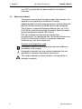
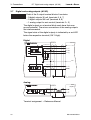
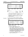
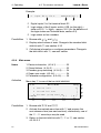
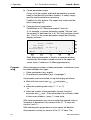
1
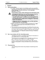
GEL 8230Y005 for Pitch System Control in Wind Power Plants Subject to errors and technical change User Manual Edition: 2003-02 This operating manual is part of the product and must be kept during the product's lifetime and passed together with the product. Issued by: Lenord, Bauer & Co. GmbH Dohlenstrasse 32 46145 Oberhausen • Germany Phone: +49 (0)208 9963-0 • Fax: +49 (0)208 676292 Internet: http://www.lenord.de • E-Mail: [email protected] Doc. no. DS12-8230Y5B10 Lenord + Bauer Table of Contents Table of Contents 1 General ........................................................................................................4 1.1 1.2 1.3 1.4 Safety instructions.........................................................................................4 Use in accordance with the intended purpose ..............................................4 Characteristics ..............................................................................................4 About this manual .........................................................................................6 2 Assembly .....................................................................................................7 2.1 2.2 2.3 2.4 Scope of delivery...........................................................................................7 Control panel cut-out.....................................................................................7 Mounting .......................................................................................................7 Removal........................................................................................................9 3 Connections ..............................................................................................10 3.1 3.2 3.3 3.4 3.5 3.6 3.7 Overall view ................................................................................................10 Voltage supply (V).......................................................................................11 Serial interface (C1) ....................................................................................12 CAN bus (C2)..............................................................................................13 Encoder inputs (Z1/2/3)...............................................................................14 Digital inputs (E1/2/34)................................................................................15 Digital and analog outputs (A1/2/3).............................................................16 4 Operating ...................................................................................................17 4.1 The keyboard ..............................................................................................17 4.2 The Display .................................................................................................18 4.3 The windows and menus ............................................................................19 4.3.1 Menu structure ...............................................................................19 4.3.2 Main window (angles).....................................................................20 4.3.3 Main window (I/O) ..........................................................................21 4.3.4 Main menu......................................................................................22 4.3.5 Encoder simulation .........................................................................27 5 Commissioning.........................................................................................28 5.1 MotionController..........................................................................................28 5.2 Operating system update ............................................................................28 6 Technical data...........................................................................................32 6.1 Dimensional diagram ..................................................................................32 6.2 Module strips...............................................................................................32 6.3 Specifications..............................................................................................33 Index ...............................................................................................................35 DS12-8230Y5B10 3 1 General 1 1.1 1.1 Safety instructions Lenord + Bauer General Safety instructions In order to make it easier for installation and for any possible servicing, the operating software of the MotionController permits online change of device parameters during running operation, therefore Be absolutely certain, when making use of this feature, that no dangerous situations can occur for persons or for the system itself in the system area, by ensuring that − every parameter to be changed is conscientiously and carefully checked for correctness and applicability and for possible effects (above all for changes of velocities) before transmission, − adequate electrical safeguards, such as limit switches and line breakers, are provided. Before carrying out a firmware update (see section 5.2, page 28), switch off the power circuit of the MotionController controlled drive. The assembly and commissioning of the MotionController may only be carried out by trained expert personnel, i.e. persons that are familiar with the safety concepts of electrical and automatic control techniques. (On request, product training is offered by LENORD+BAUER.) 1.2 Use in accordance with the intended purpose The MotionController is intended exclusively for the control of rotor blade drives in a wind power plant. The three axes are equipped with an redundant encoder system to which you can switch over in case of trouble. Control is mainly performed using the specific LB2 protocol. Nominal value preset is always carried out by serial communication. 1.3 Characteristics The following sketch shows the principle of functioning of the control: 4 DS12-8230Y5B10 1.3 Characteristics Encod. group B Encod. group A Lenord + Bauer Blade 1 (Axis 1) Blade 2 (Axis 2) Blade 3 (Axis 3) Blade 1 (Axis 4) Blade 2 (Axis 5) Blade 3 (Axis 6) 1 General SSI encod. 1 SSI encod. 2 SSI encod. 3 SSI encod. 4 SSI encod. 5 SSI encod. 6 Control, nom. value preset RS 232 C v Control Axis 2 v Control Axis 3 v U Blade 1 U Blade 2 U Blade 3 PLC program High PLC Run (E1.1) Control Axis 1 Legend: v = speed, U = (analog) voltage Principle of axis control: v t s t S p e e d p re -c n trl ( n o m . v a lu e g e n e ra to r) D e lta S [D e g re e s ] K sp v v k [D e g re e s /s ] [1 /s ] U v U o [V ] SSI A c t. v a lu e m a n ip u la tio n The scope of the display can be subdivided into two categories: Two so called main windows provide the following information: – Actual positions (angles) of the 3 axes and as well as current data in a lower level (→ section 4.3.2) with the possibility of operating the drive manually Signal conditions on the input and output terminals (→ 4.3.3) Access is made to the following functions via a main menu (→ section 4.3.4): – Device information – Changing the encoder group and encoder simulation – Device parameters with which the MotionController is userspecifically configured Besides the routines for the user interface, the MotionController’s operating system also contains routines for the control and feedback control of 3 drives. These routines can be accessed DS12-8230Y5B10 5 1 General 1.4 About this manual Lenord + Bauer via a PLC program that has been loaded into the MotionController. 1.4 About this manual The present manual gives information about the hardware, the installation and operating of the MotionController. It does not deal with the device parameters, through which the MotionController and the controlled axes can be configured. This is done in a separate Reference Manual (doc. no. DS128230Y5R10), which also provides information about the signal/terminal assignment and the LB2 protocol. PDF files of these manuals may be ordered from LENORD+BAUER. For reading the files, the Acrobat Reader from ADOBE SYSTEMS INCORPORATED is necessary (freeware; download e.g. from www.adobe.com). Symbols and designations used: Paragraphs marked in this way provide important additional information to the subject. Paragraphs marked in this way contain statements that are important for operation according to instructions. This symbol indicates a critical situation or the possibility of damage to property. 6 DS12-8230Y5B10 Lenord + Bauer 2 2.1 2.1 Scope of delivery 2 Assembly Assembly Scope of delivery • MotionController GEL 8230Y005 • Fastening set with 6 nuts, spring washers and plain washers as well as 2 pole shoes • Mating connector set • Cable clamp set • User Manual (this document) • Reference Manual 2.2 Control panel cut-out Æ 4 ,3 165 175 6 x 5 225 112,5 5 5 215 5 Dimensions in mm 2.3 Mounting Make the control panel cut-out in the required position in accordance with the dimensional drawing above Set the device in the cut-out Fasten the device with 6 M4 nuts, spring washers and plain washers Make the electrical connections while observing the following instructions DS12-8230Y5B10 7 2 Assembly 2.3 Mounting Lenord + Bauer Instructions for wiring: To maintain the guaranteed EMC characteristics of the MotionController it is absolutely necessary to take the following steps: Earth the device correctly: short connections via cable lug contacts (6.3 mm) housing/cover → cubicle (wall) as well as housing/cover themselves (use a low inductance earthing strap or flat band conductor) Earth connector cable at the device: uncover the cable screen at a suitable point and clamp it under a cable clip to the cover Use metallic sub D optional mating connectors and clamp the cable screen properly between the connector halves Tighten the fastening screws of the Sub D mating connectors firmly in order to guarantee a secure earth contact (it is recommended that this cable is earthed as well, as shown in the diagram) For good electrical contact and mechanical support of the cable in the terminals, as well as for a safe isolation of the bunched conductors used, provide isolated wire end ferrules in accordance with DIN 46228 part 4 that are captively joined to the conductors with the aid of special crimp pliers. If two or more thinner cables are to be connected to one terminal, the use of twin wire end ferrules is advantageous. The maximum connecting cross-section is 1.5 mm² (incl. ferrule). Use a screwdriver with a blade of 0.4 × 2.5 mm for tightening the terminal screws (M2). Keep all unscreened conductors as short as possible. Lay out the screens with large surfaces at both cable ends The power supply used must correspond to the type of installation class 0 or class 1 in accordance with item B.3 of EN61000-4-5 from 1995. Provide spark suppression for inductive loads (relays, contactors) on the digital outputs (free-wheel diodes or RC-networks in parallel and in direct proximity to the coils) 8 DS12-8230Y5B10 Lenord + Bauer 2.4 Removal 2 Assembly Lay out signal and control cables separately from power cables. If there are potential differences between the machine and electronic earthing connections, or if they may occur, suitable measures have to be provided to ensure that no circulating currents can flow in the cable screen (e.g., lay potential equalization cables with large cross-section or use cable with double screening; in doing so, tie the screen time to one side only in each case). 2.4 Removal For a short-term removal of the MotionController loosen the four knurled thumb screws in the cover (they remain in the top and cannot get lost) and withdraw all connectors After refitting the cover press on the knurled thumb screws and then tighten them up Remove the 6 nuts on the M4 threaded bolts of the MotionController and remove the device DS12-8230Y5B10 9 1 2 3 4 5 6 7 8 9 10 11 1 2 3 4 5 6 7 8 9 10 11 E1 1 E4 E2 1 A2 2 V E3 A3 GND (E4) DE4.1 DE4.2 DE4.3 DE4.4 DE4.5 DE4.6 DE4.7 DE4.8 1 2 3 4 A1 Z2 GND (C) CAN_H CAN_L GND (Z) +5 VDC Out +24 VDC Out SSI-Takt 3/6 /SSI-Takt 3/6 SSI-Data 3 /SSI-Data 3 SSI-Data 6 /SSI-Data 6 Ref_N 3 /Ref_N 3 1 2 3 4 5 6 7 8 9 10 11 TxD RxD Z1 GND (C) GND (Z) +5 VDC Out +24 VDC Out SSI-Takt 2/5 /SSI-Takt 2/5 SSI-Data 2 /SSI-Data 2 SSI-Data 5 /SSI-Data 5 Ref_N 2 /Ref_N 2 3.1 Overall view 1 2 3 4 5 6 7 8 9 1 2 3 4 5 6 7 8 9 1 2 3 4 5 6 7 8 9 1 2 3 4 5 6 7 8 9 9 8 7 6 TxRxTx+ Rx+ 1 2 3 4 5 6 7 8 9 GND (E3) DE3.1 DE3.2 DE3.3 DE3.4 DE3.5 DE3.6 DE3.7 DE3.8 1 2 3 4 5 6 7 8 9 GND (E2) DE2.1 DE2.2 DE2.3 DE2.4 DE2.5 DE2.6 DE2.7 DE2.8 GND (A3) Analog GND AA 3 24 VDC Ext. DA3.1 DA3.2 DA3.3 DA3.4 DA3.5 GND (E1) DE1.1 DE1.2 DE1.3 DE1.4 DE1.5 DE1.6 GND (A2) Analog GND AA 2 24 VDC Ext. DA2.1 DA2.2 DA2.3 DA2.4 DA2.5 3.1 GND (A1) Analog GND AA 1 24 VDC Ext. DA1.1 DA1.2 DA1.3 DA1.4 DA1.5 3 1 2 3 4 5 6 7 10 GND (Z) +5 VDC Out +24 VDC Out SSI-Takt 1/4 /SSI-Takt 1/4 SSI-Data 1 /SSI-Data 1 SSI-Data 4 /SSI-Data 4 Ref_N 1 /Ref_N 1 3 Connections Lenord + Bauer Connections Overall view 1 2 3 4 5 Z3 C2 2 GND (Z) GND 24 VDC 24 VDC (Z) RS 232 C COM 1 C1 5 4 3 2 1 COM 1 RS 422/485 DS12-8230Y5B10 Lenord + Bauer 3.2 Voltage supply (V) 3 Connections Connector coding : 1 2 3 4 5 6 7 8 9 10 11 Z3 C2 E6 E5 E4 Plug E3 A2 A3 1 2 3 4 5 6 7 8 9 V 1 2 3 4 A1 1 2 3 4 5 6 7 8 9 1 2 3 4 5 6 7 8 9 Socket 1 2 3 4 5 6 7 8 9 3.2 Z2 1 2 3 4 5 1 2 3 4 5 6 7 8 1 2 3 4 5 6 7 8 9 E2 1 2 3 4 5 6 7 8 9 10 11 1 2 3 4 5 6 1 2 3 4 5 6 7 E1 Z1 1 2 3 4 5 6 7 8 9 10 11 1 2 3 4 5 6 7 8 9 Voltage supply (V) 1 2 3 4 Both the voltage for the internal circuits of the MotionController as well for the supply of the encoders connected are supplied via terminal block V The encoder supply can be taken via the links as well as from the MotionController supply. 2 4 V D C (Z ) Z1+2+3 1.35 A, 30 V 24V V 4 Power supply 19 - 30 VDC 5V £ 0.6 A E Encoder MotionController G N D (Z ) 1 2 4 V D C 1.35 A, 30 V 3 19 - 30 VDC internal G N D DS12-8230Y5B10 2 11 3 Connections 3.3 3.3 Serial interface (C1) Lenord + Bauer Serial interface (C1) A serial interface is available on connector C1: COM 1. It can either be used as RS 232 C or as RS 422/485. With the RS 422/485 the internal terminating Termination resistor must be switched in at the first and On the last device on the bus with the DIP Off switches next to the connector: both switches in the ON position. The resulting terminating resistance is approx. 125 Ω. 1 2 Plug (25-) 9-pin C1 R d R x D 2 (3) 2 T x D 3 (2) 3 G N D 5 (7) 5 (C) W r Peripherals (PC, etc.) R x D T x D G N D (C) RS 232 C RS 232 C RS 422/485 +U(C) 15k +U(C) 6 R x - 8 T x + 7 T x - 9 T x + + T x - 475 15k (C) R x + 267 2 (C) Peripherals 475 1 (C) (C) (C) G N D (C) R x + R x - 5 G N D (C) RS 422 / RS 485 * Connect pins for a RS 485 The serial interface has the same ground potential as the CAN buses (connector C2). 12 DS12-8230Y5B10 Lenord + Bauer 3.4 3.4 CAN bus (C2) 3 Connections CAN bus (C2) 1 2 3 4 5 One CAN bus interface is available on connector C2: CAN1 . With each of the first and last device on the bus the terminating resistor for the CAN bus must be switched in by the DIP switch next to the connector: switch in position ON. The terminating resistance is approx. 120 Ω. C2 C A N _ H 1 (C) CAN1 2 121 Z3 C2 ON 1 1 2 3 4 5 2 OFF Termination CAN Client C A N 120 C A N _ L 3 G N D (C ) 1 C A N G N D (C) The CAN buses have the same ground potential as the other serial interfaces (connector C1). The CAN bus supports reading and writing of digital CAN Remote I/O modules. A CAN Remote I/O Basic module must be connected to terminal strip C2 to do so. In this module a baud rate of 500 kBit/s and the node address 1 have to be programmed. Reading of the inputs and writing the outputs is performed via LB2 protocol functions (see the Reference Manual). DS12-8230Y5B10 13 3 Connections 3.5 3.5 Encoder inputs (Z1/2/3) Lenord + Bauer Encoder inputs (Z1/2/3) 1 2 3 4 5 6 7 8 9 10 11 Each two SSI encoders can be connected to the terminal strips Z1 – Z3. 5 V and 24 V are available there as supply voltage for the encoders. The maximum current is – for 24 V: 300 mA per encoder – for 5 V: 200 mA per encoder, in total 0.6 A All encoder inputs have the same ground potential. Z1/2/3 (Z) SSI encoder A S S I C lo c k A /B 4 /S S I C lo c k A /B 5 C lo c k S S I-D a ta A 6 D a ta /S S I-D a ta A 7 D a ta S S I-D a ta B 8 /S S I-D a ta B 9 + 5 /2 4 V 0 V C lo c k (Z) 267 2k SSI encoder B 5V6 (Z) A B Z1 1 4 Z2 2 5 Z3 3 6 (V) 24 V DC 5V DC 10 /R e f_ N 11 + 2 4 V D C o u t 3 + 5 V D C o u t 2 G N D (Z ) 1 (Z) C lo c k C lo c k D a ta D a ta max. 0.6 A (Z) (Z) 14 R e f_ N + 5 /2 4 V 0 V DS12-8230Y5B10 Lenord + Bauer 3.6 3.6 Digital inputs (E1/2/34) 3 Connections Digital inputs (E1/2/34) 1 2 3 4 5 6 7 The signal state of each of the 6 (E1) or 8 (E2/3/4) digital inputs is indicated by a green LED below the respective terminal (ON =^ High). E1...4 5V6 x= 2 ... 4 1... 4 2k Control D E x .1 2 D E x .2 3 D E x .3 4 D E x .4 5 D E x .5 6 D E x .6 7 D E x .7 8 D E x .8 9 + 2 4 V G N D (E x ) 1 G N D (Ex) Fixed terminal assignment: DE1.1: PLC RUN (High potential for starting and running an inserted PLC program) DE1.2: /Stop (High potential is conditional for controlling a drive and for calibration procedures) Other terminal assignments → Reference Manual DS12-8230Y5B10 15 3 Connections 3.7 3.7 Digital and analog outputs (A1/2/3) Lenord + Bauer Digital and analog outputs (A1/2/3) 1 2 3 4 5 6 7 8 9 Each of the 3 output terminal blocks A contains: – 3 digital outputs 30 mA (terminals 5, 6, 7) – 2 digital outputs 500 mA (terminals 8, 9) – 1 analog output for axis control (terminals 2 + 3) The digital outputs on a terminal block each have their own ground potential. The minus connections of the analog outputs are interconnected. The signal state of the digital outputs is indicated by a red LED below the respective terminal (ON =^ High). Digital: A1/2/3 2 4 V D C E x t. 4 D A x .1 5 D A x .2 6 D A x .3 7 G N D (A x ) 1 3 x 30 mA (Ax) D A x .4 8 D A x .5 9 Control + 2 4 V G N D 2 x 500 mA (Ax) Analog: A1/2/3 A A 1 /2 /3 10k (Analog A1...3) Drive ampifier 3 2 A n a lo g G N D Terminal assignment → Reference Manual 16 DS12-8230Y5B10 Lenord + Bauer 4 4.1 4.1 The keyboard 4 Operating Operating The keyboard 0 1 / 0 1 1 . A n g l e M A I N 1 : 2 . A n g l e 2 : 3 . A n g l e 3 : W I N [ [ [ [ [ [ [ I / O D O W A ] | B ] | A ] | B ] | A ] | B ] | ] [ U ] F1 F2 F3 F4 7 8 9 0 7 8 7 8 7 8 7 8 7 8 7 8 [ . 5 . 5 . 5 . 5 . 5 . 5 D M E N U 4 ° * 4 ° ÿ | 3 ° | 3 ° | 4 ° | 4 ° | ] F5 M1 M2 M3 M4 Enter 4 3 6 1 2 3 ESC c Function keys (assignment dependent on the current window) d Numerical keys (value input) e Menu keys (assignment dependent on the current window, line oriented) f Delete value input g Cancel input/function; return to next higher menu potential h Confirm input, select/call marked entry (doubly available) i Selection keys (select characteristic of a device parameter) j Scroll keys (move window within the displayable list by one line upwards/downwards) with key repeat (The labeling of the key blocks c and e, as well as the company logo, can be adapted to the application by using customized strips, see section 6.2 on page 32.) DS12-8230Y5B10 17 4 Operating 4.2 4.2 The Display Lenord + Bauer The Display Example: 0 1 / 0 1 1 . A n g l e 1 : 2 . A n g l e 2 : 3 . A n g l e 3 : M A I N W I N D [ A [ B [ A [ B [ A [ B [ I / O ] O W ] ] ] ] ] ] | | | | | | [ U ] 7 8 7 8 7 8 7 8 7 8 7 8 [ . 5 . 5 . 5 . 5 . 5 . 5 M E N U 4 ° * 4 ° ÿ | 3 ° | 3 ° | 4 ° | 4 ° | D ] c Number of the currently shown window with total number of windows (e. g. 01/03 means the first of three possible display windows) d Designation of the menu or function window e Function of the menu key Æ; with the other menu keys the list entries shown on the left can be activated in some winst dows (Ç → 1 list entry etc.) f Each list entry is assigned a definite number; when entering a number a search function will be started, which let you go directly to an entry which is currently not visible, or the entry will be activated if it is already shown in the window g Function of the –…Ð keys (here 'I/O' → ˜: display of the input and output states; 'U' → Ï: scroll 1 window upwards; 'D' → Ð: scroll 1 window downwards) h The blinking cursor marks the entry which will be selected i.e. activated with the confirmation (Enter) keys (see previous section, item h); this is also possible by means of the menu keys Ç…É (in the example above it is Ç) i "Scroll bar": Information (qualitative) about the position of the current window (∗) within the displayable list (|) Further explanations about the various windows you will found in the following descriptions of the menus. 18 DS12-8230Y5B10 Lenord + Bauer 4.3 4.3.1 4.3 The windows and menus 4 Operating The windows and menus Menu structure For the operating and observing of the MotionController various hierarchically classified display windows and setting menus are available. The following diagram gives an overall view of the menu structure. F3 Main window Blade 1...6 (angles) Main window I/O (states) F1 M1 ESC M1 M1 Operating data, Jogging, Reference setting Main menu F5 1 2 F4 ESC 3 M1 4 5 Device info Stored failures Encoder group setting Super user mode Software, Run time Display, Erase Switch over Password Factory defaults Parameters: - reset - create image - compare 2 3 4 ... 7 Encoder simulation Password F5 1 6 Configure parameters F4 8 System parameters Parameters Blade 1 [A] Parameters Blade 3 [B] Parameter setting Parameter setting Parameter setting ESC M1 9 Copy blade parameters Source/target input As the standard display the 'MAIN WINDOW' showing the actual angle positions of the axes (blades) appears after switching on the device; see the next section. In parallel to this there is another 'MAIN WINDOW' that gives information about the signal states of the digital and analog inputs and outputs of the MotionController; see section 4.3.3. DS12-8230Y5B10 19 4 Operating 4.3.2 4.3 The windows and menus Lenord + Bauer Main window (angles) 01/01 1. Blade 1: MAIN WINDOW [A] | [B] | [A] | [B] | [A] | [B] | [I/O] [ U ] 2. Blade 2: 3. Blade 3: F1 F2 F3 F4 MENU 78.54° * 78.54° ÿ| 78.53° | 78.53° | 78.54° | 78.54° | [ D ] M1 M2 M3 M4 F5 Example: 2. Blade 2: [A] | 78.53° | c d e c Letter of the encoder group: A = Encoder 1…3 (here 2), B = Encoder 4…6 (redundant encoder system) d State of motion of the axis: | = standstill, > = forward movement, < = reverse movement, E = error (see Reference Manual) e Actual value of the angle in hundredth of a grade Possibilities 1. Display operating data of the marked axis with [Enter] or [M3] (in the window as shown above) for Blade 2 (Axes 2 and 4): OPERATING STATE: BLADE 2 State: RESET + STOP Encoder/Dir.: [A] | Actual [°]: 78.53 Nominal [°]: Veloc.a/n [°/s]: 0.00 Delta [°]/U [V]: 0.00 [<<] [<] [CAL.] [>] F1 F2 F3 F4 BACK M1 [B] | 78.53 78.54 0.00 0.000 [>>] M2 M3 M4 F5 Explanations of the display: • Veloc.a/n = actual and nominal speed • Delta (= DeltaS) = control deviation = difference between the calculated nominal value from the feedback control and the actual value (see principle of axis control on page 5); if DeltaS exceeds one of the maximum values programmed at the blade parameters ( → Reference Manual) this will be displayed as "DRAG ERROR +" or "DRAG ERROR -" respectively at "State:" • U = control voltage on the analog output (here for Blade 2 at terminal block A2) 20 DS12-8230Y5B10 Lenord + Bauer 4.3 The windows and menus 4 Operating • The drive can be operated manually (jog) or calibrated by means of certain function keys if the corresponding blade parameters have been correctly configured (see Reference Manual): –: Fast jog in reverse direction (<<) —: Slow jog in reverse direction (<) Ï: Fast jog in forward direction (>>) Ð: Slow jog in forward direction (>) ˜: Calibration (see further below) • Æ: Return to standard MAIN WINDOW; also with e 2. Call information about the inputs and outputs of the MotionController with ˜; see next section 3. Call device information or configure parameters: Change to the MAIN MENU with Æ; see section 4.3.4 Calibration With the ˜ key an actual value correction can be activated for a specific blade (encoder group A or B). The value is to be defined at the blade parameters for the concerning axis (see Reference Manual): CALIBRATION: BLADE 2 BACK M1 Calc. zero offset [A]: Calc. zero offset [B]: 0.15° 0.17° M2 M3 Process the calibration? [ YES ] F1 [ NO ] F2 F3 F4 M4 F5 Condition: High potential on terminal E1.2 ("/Stop") 4.3.3 Main window (I/O) Activation Function key ˜ in the standard MAIN WINDOW 01/5 MAIN WINDOW 1. Input E1.7..E1.2: 2. Input E2.9..E2.2: 3. Input E3.9..E3.2: [BLADE] F1 DS12-8230Y5B10 F2 F3 MENU * 100101[25] | | 00010010[12] | | 00000000[00] | [ U ] [ D ] F4 M1 M2 M3 M4 F5 21 4 Operating 4.3 The windows and menus Lenord + Bauer Example: 2. Input E2.9..E2.2: 00010010[12] | c d c Digital inputs 2 to 9 at terminal block E2 e d Logic states of the 8 inputs as bits, LSB (on the right) V state on E2.2; 1 = High V approx. 24 V (for the definition of the logic states see Technical data, section 6.3) e Logic states as hex numbers Possibilities 1. Browse with Í/Ì and Ð/Ï 2. Display actual values of axes: Change to the standard MAIN WINDOW with –; see section 4.3.2 3. Call device information or configure parameters: Change to the MAIN MENU with Æ; see next section 4.3.4 Main menu Items 1. Device information (4.3.4.1) .................... 23 2. Stored failures (4.3.4.2) ........................... 23 3. Encoder group switching (4.3.4.3) ....... 24 4. Super user mode (4.3.4.4)................... 24 5. Parameter configuration (4.3.4.5) ........ 25 Activation Menu key Æ in one of the two MAIN WINDOWS 01/02 MAIN MENU 1. Device info 2. Stored failures 3. Encoder group setting [MAIN] [ U ] F1 Possibilities F2 F3 F4 BACK * ÿ| | | | | [ D ] M1 M2 M3 M4 F5 1. Browse with Í/Ì and Ð/Ï 2. Activate the marked menu item with Î and process the next submenu item (see next sections); alternatively, one of the Ç…É menu keys may be used 3. Return to the MAIN WINDOW with –, Æ or e; see section 4.3.2/4.3.3 22 DS12-8230Y5B10 Lenord + Bauer 4.3 The windows and menus 4 Operating 4.3.4.1 Device information This window informs about the hardware and software versions of the MotionControllers and about the cumulated runtime of the device as shown as an example: DEVICE INFO Hardware STD: Software STD: Runtime: 5.02 SHW: 1.00 SSW: 218:22:04 (c) 2001 by Lenord, Bauer & F1 F2 F3 BACK * | 0.00 | 10.02 | | | Co. GmbH F4 M1 M2 M3 M4 F5 STD = standard, SHW = special hardware, SSW = special (customized) software; the first line ( ) can be written by a PLC program 4.3.4.2 Stored failures This window displays a list with up to 20 failures occurred (most recent on top), e. g . 01/01 STORED FAILURES 1.05 DeltaS > DeltaS max. Count: F1 1 F2 [CLEAR] [ U ] F3 F4 BACK * | | | | | [ D ] M1 M2 M3 M4 F5 ("1.05" → Axis 1, error code 5; see also LB2 function 50h in the Reference Manual) The following failures will be recognized: • DeltaS > DeltaS max. → Drag error exceeds its maximum value when moving in forward direction (see blade parameters in the Reference Manual) • DeltaS < DeltaS min. → Drag error exceeds its maximum value when moving in the reverse direction • General transmission errors and errors in the LB2 protocol; see Reference Manual: LB2 function 50h DS12-8230Y5B10 23 4 Operating 4.3 The windows and menus Lenord + Bauer 4.3.4.3 Encoder group switching ENCODER GROUP SETTING BACK * | Axes 1 - 3: Encoder group [A] | Axes 4 - 6: Encoder group [B] | | | [MAIN] [CHANGE] F1 F2 F3 F4 M1 M2 M3 M4 F5 By means of the Ð key you can change from the default assignment (Axes 1 – 3: group A) to the alternative assignment (Axes 1 – 3: group B) and vice versa. 4.3.4.4 Super user mode LOG IN BACK M1 M2 Enter password: _ M3 [ OK ] F1 F2 F3 F4 M4 F5 For the duration of service, i.e. as long as the device remains switched on, the request for a password to the configuration menu can be suppressed. It may be inquired at authorized persons and, if necessary, be noted down here: When the super user mode is active this is shown by an asterisk in the MAIN MENU window: 4. Super user mode [*] | Hence, for continuously changing in and out of the configuration menu, i.e. while commissioning, the required password does not need to be entered again and again. The other possibility of permanently deactivating the password request by means of a system parameter (under "Configure parameters"/"System parameters"), has the danger that it may be forgotten to cancel this setting afterwards. If this happens there is the possibility of unlimited access to all configuration parameters – even for unauthorized persons. 24 DS12-8230Y5B10 Lenord + Bauer 4.3 The windows and menus 4 Operating The super user mode is also necessary for certain factory default functions in the configuration menu (see next section). The mode is exited when – the device is switched off – the password is input once more. 4.3.4.5 Parameter configuration For the change to the configuration menu a password must first be entered which may be inquired at authorized persons and, if necessary, be noted down here: The password request can be deactivated: a) chronologically unlimited by programming the corresponding system parameter (see Reference Manual) b) for the duration of service (i.e. as long as the device remains switched on) by activating the super user mode (see previous section) 01/03 PARAMETER-CONFIGURATION 1. Factory defaults 2. System parameters 3. Parameters blade 1 [A] [MAIN] [ U ] F1 Factory defaults F2 F3 F4 BACK * ÿ| | | | | [ D ] M1 M2 M3 M4 F5 On delivery, the system and blade parameters are set to certain standard values (defaults), see Reference Manual. The MotionController can be reset to these factory defaults or to another personal configuration at any time. a) Reset parameters There are 2 possibilities: • Basic configuration This menu item is only visible if the super user mode has been activated (see previous section). • Parameter image Before you can use this feature a parameter image must have been created earlier (see next point). DS12-8230Y5B10 25 4 Operating 4.3 The windows and menus Lenord + Bauer b) Create parameter image A copy of all the system and blade parameters is stored safely in the MotionController's memory. A safety inquiry must be confirmed before overwriting. Condition for this feature: The super user mode must be active (see page 24) c) Compare current parameters Possibilities as for "Reset parameters" (point a). If, for example, a system parameter named "Service" with the number 14 has been set to 0 ("No") but has been stored as 1 ("Yes") in the recent parameter image the following display is shown: 01/02 COMPARE RESULT IMAGE Group: SYSTEM Sub group: Parameter: 14 Service Value/Default: 0 [MAIN] [] [] [ U ] F1 F2 F3 F4 BACK * | | | 1 | | [ D ] M1 M2 M3 M4 F5 Each differing parameter is listed in a separate window indicated by the window number shown in the upper left corner (here: 2 windows =^ 2 differing parameters). Programming When changing a system or blade parameter, a distinction must be made between two types: • Value parameters (e.g. angles) • Characteristic parameters (e.g. “Languages”) A parameter can be activated for input/changing as follows: Mark with the cursor keys (Í, Ì) and press Î or press the matching menu key (Ç, È or É) or Enter the number of the parameter (search function), terminate with Î and – if the parameter has not been visible in the current window – press Î once more. With value parameters you can now enter the desired value or increment or decrement it by means of the Ê, Ë keys and confirm it with Î. With characteristic parameters you can select the desired characteristic (variant) by means of the Ê, Ë keys. The 26 DS12-8230Y5B10 Lenord + Bauer 4.3 The windows and menus 4 Operating possible variants are numbered starting from 0, in addition to the text shown in the display. The bottom display line shows the Min/Max values of the parameter. After finishing the input/selection with Î, i.e. when a parameter has been changed, the parameter values will be stored safely in the flash memory as soon as you return to the main menu; the bottom display line informs about that. Do not switch off the device during this procedure; otherwise all parameter settings will be lost! For the description of the system and blade parameters see the Reference Manual. 4.3.5 Encoder simulation When entering a specific password in this window the encoder simulation can be activated or deactivated respectively. The password may be inquired at authorized persons and, if necessary, be noted down here: When the encoder simulation is active this is shown by an asterisk in the MAIN MENU window: 6. Encoder simulation [*] | Encoder simulation has been designed as commissioning aid presenting the possibility of testing the MotionController without axes being connected. Manual movements (manual keys, jog mode) or positioning procedures (also via LB2 protocol, e.g. by the master computer) are processed with simulated actual value feedback. The analog outputs will output the normal i.e. calculated voltage for controlling the servo amplifiers. DS12-8230Y5B10 27 5 Commissioning 5 5.1 5.1 MotionController Lenord + Bauer Commissioning MotionController Before switching on the MotionController for the first time it must be ensured that the connection E1.1 (PLC Run) is at Low potential in order to prevent a stored PLC program from being started immediately. After mounting and making all the necessary electrical connections, the MotionController can be switched on by applying the supply voltage to the terminal block V (terminals 2 and 3). After a short initialisation period the MotionController answers with the following display: 01/01 1. Blade 1: 2. Blade 2: 3. Blade 3: F1 F2 MAIN WINDOW [A] | [B] | [A] | [B] | [A] | [B] | [I/O] [ U ] F3 F4 MENU 78.54° * 78.54° ÿ| 78.53° | 78.53° | 78.54° | 78.54° | [ D ] M1 M2 M3 M4 F5 Individual adaptations for the MotionController and the axes to be controlled can now be carried out. The configuration parameters listed in the Reference Manual serve this purpose. After the setting of all axis-dependent control parameters the drives can be operated manually via the keyboard (see section 4.3.2, page 20). If the MotionController already contains a PLC program extension, this may now be started with High on terminal E1.1. 5.2 Operating system update Before running the update procedure de-energize all power circuits of the drives controlled by the MotionController. If the MotionController needs to be provided with a new operating system software use the utility 'LingiMon' supplied for this purpose. It can be ordered from LENORD+BAUER as freeware. For the installation of LingiMon run the program LingiMonSetup.exe. The utility will now be installed on the hard disc in a Windows-specific procedure (the directories can still be adapted to user needs). 28 DS12-8230Y5B10 Lenord + Bauer 5.2 Operating system update 5 Commissioning If LingiMon has already been installed, the "old“ version will first be deinstalled by the installation routine: For a new installation following that LingiMon Setup must be executed once again. After the installation, start the program either via the Windows Start menu or with a double click with the left hand mouse button on a binary file with the extension '.h86' or '.b86' in the Windows Explorer. By means of a null modem cable make a connection between the PC (RS232 C: COM 1/2) and the MotionController (connector C1). In the program select the COM port used (set via the connector symbol). Per default the transmission rate is set to 57,600 baud. If problems occur during data transfers, reduce the transmission rate in steps down to the minimum value of 9,600 baud (to be set via the connector symbol). Start of LingiMon with selected binary file (.h86): The status bar provides information about the selected COM port (COM 1), the transmission rate (57600 baud) and the type of the file loaded (operating system). Before transmission of the data in the flash memory of the device this is first of all deleted. In general it is sufficient to DS12-8230Y5B10 29 5 Commissioning 5.2 Operating system update Lenord + Bauer delete only the operating system area – as given as a default by the program. In this way, an existing PLC program and the system parameter settings are preserved. The other option can be released in the 'Download options' (click on the connector symbol). During the transmission of data do not change to another application – the transmission window must keep the focus; the procedure, then, can be followed on the progression bar shown. Otherwise Windows-specific errors can occur during the transmission procedure that cause the MotionController to permanently "get lost". In such a case repeat the transmission. After confirming with OK the program requests the resetting of the device. Switch the MotionController off Hold the miniature key inside the housing pressed down with a non-metal stick (e.g. a match), as shown in the following illustration, and switch on the device again. Z1 E 5V 24V C C A A B B N N Z2 E 5V 24V C C A A B Release the key The MotionController is now prepared for the download (only one or more lines can be recognized in the display). After confirmation with OK the transmission procedure begins (approx. 250 Kbytes): 30 DS12-8230Y5B10 Lenord + Bauer 5.2 Operating system update 5 Commissioning At the end of the (successful) transmission the MotionController switches to normal operation. If this does not happen, repeat the transmission procedure, with a reduced transmission rate perhaps. The contents of the complete flash memory or only a part of it can also be uploaded, i.e. read out and saved in a file with the extension '.b86'. This can then be written back again at any time – as explained above (backup function). The name of the file is automatically created from the selected option, but can be altered as required. The memory area to be uploaded is to be defined in the 'Upload options' (click on the connector symbol). Via the magnifying glass symbol you can compare the data shown in the window with those in the MotionController. For this purpose an upload procedure is run automatically. DS12-8230Y5B10 31 6 Technical data 6 6.1 6.1 Dimensional diagram Lenord + Bauer Technical data Dimensional diagram 112.5 7.5 49.4 67.5 19 112.5 16.8 208 20.8 55 23.2 22.8 160 23 190 158 175 21 M4 7.5 240 7 8 9 4 3 6 1 2 3 0 23 17 21 Enter ESC Dimensions in mm 6.2 Module strips 170 x 19 mm (W x H) M1 M2 M3 M4 42 x 39 mm (W x H) F1 F2 F3 F4 F5 170 x 19 mm (W x H) 32 DS12-8230Y5B10 Lenord + Bauer 6.3 6.3 Specifications 6 Technical data Specifications Supply Voltage Max. load – Controller – encoders 19 … 30 V DC (Controller und optional encoders) 1A 1 A (24 V) / 0.6 A (5 V) µProcessor Memory: RAM Flash non-volatile RAM Control sampling time C167 Serial (PC communication/programming) CAN bus – protocol – min. contr. sampling time necessary – input objects (PDOs) – output objects (PDOs) – SDO objects Fieldbus 1; RS 232 C or RS 422/485 (baud rate adjustable) 1 (CAN 1) CANopen, CAN Link, LB2 2 ms Act. value inputs Number 3 (SSI); 5 / 24 V, clock frequency 100 kHz Inputs Digital 30; 24 V, status indicated by green LEDs; Low = 0…+5 V, High = +15…30 V Control Interfaces – logic potential Outputs Digital Analog Memory range – program – data – data backup DS12-8230Y5B10 1 Mbytes 1 Mbytes 8 Kbytes 6 ms 4, each 64 bit data width 4, each 64 bit data width max. 64 1 extension slot for PROFIBUS-DP, InterBus-S, DeviceNet (others on request) 9 × 30 mA, 6 × 500 mA 24 V, status indicated by red LEDs 3 ±10 V, 10 mA, 2 mV resolution 256 Kbytes 128 Kbytes 128 Kbytes 33 6 Technical data 6.3 Specifications – non-volatile RAM Programming Lenord + Bauer 4 Kbytes Development environment CoDeSys in accordance with IEC 61131-3 Environment (application classes KWF according to DIN 40040) Working temperature 0 °C to +50 °C Operating temperature -20 °C to +50 °C Storage temperature -20 °C to +70 °C Relative humidity ≤ 95%, non-condensing EMC (by observance of the wiring information, see page 8) Emitted interference DIN-EN 50081-1 Interference immunity DIN-EN 50082-1 in accordance with EU Guideline Y sign EMC 89/336/EEC Type LCD, 240 × 64 pixel, LED illumination Visible area 133 mm × 39 mm Enclosure Material Front panel Weight Sheet steel, galvanized Aluminum with edge protection approx. 1.7 kg Protective class Front side Rear side IP 65 IP 20 Display Maintenance The device is maintenance-free. Use a moistened cloth for cleaning the front panel; do not use solvents. 34 DS12-8230Y5B10 Index Lenord + Bauer Index .b86 29, 31 .h86 29 /Stop 15, 21 Acrobat Reader 6 Actual value correction 21 Adaptations 28 Adobe 6 Analog outputs 16 angle position 19 Axis control (principle) 5 Backup 31 Binary file 29 Cable clamp set 7 Cable screen 8 Calibration 21 CAN bus 13 CAN1 13 CAN Link 33 CAN Remote I/O 13 CANopen 33 Circulating currents 9 COM port 29 Commissioning 24 Company logo 17 Configuration 25 Configuration menu 24, 25 Configuration parameters 24 Connections 10 Connector cable 8 Connector coding 11 control deviation 20 Control panel cutout 7 Control sampling time 33 control voltage 20 Dangerous situation 4 DeltaS 20 Device information 21, 22, 23 Digital inputs 15 Digital outputs 16 Dimensional diagram 32 DIP switch 12, 13 Display windows 19 Download 30 Drag error 20, 23 Earthing strap 8 EMC 8, 34 Encoder 11 inputs 14 DS12-8230Y5B10 supply voltage 14 Encoder group 5, 21 switching 24 Encoder simulation 5, 27 Error code 23 Extesion slot 33 Factory defaults 25 Failures 23 Fieldbus 33 Firmware 4 Flash memory 27, 29 Flat band conductor 8 Function keys 17 Hardware version 23 Inbetriebnahme 28 Inputs digital 15 encoder 14 Internal circuits 11 LB2 protocol 4, 6, 13, 23 LED 15, 16 LingiMon 28 List entry 18 Logic state 22 Main menu 5, 22 Main window angles 20 I/O 21 Manual information 6 Manual operation 21 Memory Controller 33 PLC 33 Menu keys 17, 18 Menu level 17 Menu structure 19 Miniature key 30 Module strips 32 MotionController operating system 28 switch on 28 Null modem cable 29 Operating data 20 Operating system 5 update 28 Outputs analog 16 digital 16 Parameter characteristic 26 configuration 28 device 4 value 26 Parameter configuration 25 Parameter image 25 Password 25, 27 request 24 Password request 25 PDF file 6 PDO 33 PLC start input (Run) 28 PLC program 6, 28, 30 start 28 PLC RUN 15 Potential differences 9 Reference manual 6 Runtime 23 Scope of delivery 7 Scope of display 5 Scroll bar 18 Scroll keys 17 SDO 33 Search function 18, 26 Selection keys 17 Serial interface 12 Service 24, 25 Setting menus 19 Signal states 19 Software version 23 Specifications 33 SSI encoder 14 State of motion 20 Stop input 15 Stored failures 23 Strip 17 Sub D connector 8 Super user mode 24, 25 Technical data 32 Terminating resistor 12, 13 Transmission error 23 Transmission procedure 30 Transmission rate 29 Upload 31 Variant 26 Voltage supply 11 Wire end ferrules 8 Wiring 8 Zero offset 21 35 Your dealer: Please contact your dealer if you have technical questions. A current overall view of dealers can be found on our website www.lenord.de.