1
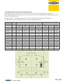
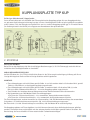
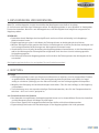
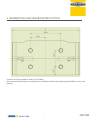
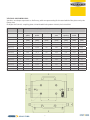
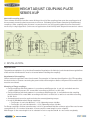
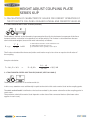
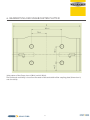
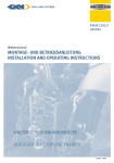
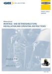
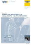
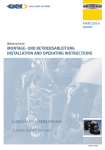
ATASC1207.0
400009
Walterscheid
MONTAGE- UND BETRIEBSANLEITUNG
INSTALLATION AND OPERATING INSTRUCTIONS
> KUPPLUNGSPLATTE TYP KUP
> HEIGHT ADJUST COUPLING PLATE
SERIES KUP
KUPPLUNGSPLATTE TYP KUP
1. BEZEICHNUNGEN, ABMESSUNGEN UND KENNWERTE:
BAUARTGENEHMIGUNG: EG:
e1*2009/144*0480
ABG: M 10036
Kennwerte:
• Zul. D-Wert: 89,3 kN
• Stützlast: 2.000 daN (kg), ohne Geschwindigkeitsbegrenzung
• Stützlast: 2.800 daN (kg), Höchstgeschwindigkeit
40 km/h
(beachten Sie hierzu den Abschnitt „zulässiger Stützabstand“)
Es sind der D-Wert und die Stützlast der angebauten Kupplung zu beachten. Der jeweils niedrigere Wert ist
gültig.
Sofern nach geltenden nationalen Zulassungsbestimmungen des jeweiligen Anwenderlandes für die Inanspruchnahme dieser Kennwerte zusätzliche amtliche Genehmigungen erforderlich wären, sind diese zu
be-antragen.
Die Kupplungsplatten werden im Geltungsbereich der StVZO auch als Anhängeböcke bezeichnet.
Die Kupplungsplatten können ausschließlich in Anhängeböcken mit schnellhöhen-verstellbaren Rastschienen wie z. B. KU 301X, ABG-Nr. M 9872 bzw. EG-Nr. e1*89/173/IV-0389 betrieben werden.
Hier sind der D-Wert und die zulässige Stützlast des Anhängebocks zu beachten. Der jeweils niedrigere
Wert ist gültig.
Beim Einsatz oberhalb der Zapfwelle sind die Angaben des Fahrzeugherstellers hinsichtlich der Stützlasten
zu beachten.
Zugösen:
Bitte beachten Sie die Bedienungsanleitung der angebauten Kupplung.
Die Kupplungsplatten können in verschiedenen Anbaumaßen und verschiedenen Aufnahmebohrungen
ge-mäß nachfolgenden Tabellen geliefert werden. Sie sind vorbereitet zum Anbau von Anhängekupplungen
oder vergleichbaren Verbindungseinrichtungen mit unterschiedenen Flanschmaßen. Die Flanschgrößen entsprechen den Klassen gemäß RiLi 94/20/EG. Die Größe 45 ist eine Kombination aus 4 und 5, siehe Ta-belle.
Flanschgröße
Plattenmaß A x H
Lochbild a x b
Loch-Ø c
Flanschmaße
Breite x Höhe
[mm]
[mm]
[mm]
[mm]
4
Maß A x 170
140 x 80
M16
180 x 120
45
Maß A x 170
140 x 80
M20
180 x 120
5
Maß A x 200
160 x 100
21
200 x 140
2
AUSFÜHRUNGSBEZEICHNUNGEN UND ABMESSUNGEN :
Die Kupplungsplatten werden für verschiedene Anhängebock-Rastschienenbreiten hergestellt.
Die Ausführungsbezeichnungen heißen stets: KuP xxx-y, wobei xxx für die Breite der Kupplungsplatte und y
für die Flanschgröße steht.
Beispiel: KuP322-45: Kupplungsplatte 322 breit mit Lochbild 140x80, Gewindebohrung M20
Im Folgenden die Abmessungen der Platten und der zu gehörigen Böcke:
Ausführungs- Lf. Nr.
bezeichnung
Anhängebock (Kupplungsplatte)
Anhängebock Führungsschine
Breite
Dicke
Bolzen
Fläche
Maß A
Maß B
Maß C
Maß D
Breite
Nut
Bohrung
[mm]
[mm]
[mm]
[mm]
[mm]
[mm]
[mm]
KuP389-y
1
389
31,7
25
349
390
32,0
25,5
KuP335-y
2
335
29,7
22
300
336
30,0
23
KuP333-y
3
333,5
37,65
25
280
334,5
38,0
25,5
KuP329/30-y
4
329
30
20
279
330
31,0
23
KuP329-y
5
329
31,7
25
279
330
32,0
25,5
KuP322-y
6
322
29,7
22
287
323
30,0
23
KuP320-y
7
320
37,65
25
280
321
38,0
25,5
KuP314-y
8
314
30
20
284
315
31,0
23
KuP311-y
9
311
30,3
22
281
312
30,3
23
KuP310-y
10
310
37,65
25
276
311
38,0
25,5
KuP309-y
11
309
29,7
22
274
310
20,0
23
KuP306-y
12
306
37,65
25
266
307
38,0
25,5
3
KUPPLUNGSPLATTE TYP KUP
Zulässiger Stützabstand / Kuppelpunkt:
Der maximale Abstand von der Mitte der Führungsleiste der Kupplungsplatte bis zum Kuppelpunkt der
an-gebauten Verbindungseinrichtung beträgt 222 mm. Nachfolgende Grafik zeigt beispielhaft ausgeführte An-bauten. Falls der Stützabstand größer 222 mm ist, muß die Kupplungsplatte ggf. in Einzelabnahme
(im Geltungsbereich der StVZO) mit angepassten Kennwerten überprüft werden.
2. MONTAGE
WICHTIGER HINWEIS:
Beim Einbau der Kupplung sind die einschlägigen Bestimmungen (z. B. UVV Fahrzeuge) sowie die Anbaurichtlinien der Fahrzeughersteller zu beachten!
ANBAU DER ANHÄNGEKUPPLUNG:
Auf die Pflichten des § 13 FZV hinsichtlich der Daten in der Zulassungsbescheinigung in Bezug auf die zulässige Anhängelast sowie auf die zulässige Stützlast wird hingewiesen.
MONTAGE:
• Flanschkupplungen mit Lochbildern gemäß Größe -4 und -45 werden mittels 4 Schrauben M 16 gemäß
DIN 933 oder DIN 912 an der Kupplungsplatte angeschraubt.
• Flanschkupplungen mit Lochbildern gemäß Größe -5 werden mittels 4 Schrauben DIN 933 oder
DIN 912 sowie 4 Muttern M20 DIN 934 – 10 an der Kupplungsplatte angeschraubt.
• Zum Erzielen des korrekten Anzugsdrehmoment einen Drehmomentenschlüssel verwenden.
• Bei Verwendung von GKN Walterscheid Flanschkupplungen:
•Für Flansche -4 Schrauben M16x45 – 10.9 verwenden, Anzugsdrehmoment 280 Nm.
•Für Flansche -45 Schrauben M20x50 – 10.9 verwenden, Anzugsdrehmoment 550 Nm.
Für Flanschkupplungen anderer Hersteller ist sicherzustellen, daß die Mindestklemmlänge der verwendeten
Schrauben 1,2 x Nenndurchmesser entspricht. Ggf. ist die Schraubenlänge anzupassen.
Bei Flanschen -5 ist die Schraubenlänge so zu wählen, daß die Mutter M 20 vollständig trägt.
Die Kupplungsplatten mit Flanschgrößen 4 und 45 können alternativ ohne Aufnahmebohrungen geliefert
werden. Sie werden dann nachträglich mit den entsprechenden Lochbildern gemäß Punkt 6 versehen. Die
Bearbeitung darf ausschließlich in einer autorisierten Fachwerkstatt erfolgen.
4
3. BESCHREIBUNG UND BEDIENUNG:
Beim Ein- und Auskuppeln sind die Vorschriften der Berufsgenossenschaft zu beachten.
Es darf niemand zwischen den Fahrzeugen stehen. Die Kupplungsplatte ist ausschließlich im Verriegelten
Zustand zu betreiben. Beim Ein- und Auskuppeln muss die Anhängedeichsel möglichst waagerecht zur
Kupplung stehen.
BEDIENUNG:
• Rastbolzen durch Betätigen der Handgriffe nach rechts und links vollständig in die Kupplungsplatte einrasten lassen.
• Kupplungsplatte von oben in die Nuten der Führungsleisten am Anhängebock einschieben.
• Mit dem Handgriff auf die gewünschte Position im Anhängebock schieben, Rastbolzen entriegeln und
in die entsprechenden Rastbohrungen am Anhängebock einrasten lassen.
• Grundsätzlich ist nach jeder Verstellung der Kupplungsplatte zu kontrollieren, ob die Rastbolzen korrekt in den Bohrungen der Führungsleisten eingerastet sind. Nur dann ist eine ordnungsgemäße
Verriegelung gegeben
• Die Führungsschiene der Kupplungsplatte darf nicht über die Führungsnuten des Anhängebocks herausstehen.
Die Kupplungsplatte darf nur im verriegelten Zustand betrieben werden!
4. WARTUNG
4.1 Pflege
• Die Kupplungsplatte ist stets von Schmutz und Korrosion zu befreien, um eine einwandfreie Funktion
zu gewährleisten. Alle beweglichen Teile der Kupplungsplatte (Rastbolzen und Griffe) sind regelmäßig zu schmieren (abhängig von der Gebrauchsdauer) und auf Leichtgängigkeit zu überprüfen.
• Möglichst die Reinigung mit Hochdruckreinigern vermeiden. Falls dies doch erfolgt, ist die Kupplung
nachzufetten.
• Zur Schmierung muss ein wasserbeständiges Fett benutzt werden, dass für den Temperaturbereich
zwischen –40°C und +120°C geeignet ist.
4.2 Sicherheitstechnische Hinweise
• Der Anwender ist verpflichtet, die Kupplungsplatte immer nur in einwandfreiem Zustand zu betreiben
und die Benutzung durch Unbefugte zu untersagen.
• Die auf dem Typenschild angegebenen Belastungen dürfen nicht überschritten werden.
• Eigenmächtige Umbauten und Veränderungen an der Kupplungsplatte sind nicht gestattet.
5
KUPPLUNGSPLATTE TYP KUP
5. BESTIMMUNG DER KENNWERTE ZUM VORSCHRIFTSMÄSSIGEN
BETRIEB DER KUPPLUNGSKUGEL AN LOF-FAHRZEUGEN
5.1 ZUGFAHRZEUG MIT MEHRACHSANHÄNGER (D-WERT)
Als D-Wert ist die theoretische Vergleichskraft für die Deichselkraft zwischen Zugfahrzeug und Anhänger definiert. Der D-Wert errechnet sich aus den beiden zulässigen Gesamtgewichten (Zugfahrzeug und Mehrachsanhänger) wie folgt:
T
D=gx
•
R
T+R
in kN
T: Gesamtmasse des Fahrzeuges in t
R: Gesamtmasse des Anhängers in t
g: Erdbeschleunigung: 9,81 m/s2
Der errechnete D-Wert für die Zugkombination darf kleiner oder gleich dem D-Wert der Verbindungsein
-richtung sein.
Berechnungsbeispiel:
T = 14 t; R = 26 t
–>
D = 9,81 x
14
•
26
14 + 26
= 89,3 kN
5.2 ZUGFAHRZEUG MIT STARRDEICHSELANHÄNGER (D-WERT, STÜTZLAST S)
Der D-Wert ist wie unter 5.1 zu berechnen
Hier ist zusätzlich die zulässige statische Stützlast am Kuppelpunkt zu beachten.
Als statische Stützlast S ist der Massenanteil definiert, der im statischen Zustand durch den Zentralachsanhänger am Kuppelpunkt übertragen wird.
Die maximal zulässige Stützlast richtet sich nach den Angaben der kombinierten Einrichtungen
(es gilt der jeweils kleinere Wert).
6
6. BEARBEITUNG DER UNGEBOHRTEN PLATTEN
Lochbild der Flanschgrößen 4 (M16) und 45 (M20).
Die horizontale Bearbeitung ist ausgehend von der Mitte der Breite der Kupplungsplatte (Maß A, siehe auch
Tabelle).
7
HEIGHT ADJUST COUPLING PLATE
SERIES KUP
1. OPERATING RANGE, CHARACTERISTIC VALUES AND TYPE APPROVALS:
TYPE APPROVALS: EC APPROVAL NO.: E1*2009/144*0480
GERMAN APPROVAL (ABG) NO.: M 10036
Charcteristic values:
• admissible D value: 89.3 kN
• admissible vertical load: 2000 daN (kg) at
speed > 40 km/h
• admissible vertical load: 2800 daN (kg) at speed ≤ 40 km/h
(please consider the section „admissible coupling point“)
Attention must be paid to the D value and the maximum vertical load of the mounted coupling in this context. The lower value applies in each case.
If the valid national approval regulations of the respective country of use require additional official approvals for using these parameters, such approvals must be applied for.
KuP coupling plates is only appropriate for use in hitch frames,, e.g. KU 355, F 4267 or e1-0108. Attention
must be paid to the D value and the maximum vertical load of the hitch frame in this context. The lower
value applies in each case.
For use above the PTO, pay attention to the vehicle manufacturer‘s data regarding vertical loads.
Trailer rings:
Please consider the operating instructions of the mounted coupling.
The coupling plates can be supplied in different mounting dimensions and different mounting holes in
accor-dance with the following tables. They are ready to mount trailers coupling or other connecting devices
with different flange sizes. The flange sizes correspond to the classes defined in EC directive 94/20/EG.
Size 45 is a combination of 4 and 5, see table.
Flange size
4
Plate size A x H
Hole pattern a x b
Hole-Ø c
Flange size
width x height
[mm]
[mm]
[mm]
[mm]
Maß A x 170
140 x 80
M16
180 x 120
45
Maß A x 170
140 x 80
M20
180 x 120
5
Maß A x 200
160 x 100
21
200 x 140
8
VERSIONS AND DIMENSIONS:
Versions are always expressed as: KuP xxx-y, with xxx representing for the total width of the plate and y the
flange size.
Example: KuP322-45: coupling plate 322 wide with hole pattern 140x80, hole size M20
Versions
No.
Coupling plate (slider)
Hitch frame
Total
width
Guide
width
Pin dia.
Mounting
area
(dim. A)
(dim. B)
(dim. C)
(dim. D)
[mm]
[mm]
[mm]
Guide
spacing
Guide
width
Hole dia.
[mm]
[mm]
[mm]
[mm]
KuP389-y
1
389
31,7
25
349
390
32,0
25,5
KuP335-y
2
335
29,7
22
300
336
30,0
23
KuP333-y
3
333,5
37,65
25
280
334,5
38,0
25,5
KuP329/30-y
4
329
30
20
279
330
31,0
23
KuP329-y
5
329
31,7
25
279
330
32,0
25,5
KuP322-y
6
322
29,7
22
287
323
30,0
23
KuP320-y
7
320
37,65
25
280
321
38,0
25,5
KuP314-y
8
314
30
20
284
315
31,0
23
KuP311-y
9
311
30,3
22
281
312
30,3
23
KuP310-y
10
310
37,65
25
276
311
38,0
25,5
KuP309-y
11
309
29,7
22
274
310
20,0
23
KuP306-y
12
306
37,65
25
266
307
38,0
25,5
9
HEIGHT ADJUST COUPLING PLATE
SERIES KUP
Admissible coupling point:
The maximum distance from the center of the guide rail of the coupling plate up to the coupling point of
the mounted connecting device amounts to 222 mm. Following figure shows exemplarily implemented
couplings. If the coupling point distance is more than 222 mm, the coupling plate must be examined if
necessary in single approvals (in the area of application of the StVZO) with adapted characteristic values.
2. INSTALLATION:
Important note:
The pertinent regulations (e.g. Accident Prevention Regulations for Vehicles) and the attachment guidelines
of the vehicle manufacturers must be observed when installing the coupling!
Attachment of the coupling:
Official national regulations must be observed. For example: in Germany the obligations §13 FZV regarding
the data in the car license concerning the permissible trailer weight as well as the permissible vertical load
must be considered.
Mounting of flange couplings:
• Flange couplings with hole patterns in accordance with flange size -4 and -45 are bolted onto the
coupling plate by means of 4 screws M16 according to ISO 4017 or ISO 4762.
• Flange couplings with hole patterns in accordance with flange size -5 are bolted onto the coupling
plate by means of 4 screws M20 according to ISO 4017 or ISO 4762 as well as 4 nuts M20 according
to ISO 4032.
• A torque wrench must be used to obtain the correct tightening torque.
• In use of GKN Walterscheid flange couplings:
• For flanges -4 use bolts M16x45 – 10.9, tightening torque 280 Nm.
• For flanges -45 use bolts M20x50 – 10.9, tightening torque 550 Nm.
For flange couplings of other manufacturers it is to be guaranteed that the minimum grip of the used screws
corresponds to 1.2 x nominal diameters. If necessary the screw length is to be adapted.
With flanges -5 the screw length is to be selected in such a way that the M 20 nut carries completely.
10
The coupling plates with flange sizes 4 and 45 can be supplied alternatively without mounting holes. They
can be provided with the appropriate hole patterns in accordance with point 6. The machining may take
place exclusively in an authorized framework place.
3. OPERATION:
The pertinent safety regulations must be observed when coupling and uncoupling.
No one may stand between the vehicles. The coupling plate may only be operated in locked condition.
OPERATION:
• Push slider from above into the slots of the guide rails of the coupling frame.
• Shift locking pins right and left into the slider by use of the handle.
• Move to the preferred height position, release handle and engage automatically into the appropriate
holes of the coupling frame.
• In general it is to be checked after each adjustment of the slider whether the locking pins are properly
engaged in the holes of the guide rails. Only then the correct locking state is given.
• The guide of the slider must not project beyond the guide slots of the frame, both above and down.
4. MAINTENANCE:
4.1 Care
• Any dirt and corrosion must always be cleaned off the coupling plate in order to guarantee correct
operation. All moving parts of the coupling must be lubricated regularly (depending on the length of
(use)and checked for easy movement.
• If possible, avoid cleaning with a pressure washer. If this is unavoidable, re-grease the coupling.
• In the event of lubrication, remove the old grease and lubricate the coupling plate with fresh grease.
The coupling plate must be lubricated with water-resistant grease suitable for the temperature range
from -40 °C to +120 °C.
4.2 SAFETY NOTES
• The user is obliged to always operate the coupling in perfect condition and to forbid its use by unauthorised persons.
• The loads indicated on the type plate may not be exceeded.
• Unauthorised conversion or modification of the coupling is not permitted.
11
HEIGHT ADJUST COUPLING PLATE
SERIES KUP
5. CALCULATION OF CHARACTERISTIC VALUES FOR CORRECT OPERATION OF
THE PITON-TYPE COU-PLING ON AGRICULTURAL AND FORESTRY VEHICLES
5.1 TRACTOR WITH MULTI-AXLE TRAILER (D VALUE)
The D value is defined as the theoretical representative force for the horizontal component of the force
between vehicle and trailer in longitudinal axis of the vehicle. The D value is calculated from the two
admissible total weights (tractor and multi-axle trailer) as follows:
T
D=gx
•
R
T+R
in kN
T: admissible total mass of the vehicle in tons
R: admissible towed mass in tons
g: acceleration due to gravity = 9.81 m/s2
The D value calculated for the tractor/trailer combination may be less than or equal to the D value of
the coupling.
Sample calculation:
T = 14 t; R = 26 t
–>
D = 9,81 x
14
•
26
14 + 26
= 89,3 kN
5.2 TRACTOR WITH CENTRE-AXLE TRAILER (D VALUE, VERTICAL LOAD S)
The D value is calculated in accordance with 5.1.
In this case, attention must additionally be paid to the admissible static vertical load at the coupling point.
The static vertical load S is defined as the load transmitted by the centre-axle trailer at the coupling point in
static state.
The maximum admissible vertical load depends on the data of the connected devices (the lower value
applies in each case).
12
6. BEARBEITUNG DER UNGEBOHRTEN PLATTEN
Hole pattern of the flange sizes 4 (M16) and 45 (M20).
The horizontal machining is based on the center of the total width of the coupling plate (dimension A,
see also table).
13
GKN WALTERSCHEID GMBH
Hauptstraße 150
D-53797 Lohmar
Tel: +49 2246 12-0
Fax: +49 2246 12-3501
[email protected]
www.gkn-walterscheid.de
Walterscheid
MONTAGE- UND BETRIEBSANLEITUNG
KUPPLUNGSPLATTE TYP KUP
INSTALLATION AND OPERATING INSTRUCTIONS
HEIGHT ADJUST COUPLING PLATE SERIES KUP
Walterscheid
das Original