1
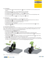
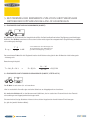
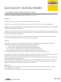
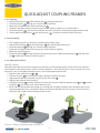
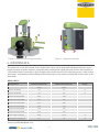
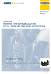
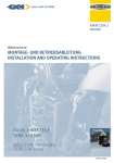
ATASC1202.0
400004
Walterscheid
MONTAGE- UND BETRIEBSANLEITUNG
INSTALLATION AND OPERATING INSTRUCTIONS
> WALTERSCHEID ANHÄNGEBÖCKE
> QUICK-ADJUST COUPLING FRAMES
WALTERSCHEID ANHÄNGEBÖCKE
1. BEZEICHNUNGEN UND TECHNISCHE DATEN:
Ausführungsbezeichnungen, Bauartgenehmigung und Kennwerte: siehe Anhang 1
Verwendungsbereich:
Zum Einsatz an land- oder forstwirtschaftliche Zugmaschinen.
Der Anhängebock ist mit Verbindungseinrichtungen gemäß Anhang 1 zu betreiben.
Hier sind der D-Wert und die zulässige Stützlast der Verbindungseinrichtung zu beachten. Der je-weils
niedrigere Wert ist gültig.
Beim Einsatz von anderen Verbindungseinrichtungen sind die wirksamen Stützlängen zu beachten. Sie
müssen kleiner oder gleich denen der in Anhang 1 angegebenen Komponenten sein.
Sofern nach geltenden nationalen Zulassungsbestimmungen des jeweiligen Anwenderlandes für die Inanspruchnahme der Kennwerte gemäß Anhang 1 zusätzliche amtliche Genehmigungen erforderlich wären,
sind diese zu beantragen.
Ausführungsbezeichnungen:
Anhängeböcke können in verschiedenen Ausführungen gebaut werden. Bei GKN Walterscheid werden folgende Kennbuchstaben der Bock-Type in den Ausführungsbezeichnungen angehängt:
• L: „langer“ Bock, i. d. R. für den deutschen Markt, nur lange Rastschiene.
• F: „französischer“ Bock, d. h. mit fest eingebauten Piton-Fix und kurzer Rastschiene
• K: „kurzer“ Bock, kurze Rastschiene, zur Kombination mit Pick-Up Hitches
• KK: „Kugelkupplung“, d. h. mit fest eingebauter Kugel 80 und mittlerer Rastschiene.
Es existieren nicht zwangsläufig zu jedem Anhängebocktyp alle Ausführungen!
Im Betrieb mit einer Anhängekupplung, einem Kugel- oder einem Pitonbock sind die Geschwindigkeitsbegrenzungen sowie Kennwerte der entsprechenden Geräte zu beachten. Maßgeblich ist der jeweils geringere
Wert.
Beim Einsatz eines Kugelbocks oberhalb der Zapfwelle sind die Angaben des Fahrzeugherstellers hinsichtlich der Stützlasten zu beachten.
Beim Einsatz eines Kugel- oder Pitonbocks unterhalb der Zapfwelle sind 3 t Stützlast möglich. Siehe ggf.
Einzelgutachten/Auflastungsbescheinigungen zum Anhängebock.
Zugösen:
Der Zugzapfen (Piton-Fix) ist geeignet zur Verbindung mit Zugösen nach DIN 9678 bzw. ISO 5692 und
ISO 20019 (eingeschränkt).
Die Kupplungskugel 80 ist geeignet zur Verbindung mit Zugkugelkupplungen (Kugelkalotten) gemäß
ISO 24347.
2
Zwangslenkungsbauteile:
Die Anhängeböcke mit den Ausführungsbezeichnungen KK sind mit
Zwangslenkungsbauteilen vom Typ ZWL 50 oder ZWL 25/30 nachrüstbar,
hierbei sind die Lenkkräfte des Anhängers zu beachten. Die Zwangslenkungsteile werden seitlich an zwei M20-Gewindebohrungen geschraubt
(siehe Bild rechts). Gegebenenfalls ist hierfür ein Adapter notwendig. Das
Anzugsmoment der M20-Schrauben beträgt 580 Nm.
Typ
Art
Lenkkraft
max.
Gegenstück
ZWL 50
Kugel 50
20 KN
Kalotte 50
ZWL 25/30
Bolzen 25 bzw. 30
40 KN
Gelenklager ISO 12240 Form G
Siehe hierzu auch gesonderte Montage- und Bedienungsanleitung zu den Zwangslenkungsbauteilen.
2. MONTAGE
WICHTIGER HINWEIS:
Beim Einbau der Kupplung sind die einschlägigen Bestimmungen (z. B. UVV Fahrzeuge) sowie die Anbaurichtlinien der Fahrzeughersteller zu beachten!
ANBAU DES ANHÄNGEBOCKS:
Der Anbau des Anhängebocks an das Fahrzeug hat gemäß den Anforderungen in Anhang IV der Richtlinie
2009/144/EG (ehemals 89/173/EWG) zu erfolgen.
Auf die Pflichten des § 13 FZV (im Zulassungsbereich D) hinsichtlich der Daten in der Zulassungsbescheinigung in Bezug auf die zulässige Anhängelast sowie auf die zulässige Stützlast wird hingewiesen.
Die Befestigung der Anhängeböcke am Getriebegehäuse der Zugmaschine erfolgt i. d. R. mittels Sechskantschrauben der Qualität 10.9. I. d. R. gehören die Befestigungsschrauben nicht zum Lieferumfang des
Anhängebocks, daher sind die Angaben der Fahrzeughersteller zur Befestigung vorzuziehen.
Bei fehlenden Angaben sind folgende Anzugsmomente *) zu beachten:
• Sechskantschrauben ISO 4014 (DIN 931) – M12 – 10.9: Anzugsmoment 120 Nm
• Sechskantschrauben ISO 4014 (DIN 931) – M14 – 10.9: Anzugsmoment 195 Nm
• Sechskantschrauben ISO 4014 (DIN 931) – M16 – 10.9: Anzugsmoment 300 Nm
• Sechskantschrauben ISO 4014 (DIN 931) – M18 - 10.9: Anzugsmoment 410 Nm
• Sechskantschrauben ISO 4014 (DIN 931) – M20 - 10.9: Anzugsmoment 580 Nm
Bei anderen Schraubenarten oder Qualitäten kontaktieren Sie uns oder Ihren Fachhändler.
*) Werte gelten für einen Gesamt-Reibungskoeffizienten von µ= 0,14 (entspricht ungeschmiertem oder leicht
geöltem und phosphatiertem Oberflächenzustand).
3
WALTERSCHEID ANHÄNGEBÖCKE
3. BEDIENUNG
Beim Ein- und Auskuppeln sind die Vorschriften der Berufsgenossenschaft zu beachten.
Es darf niemand zwischen den Fahrzeugen stehen.
3.1 Anhängebock im Betrieb mit einer Anhängekupplung
• Innenteil mit der Anhängekupplung von oben in die Nuten der Führungsleisten einschieben.
• Durch Einrasten des Innenteils in die entsprechenden Rastbohrungen der Führungsleisten kann die
Kupplung höhenverstellt werden (siehe hierzu auch Bedienungsanleitung der Anhängekupplung).
Die Gefahr des Durchfallens des Innenteils wird i. d. R. durch eine Schraube ISO 4762 (DIN 912) - M12, die
in die linke Führungsleiste des Anhängebocks eingedreht wird und als Anschlag für das Innenteil dient, verhindert. Alternativ können andere Durchfallsicherung verwendet werden.
Am eigentlichen Anhängebock kann lediglich der Zapfwellenschutz bedient werden. Es ist wahlweise drehoder schiebbar ausgeführt. Zur Höhenverstellung der Anhängekupplung kann es erforderlich sein, den
Zapfwellenschutz zu bewegen.
3.2 Piton-Fix
(siehe Bild 1)
Der Niederhalter kann wahlweise als Kipp- oder Schwenkhaken ausgeführt werden. Die Ausführung mit
Schwenkhaken entspricht der der Kupplungskugel 80 ohne Verstellung. Die Bedienung ist analog zu Punkt
3.3.1 bzw. 3.3.2.
Der Piton-Fix ist ausschließlich mit geschlossenem Kipp- bzw. Schwenkhaken zu betreiben.
3.2.1 Einkuppeln:
• Den Klappstecker 3 des Kipphakenbolzens 2 lösen und den Bolzen aus der Lagerung herausziehen.
• Den Kipphaken 1 in Fahrtrichtung kippen.
• Die Zugöse über den Piton 4 bringen.
• Die Zugvorrichtung mittels Deichselstütze o. ä. Vorrichtung absenken.
• Den Kipphaken 1 zurückkippen, so dass er über dem Piton (4) steht.
• Mit dem Kipphakenbolzen 2 und dem Klappstecker 3 sichern.
3.2.2 Abkuppeln:
• Den Anhänger mittels Stützfüßen, Unterlegkeilen o. ä. gegen Wegrollen sichern.
• Den Klappstecker 3 des Kipphakenbolzens 2 lösen und den Kipphakenbolzen entfernen
• Den Kipphaken 1 in Fahrtrichtung kippen.
• Die Zugdeichsel mittels Deichselstütze hochfahren.
• Zugfahrzeug nach vorne bewegen.
• Den Kipphaken 1 zurückkippen und mit dem Kipphakenbolzen 2 und dem Klappstecker 3 sichern.
3.3 Kupplungskugel 80
(siehe Bild 2)
Die Kupplungskugel ist ausschließlich mit geschlossenem Niederhalter zu betreiben.
4
3.3.1 Einkuppeln:
• Den Klappstecker 3 des Niederhalterbolzens 2 lösen und den Bolzen aus der Lagerung herausziehen.
• Den Niederhalter 1 um 90 ° in die seitliche Position schwenken.
• Die Zugkugelkupplung (Kugelkalotte) über die Kugel 4 bringen.
• Die Zugdeichsel mittels Deichselstütze o. ä. Vorrichtung absenken.
• Den Niederhalter 1 zurück in Fahrtrichtung schwenken, so dass er über der Kugelkalotte steht.
• Mit dem Niederhalterbolzen 2 und dem Klappstecker 3 sichern.
3.3.2 Abkuppeln:
• Den Anhänger mittels Stützfüßen o. ä. gegen Wegrollen sichern.
• Den Klappstecker 3 des Niederhalterbolzens 2 lösen und den Niederhalterbolzen entfernen
• Den Niederhalter 1 um 90 ° in die seitliche Position schwenken.
• Die Zugdeichsel mittels Deichselstütze hochfahren.
• Zugfahrzeug nach vorne bewegen.
• Den Niederhalter 1 in Fahrtrichtung schwenken und mit dem Niederhaltzerbolzen 2 und dem
Klappstecker 3 sichern.
3.3.3 Einstellbarer Niederhalter:
Der einstellbare Niederhalter dient zum Ausgleich von Verschleiß an Zugkugelkupplung und/oder Niederhalter. Der Verstellweg beträgt max. 10 mm, der Niederhalter ist werksmäßig so eingestellt, dass 3 mm
nach oben und 7 mm nach unten nachgestellt werden können.
• Die Niederhalterbolzen 2 + 5 entfernen.
• Den Niederhalter 1 aus der Bohrung im Kugelträger ziehen.
• Durch Drehen der Stellschraube 6 kann die Höhe des Niederhalters eingestellt werden..
• Niederhalter wieder in das Niederhaltergehäuse einsetzen, Niederhalterbolzen 5 einschieben und
mit Federstecker 3 sichern..
• Den Niederhalter 1 in Fahrtrichtung schwenken und mit den Niederhalterbolzen 2 und den Federsteckern 3 sichern. Auf korrekten Sitz der Federstecker achten.
• HINWEIS: Wird der Niederhalter zu „stramm“ eingestellt, kann es zu Beschädigungen an dem KugelInnenteil, der Zugkugelkupplung und den zu verbindenden Einrichtungen kommen. Es ist stets darauf
zu achten, dass der Niederhalter min. 0,5 Luft zur Zugkugelkupplung aufweist.
Bild 1 - Kipp-/Schwenkhaken für Piton-Fix
5
WALTERSCHEID ANHÄNGEBÖCKE
Bild 2 - Einstellbarer Niederhalter zur Kugel 80
Bild 3 - Einstellbarer Niederhalter
4. WARTUNG
Die Führungsleisten am Anhängebock sowie die Kupplungskugel sind regelmäßig, vor allem nach der Reinigung mit einem Hochdruckreiniger, mit wasserbeständigem Mehrzweckfett zu schmieren. Falls sich ein
Schmiernippel an der Kugelkalotte befindet, kann die Kugel über die Zentralschmierung mit Fett versorgt
werden. Zur komfortablen Kontrolle einiger Verschleißgrenzen können separat erhältliche WalterscheidPrüflehren herangezogen werden.
VERSCHLEISSGRENZEN:
Bezeichnung:
Führungsleiste Nutbreite
Nennmaß:
Verschleißgrenzmaß:
[mm]
[mm]
30
32
X
X
Führungsleiste Nutbreite
32
34
Führungsleiste Abstand
294
297
Führungsleiste Abstand
310
313
Führungsleiste Abstand
323
326
Lehre:
Führungsleiste Abstand
330
333
Führungsleiste Abstand
336
339
Führungsleiste Abstand
390
393
Piton-Fix
44,5
41,5
X
Kugel 80
80
78
X
(siehe hierzu auch VdTÜV-Merkblatt 712).
6
Sind die Grenzmaße erreicht, muss der Anhängebock bzw. der Piton oder die Kugel ausgetauscht werden. Der Austausch des Piton-Fix bzw. der Kugel darf ausschließlich vom Genehmigungsinhaber oder
einer durch den Genehmigungsinhaber autorisierten Fachwerkstatt erfolgen.
Beträgt das Höhenspiel der gekuppelten Zugkugelkupplung mehr als 5 mm, sind entsprechende Teile
wie Niederhalter, Kupplungskugel oder Zugkugelkupplung auszutauschen. Beim Austausch des Niederhalters ist stets die Druck- und Drehfeder der Stellschraube mit zu tauschen.
Austausch der Kugel:
(siehe Bild 2)
Die Kugel kann bis zu zweimal ausgetauscht werden. Der Austausch ist ausschließlich durch eine Fachwerkstatt vorzunehmen. Ein Werkzeug für die Nutmutter ist separat erhältlich.
• Die Nutmutter M48x1,5 - DIN 70852 7 lösen
• Die Kugel 4 von unten unter einer geeigneten Presse ausdrücken.
• Die neue Kugel zentrieren und ebenfalls mittels einer Presse bis zum Anschlag eindrücken. Vor
her den Sitz leicht schmieren.
• Gewinde der Kugel mit Loctite 648 versehen und Nutmutter mit 160 Nm Anzugsmoment anziehen.
In regelmäßigen Abständen, abhängig von der Einsatzhäufigkeit, muß der Niederhalter gereinigt werden. Hierzu wird der Niederhalter komplett aus der Lagerung herausgezogen und der in der Lagerung
befindliche Schmutz kann beseitigt werden. Anschließend ist die Lagerung neu zu fetten.
Sicherheitstechnische Hinweise
• Der Anwender ist verpflichtet, den Anhängebock ausschließlich in einwandfreiem Zustand zu
betreiben und die Benutzung durch Unbefugte zu untersagen.
• Die auf dem Typenschild angegebenen Belastungen dürfen nicht überschritten werden.
• Eigenmächtige Umbauten und Veränderungen am Anhängebock sind nicht gestattet.
7
5. BESTIMMUNG DER KENNWERTE ZUM VORSCHRIFTSMÄSSIGEN
BETRIEB DER KUPPLUNGSKUGEL AN LOF-FAHRZEUGEN
5.1 ZUGFAHRZEUG MIT MEHRACHSANHÄNGER (D-WERT)
Als D-Wert ist die theoretische Vergleichskraft für die Deichselkraft zwischen Zugfahrzeug und Anhänger
definiert. Der D-Wert errechnet sich aus den beiden zulässigen Gesamtgewichten (Zugfahrzeug und Mehrachsanhänger) wie folgt:
T
D=gx
•
R
T R
+
in kN
T: Gesamtmasse des Fahrzeuges in t
R: Gesamtmasse des Anhängers in t
g: Erdbeschleunigung: 9,81 m/s2
Der errechnete D-Wert für die Zugkombination darf kleiner oder gleich dem D-Wert der Verbindungsein
-richtung sein.
Berechnungsbeispiel:
T = 14 t; R = 26 t
–>
D = 9,81 x
14
•
26
14 + 26
= 89,3 kN
5.2 ZUGFAHRZEUG MIT STARRDEICHSELANHÄNGER (D-WERT, STÜTZLAST S)
Der D-Wert ist wie unter 5.1 zu berechnen
Hier ist zusätzlich die zulässige statische Stützlast am Kuppelpunkt zu beachten.
Als statische Stützlast S ist der Massenanteil definiert, der im statischen Zustand durch den Zentralachsanhänger am Kuppelpunkt übertragen wird.
Die maximal zulässige Stützlast richtet sich nach den Angaben der kombinierten Einrichtungen
(es gilt der jeweils kleinere Wert).
8
QUICK-ADJUST COUPLING FRAMES
1. DESIGNATIONS AND TECHNICAL DATA:
Versions, type approvals and characteristic values: see appendix 1.
Application:
Agricultural or forestry vehicles, self-propelled work machines or trailers.
The hitch frame is exclusively to be used with connecting devices (sliders) according to appendix 1.
Attention must be paid to the D value and the maximum vertical load of the coupling devices in this context.
The lower value applies in each case.
Attention must be paid also on the maximum distance from the center of the guide rail of the coupling frame
up to the coupling point of the mounted connecting device. The coupling point distance should not be more
than the dim. according to appendix 1.
If the valid national approval regulations of the respective country of use require additional official approvals for using these parameters, such approvals must be applied for.
Versions:
Coupling frames are available in different versions. With GKN Walterscheid the following identification
letters of the support type are appended to the respective designation:
• L: „long“ frame, usually for German market, only long guide rail.
• F: „French“ frame, with firmly mounted Piton-Fix and short guide rail.
• K: „short“ frame, short guide rail, for combination with Pick-Up Hitches
• KK: „ball-type coupling“, with fixed ball-type coupling and medium guide rail.
Please note that these four versions do not generally exist for each type of coupling frame!
The speed limits and parameters of the corresponding implements must be observed when using a standard
pin coupling, a ball-type or a piton-type coupling. The lower value applies in each case.
When using ball-type couplings in the guide rails above the PTO (top attachment), pay attention to the vertical loads defined vehicle manufacturer.
Bottom attachment (below PTO) with a vertical load of 3 tons is possible for the majority of hitch frames of
heavy-duty vehicles, in which case the hitch frame must be reappraise /approved. Contact us in such instances. The vertical load is limited to 2 tons for top attachment.
Trailer rings:
The piton (piton-fix) is suitable for connection to trailer rings according to DIN 9678 (ISO 5692) and ISO
20019 (limited, see trailer ring).
The hitch ball 80 is suitable for connection to ball-type trailer shanks 80 according to ISO 24347.
9
QUICK-ADJUST COUPLING FRAMES
Forced steering devices:
“KK” coupling frames are suitable for forced steering devices
type ZWL 50 or ZWL 25/30. Attention must be paid to the steering
force of the trailer. The steering devices can be mounted on either
one side or both sides of the coupling frame by means of two
M20-bolts (see figure on the right). An additional bracket may be required.
The tightening torque is 580 Nm.
Type
Connecting element
Steering force
Connecting part
ZWL 50
ball 50 mm
20 KN
Spherical cap 50
ZWL 25/30
pin 25 / 30 mm
40 KN
Spherical plain bearing ISO 12240 form G
See also separate installation and operating instructions for the steering devices.
2. INSTALLATION:
IMPORTANT NOTE:
The pertinent regulations (e.g. Accident Prevention Regulations for Vehicles) and the attachment guidelines
of the vehicle manufacturers must be observed when installing the coupling frame!
ATTACHMENT OF THE COUPLING FRAME:
Official national regulations must be observed. For example: in Germany the obligations §13 FZV regarding
the data in the car license concerning the permissible trailer weight as well as the permissible vertical load
must be considered.
The coupling frames are fastened to the tractor gearbox housing by means of screws quality 10.9. Normally
the bolts are not included in the scope of supply. Therefore the data of the vehicle manufacturers are to be
preferred for attachment. With missing data the following tightening torques *) are to be considered:
• Hexagon bolts ISO 4014 (DIN 931) – M12 – 10.9: tightening torque 120 Nm
• Hexagon bolts ISO 4014 (DIN 931) – M14 – 10.9: tightening torque 195 Nm
• Hexagon bolts ISO 4014 (DIN 931) – M16 – 10.9: tightening torque 300 Nm
• Hexagon bolts ISO 4014 (DIN 931) – M18 - 10.9: tightening torque 410 Nm
• Hexagon bolts ISO 4014 (DIN 931) – M20 - 10.9: tightening torque 580 Nm
With other kinds of bolts or qualities contact us or your specialist dealer.
*) values are valid for a total coefficient of friction of µ= 0.14 (corresponds to non-lubricated slightely oiled
and phosphatized surface quality).
10
3. OPERATION:
The pertinent safety regulations must be observed when coupling and uncoupling.
No one may stand between the vehicles.
3.1 Hitch frame operating with a coupling
• Push slider from above into the slots of the guide rails of the coupling frame.
• The height of the hitch can be adjusted by engaging the slider in the corresponding holes in the
guide rails (in this context, see also the Operating Instructions for the couplings).
The risk of the slider falling through is prevented by an ISO 4017 - M12 bolt which is screwed into the lefthand guide rail of the hitch frame and serves as a stop for the inner slider.
Only the PTO (rotating or sliding) guard can be operated on the coupling frame. This is necessary to adjust
the height of the coupling.
3.2 Piton-Fix
(see fig. 1)
The retainer can be implemented alternatively as tilting or swiveling hook. The operation with swiveling
hooks corresponds to that the ball-type coupling and is similar to point 3.3.1 and/or 3.3.2.
The piton-fix may only be operated with the tilting or swiveling hook closed.
3.2.1 Coupling:
• Remove the linch pin 3 of the retainer pin 2 and pull out the pin.
• Turn the tilting hook 1 in drive direction.
• Move the trailer ring over the piton 4 .
• Lower the trailer ring / drawbar by means of the drawbar support or a similar device until it covers
the piton.
• Turn the tilting hook 1 back, so that it secures the trailer ring.
• Secure with the retainer pin 2 and the linch pin 3 . Check the correct fit of the linch pin.
3.2.2 Uncoupling:
• Use supporting jacks or similar to stop the trailer rolling away.
• Remove the linch pin 3 of the retainer pin 2 and pull out the pin.
• Turn the tilting hook 1 in drive direction.
• Move up the trailer ring / drawbar by means of the drawbar support or a similar device
• Move the tractor forwards.
• Turn the tilting hook 1 back and secure with the retainer pin 2 and the linch pin 3 .
3.3 3.2 Ball-type coupling
(see fig. 2)
The ball-type coupling may only be operated with the retainer closed.
11
QUICK-ADJUST COUPLING FRAMES
3.3.1 Coupling:
• Remove the linch pin 3 of the retainer pin 2 and pull out the pin.
• Pivot the retainer 1 through 90° into the lateral position.
• Move the ball-type trailer shank over the ball 4 .
• Lower the ball-type trailer shank by means of the drawbar support or a similar device.
• Pivot the retainer 1 back into the direction of travel so that it is above the ball-type trailer shank.
• Secure with the retainer pin 2 and the linch pin 3 . Check the correct fit of the linch pin.
3.3.2 Uncoupling:
•
•
•
•
•
•
Use supporting jacks or similar to stop the trailer rolling away.
Remove the linch pin 3 of the retainer pin 2 and pull out the retainer pin.
Pivot the retainer (1)
1 through 90° into the lateral position.
Raise the ball-type trailer shank by means of the drawbar support.
Move the tractor forwards.
Pivot the retainer (1)
1 into the direction of travel and secure it with the retainer pin 2 and the linch
pin 3 . Check the correct fit of the linch pin.
3.3.3 Adjustable retainer:
(see fig. 2 and 3)
The adjustable retainer serves to compensate for wear on the ball-type trailer shank and/or the retainer.
The maximum adjustment path is 10 mm, and the retainer is set at the factory in such a way that it can be
adjusted 3 mm in the upward direction and 7 mm in the downward direction.
• Remove both retainer pins 2 + 5 .
• Pull the retainer 1 out of the hole in the ball-type coupling (bearing).
• Adjust the height of the retainer by turning the set screw 6 .
• Replace the retainer in the bearing.
• Swing the retainer 1 into the direction of travel and secure it with the retainer pins 2 and 5 and the
linch pins 3 . Check the correct fit of the linch pins.
• NOTE: Setting the retainer too tightly can damage the ball-type coupling, the ball-type trailer shank
and the equipment to be connected. Always ensure that the retainer has at least 0.5 mm clearance
relative to the surface of the ball-type trailer shank.
Figure 1 - tilting or swiveling hook for Piton-Fix
12
Figure 2 - Retainer for ball-type coupling
Figure 3 - Adjustable retainer
4. MAINTENANCE:
The guide rails on the hitch frame, and also the hitch ball, must be lubricated with water-resistant, multipurpose grease at regular intervals, especially after cleaning with a high pressure cleaner. Ball coupling: If
a lubrication fitting is provided on the ball-type trailer shank, the ball can be fed with grease via the central
lubrication. A separately available Walterscheid test gauge can be used to comfortable control some of the
wear limits.
WEAR LIMITS:
Designation:
Nominal dimension:
Wear limit dimension:
[mm]
[mm]
30
32
X
X
Guide rail width
Guide rail width
32
34
Guide spacing width
294
297
Guide spacing width
310
313
Guide spacing width
323
326
Guide spacing width
330
333
Guide spacing width
336
339
Gauge:
Guide spacing width
390
393
Piton-type coupling
44,5
41,5
X
80
78
X
Ball-type coupling 80
(see also VdTÜV-Merkblatt 712).
13
QUICK-ADJUST COUPLING FRAMES
If these limits are reached, either the hitch frame or the piton or the ball must be replaced. The pitonfix or the ball 80 may only be replaced by the licence holder or a specialist workshop authorised by the
licence holder.
If the vertical play of the hitched trailer ring on the piton or of the trailer socket exceeds 5 mm, the
appropri-ate part such as the retainer, the swiveling or tilting hook or the coupling unit itself must
be replaced. Replac-ing the adjustable retainer always also requires the spring of the set screw to be
changed.
Replacing the ball:
The ball can be replaced twice at most. Replacement is necessary when the ball diameter has become
less than 78.5 mm at any point. Replacement may only be performed by a specialist workshop. A special Walterscheid tool for the slotted nut is separately available.
• Remove the slotted nut M48x1,5 - DIN 70852 7 .
• Force out the ball from below, using a suitable press.
• Centre the new ball and force it in up to the stop, likewise using a press. Before doing so, slightly
lubricate the seat.
• Apply Loctite 648 to the thread of the new ball and secure with the slotted nut 7 by applying a
tightening torque of 160 Nm.
The retainer should be pulled out completely at regular intervals, dependent on the schedule density,
and any dirt in the bearing has to be eliminated. Both retainer pins must be removed beforehand for
this purpose. Subsequently re-grease the bearing.
4.1 Care
• Any dirt and corrosion must always be cleaned off the coupling frame to guarantee correct ope
ration. All moving parts of the coupling frame must be lubricated regularly (depending on the
length of use) and checked for ease of movement.
• If possible, avoid cleaning with a high pressure cleaner. If this is unavoidable, re-grease the
coupling frame.
• For lubrication, remove the old grease and lubricate the coupling frame with fresh grease. The
coupling frame must be lubricated with water-resistant grease suitable for the temperature range
from -40 °C to +120 °C.
4.2 Safety notes
• The user is obliged to always operate the coupling in perfect condition and to forbid its use by
unauthorised persons.
• The loads indicated on the type plate may not be exceeded.
• Unauthorised conversion or modification of the coupling is not permitted.
14
5. CALCULATION OF CHARACTERISTIC VALUES FOR CORRECT OPERATON
OF THE BALL COUPLING ON AGRICULTURAL AND FORESTRY VEHICLES
5.1 TRACTOR WITH MULTI-AXLE TRAILER (D VALUE)
The D value is defined as the theoretical representative force for the horizontal component of the force
between vehicle and trailer in longitudinal axis of the vehicle. The D value is calculated from the two admissible total weights (tractor and multi-axle trailer) as follows:
T
D=gx
•
R
T+R
in kN
T: admissible total mass of the vehicle in
tons
R: admissible towed mass in tons
g: acceleration due to gravity = 9.81 m/s2
The D value calculated for the tractor/trailer combination may be less than or equal to the D value of the
coupling.
Sample calculation:
T = 14 t; R = 26 t
–>
D = 9,81 x
14
•
26
14 26
+
= 89,3 kN
5.2 TRACTOR WITH CENTRE-AXLE TRAILER (D VALUE, VERTICAL LOAD S)
The D value is calculated in accordance with 5.1.
In this case, attention must additionally be paid to the admissible static vertical load at the coupling point.
The static vertical load S is defined as the load transmitted by the centre-axle trailer at the coupling point in
static state.
The maximum admissible vertical load depends on the data of the connected devices (the lower value
applies in each case).
15
GKN WALTERSCHEID GMBH
Hauptstraße 150
D-53797 Lohmar
Tel: +49 2246 12-0
Fax: +49 2246 12-3501
[email protected]
www.gkn-walterscheid.de
Walterscheid
MONTAGE- UND BETRIEBSANLEITUNG
WALTERSCHEID ANHÄNGEBÖCKE
INSTALLATION AND OPERATING INSTRUCTIONS
QUICK-ADJUST COUPLING FRAMES
Walterscheid
das Original