1
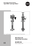
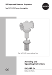
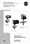
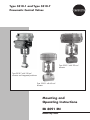
Type 3510-1 and Type 3510-7
Pneumatic Control Valves
Type 3510-1with120 cm²
actuator
Type 3510-7with120 cm²
actuatorandintegratedpositioner
Type 3510-1with60 cm²
actuator
Mounting and
Operating Instructions
EB 8091 EN
Edition July 2002
1
Important safety instructions...........................................................................3
2
Design and principle of operation...................................................................4
3
Assembling and adjusting the valve and actuator............................................6
3.1
Signal pressure connection..............................................................................6
3.2
Assembly and adjustment................................................................................8
4
Installation.....................................................................................................8
4.1
Mounting position...........................................................................................8
5
Operation – Reversing the operating direction.................................................9
6
Troubleshooting.............................................................................................9
6.1
Replacing the packing.....................................................................................9
6.2
Replacing the seat and plug...........................................................................12
7
Customer inquiries.......................................................................................14
Definition of signal words
DANGER!
Hazardous situations which, if not
avoided, will result in death or serious injury
WARNING!
Hazardous situations which, if not
avoided, could result in death or serious injury
2
NOTICE
Property damage message or malfunction
Note:
Additional information
Tip:
Recommended action
EB 8091 EN
Important safety instructions
1 Important safety instructions
−− The valve is to be mounted, started up or operated only by trained and experienced personnel familiar with the product.
According to these mounting and operating instructions, trained personnel refers to individuals who are able to judge the work they are assigned to and recognize possible dangers due to their specialized training, their knowledge and experience as well as their
knowledge of the applicable standards.
−− Any hazards that could be caused in the valve by the process medium, the operating
pressure, the signal pressure or by moving parts are to be prevented by taking appropriate precautions.
To ensure appropriate use, only use the valve in applications where the operating pressure and temperatures do not exceed the specifications used for sizing the valve at the ordering stage.
−− Proper shipping and storage are assumed.
Note:
According to the ignition risk assessment performed in accordance with EN 13463-1,
section 5.2, the non-electrical actuators and valves do not have their own potential
ignition source even in the rare incident of an operating fault. As a result, they do not
fall within the scope of Directive 94/9/EC.
For connection to the equipotential bonding system, observe the requirements specified in section 6.3 of EN 60079-14: 2011 (VDE 0165 Part 1).
EB 8091 EN
3
Design and principle of operation
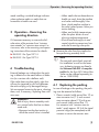
2 Design and principle of operation
The pneumatic control valve consists of a
Type 3510 Micro-flow Valve (with globe or
angle-style body) and a Type 3271-5 Pneumatic Actuator (Type 3510-1 Control Valve)
or a Type 3277-5 Pneumatic Actuator
(Type 3510-7 Control Valve).
The modular design allows the actuators to
be exchanged and an insulating section or
metal bellows to be fitted to the standard
valve version.
The medium flows through the valve in the
direction indicated by the arrow. The posi-
Actuator stem
retracts
tion of the plug (3) determines the flow
through the valve seat (2).
The plug is moved by a change in the signal
pressure acting on the diaphragm of the actuator.
The plug stem (6) is connected to the actuator stem (8.1) by the stem connector (7) and
is sealed by an adjustable PTFE packing.
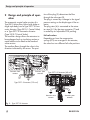
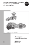
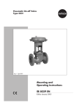
Fail-safe action:
Depending on how the compression
springs (8.3) are arranged in the actuator,
the valve has two different fail-safe positions:
Actuator stem
extends
Type 3271-55 Actuator (60 cm²)
Type 3271-5 Actuator (120 cm²)
Actuator stem
retracts
Actuator stem
extends
Fig. 1: Type 3271-5 Actuator
4
EB 8091 EN
Design and principle of operation
Actuator stem extends:
When the signal pressure is reduced or the
air supply fails, the springs move the actuator stem downwards and close the valve. The
valve opens when the signal pressure is increased enough to overcome the force exerted by the springs.
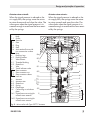
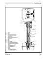
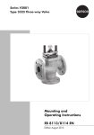
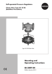
Body
Screw
Seat trim
Seat
Plug
Seal
Anti-rotation fixture with
trim consecutive number
3
Nuts
4
Packing rings
4.1 Packing washer
5
Valve bonnet
5.1 Threaded bushing
5.2 Slotted nut
6
Yoke
6.1 Travel indicator scale
7
Stem connector
7.1 Stem connector nut
7.2 Stem connector sleeve
7.3 Lock nut
8
Actuator
7
8.1 Actuator stem
8.2 Slotted nut
8.3 Spring
8.4 Diaphragm
14
Connecting or switchover
plate
14.1 Signal pressure routing for
actuator stem extends
14.2 Signal pressure routing for
actuator stem retracts
Actuator stem retracts:
When the signal pressure is reduced or the
air supply fails, the springs move the actuator stem upwards and open the valve. The
valve closes when the signal pressure is increased enough to overcome the force exerted by the springs.
1
1.1
2
2.1
2.2
2.3
2.4
8.4
14
14.1
8.3
8
8.1
8.2
7.3
7.1
7.2
5.1
5.2
5
14.2
6
6.1
3
4.1
4
1.1
2.4
2.3
2
2.2
2.1
1
Fig. 2: Micro-valve with Type 3277-7 Actuator
EB 8091 EN
5
Assembling and adjusting the valve and actuator
Mounting accessories
−− Direct attachment: positioners can be
mounted directly to the additional yoke
of the Type 3277 Actuator.
−− Interface according to IEC 60534-6
(NAMUR): a mounting kit (1400-9031)
allows the attachment of positioners, limit
switches, solenoid
valves and other valve
accessories. We recommend using an insulating section or bellows seal for flanged
valves to provide more
space to mount valve
accessories.
3 Assembling and adjusting the
valve and actuator
The different signal pressure connection of
the actuators must be observed on assembly
if the valve and actuator have not been assembled by the manufacturer.
3.1 Signal pressure connection
Type 3510-1 Control Valve
with Type 3271-5 Actuator
ÎÎ Connect the signal pressure line for
valves with actuator with "actuator stem
extends" fail-safe action to the connection on the bottom diaphragm case, and
for valves with actuator with "actuator
stem retracts" fail-safe action to the connection on the top diaphragm case.
6
Type 3510-7 Control Valve
with Type 3277-5 Actuator
If the actuator is operated without a directly
attached positioner, a connecting plate (accessories) is required. In this case, the signal
pressure is routed directly over the signal
pressure connection of the connecting plate
to the actuator diaphragm chamber.
ÎÎ Turn the connecting plate to align the
correct symbol for the fail-safe action
("actuator stem extends" or "actuator
stem retracts") with the marking.
ÎÎ Make absolutely sure that the gasket for
the connecting plate is correctly inserted.
ÎÎ The connecting plate has threaded holes
with NPT and G threads. Seal the connection that is not used with the rubber
seal and square plug.
Actuator with directly attached positioner:
The signal pressure is transmitted to the diaphragm chamber through the holes on the
left or right side of the yoke and over a switchover plate (accessories). The fail-safe action of the actuator ("actuator stem extends"
or "actuator stem retracts") determines how
the switchover plate must be aligned with the
marking.
ÎÎ Turn the switchover plate to align the correct symbol for the fail-safe action with
the marking.
The attachment either on the left or right
side of the actuator is determined by the
required operating direction of the positioner (>>) or (<>).
EB 8091 EN
Assembling and adjusting the valve and actuator
Accessories:
Switchover plates and connecting plates are
listed as accessories.
Actuators with device index .01 (e.g. 3277531xxx20.01) (old = .00) are equipped with
new connecting plates.
Old and new plates are not interchangeable.
Switchover
plate
Switchover
plate
New
Order no. 1400-6822
Old
Order no. 1400-6819
New
Order no. 1400-6823
Old G thread
Order no. 1400-6820
Old NPT thread
Order no. 1400-6821
NOTICE
A supply pressure above the maximum permissible limit will damage
the actuator.
Do not allow the supply pressure to
exceed the maximum permissible limit.
Maximum permissible supply pressure
−− Fail-safe action "actuator stem retracts":
see table below
Signal pressure
range
Adjusted to
Max. perm.
pressure
0.2 to 1
0.4 to 0.8
2.5
0.4 to 2.0
0.8 to 1.6
3.3
1.4 to 2.3
1.7 to 2.1
3.8
2.1 to 3.3
2.4 to 3.0
4.7
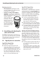
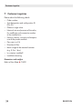
Switchover plate
Connecting plate
Signal pressure
Signal
pressure
Signal pressure
Symbol
Marking
Actuator stem extends
Left
Attach- Right
ment
Actuator stem retracts
Left Attach- Right
ment
Actuator stem
retracts
extends
Fig. 3: Signal pressure connections
EB 8091 EN
7
Installation
−− Fail-safe action "actuator stem extends":
4 bar
3.2 Assembly and adjustment
For actuators with a switchover plate for attachment of a positioner, a suitable adapter
needs to be connected to the hole at the side.
Alternatively, the connecting plate (Fig. 3,
right) can be used.
1. Loosely thread the lock nut (7.3) and
stem connector nut (7.1) upward onto the
plug stem (Fig. 2).
2. Slide slotted nut (8.2) over the stem connector nut and lock nut.
3. Place actuator on valve yoke (7) and fasten tight using slotted nut (8.2).
For actuators with "actuator stem extends", apply approx. 50 % of the signal
pressure range (see nameplate) to the
actuator using a pressure regulator to retract actuator stem far enough to screw
together the stem connector nut (7.1) and
stem connector sleeve (7.2).
4. Screw together stem connector sleeve
(7.2) and stem connector nut (7.1) as
tightly as possible.
5. Apply lower signal pressure range value
to the signal pressure connection.
For a signal pressure range (bench
range) for example, 0.4 to 0.8 bar and
an actuator with fail-safe action "actuator stem extends", the lower signal pressure range value is 0.4 bar; for "actuator
stem retracts" it is 0.8 bar.
6. Turn the stem connector (7) on actuator
stem until the plug stem moves from the
8
closed position at the corresponding lower range value.
To do so, change the signal pressure
each time at the pressure regulator, and
return to the lower range value.
7. Fasten the lock nut (7.3) to secure the
stem connector in this position.
8. Align travel indicator scale (6.1) with the
black ring on the stem connector.
4 Installation
4.1 Mounting position
The valve can be mounted in any desired
position.
The following points must be observed
during installation:
ÎÎ Install the valve free of stress. If necessary, support the pipelines near the connections.
ÎÎ Flush the pipeline thoroughly before installing the valve.
ÎÎ In valve versions with bellows seal or insulating section installed in pipelines that
are to be insulated:
Do not insulate the bellows seal bonnet
or insulating section (9) as well.
Test connection
The version with bellows seal can be fitted
with a test connection (with G 1/8 thread) at
the bellows seal bonnet to allow the tightness
of the bellows to be monitored. We recom-
EB 8091 EN
Operation – Reversing the operating direction
mend installing a suitable leakage indicator
when explosive media or media that are
hazardous to health are used.
−−When media that are hazardous to
health are used, drain the pipeline
and valve and thoroughly rinse
them. Avoid medium residues in
the valve's dead spaces. Wear protective clothing.
−−When used at high temperatures,
allow the plant section to cool
down to ambient temperature.
−−Shut off and lock supply air and
control signals to prevent any hazards due to moving valve parts.
5 Operation – Reversing the
operating direction
If it becomes necessary to reverse the failsafe action of the actuator from "actuator
stem extends" to "actuator stem retracts" or
vice versa, refer to the mounting and operating instructions of the actuator for details.
u EB 8310-1 for Type 3271-5
u EB 8310-1 for Type 3277-5
6 Troubleshooting
External leakage can indicate that the packing is defective or the metal bellows is defective (in a version with a bellows seal).
If the valve does not close tightly, tight shutoff may be impaired by dirt stuck between
the seat and plug or by damaged facings.
We recommend removing the parts, cleaning
them, and, if necessary, replacing them with
new ones.
WARNING!
Risk of injury due to assembly work
on a control valve that has not been
made safe.
−−Depressurize the plant section in
which the control valve is installed.
EB 8091 EN
ÎÎ Remove the valve from the pipeline before performing assembly work.
Note:
The seat and special tools required
for installation as well as the necessary tightening torques are listed in
the document WA 029. A complete
tool kit for the Type 3510 Micro-flow
Valve can be ordered separately (order no. 1280-3050).
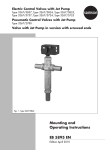
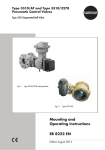
6.1 Replacing the packing
In case of leakage at the packing, the packing must be renewed as follows:
1. Place a wrench (width across flats 17) on
stem connector nut (7.1) and unscrew
stem connector sleeve (7.2) with a second wrench (width across flats 17).
For actuators with "actuator stem extends", apply approx. 50 % of the signal
pressure range (see nameplate) to the
actuator to retract the actuator stem.
9
Troubleshooting
2. Unscrew the bottom slotted nut (5.2). Remove actuator (8) including yoke (6)
from the valve, turning the slotted nut
(5.2) so that a groove points towards the
travel indicator scale (6.1).
3. Remove the nuts (3). Take the stem connector sleeve (7.2) off the plug stem.
4. Remove the screw (1.1), lift off the anti-rotation fixture (2.4) and unscrew the
valve bonnet (5) from the valve body.
5. Unscrew the threaded bushing (5.1). Pull
the plug stem along with the plug (2.2)
out of the valve bonnet (5).
For versions with bellows seal or insulating section: separate the valve bonnet
from the bellows seal bonnet or insulating section (9). The plug stem extension
(10.1, Fig. 5) remains fixed in the intermediate piece.
6. Remove packing washers (4.1) and
packing rings (4) from the packing
chamber using a suitable tool. Make sure
the sealing faces do not get damaged.
Clean the packing chamber thoroughly.
Assembly:
7. Insert new packing rings. Start with a
white ring, followed by two black rings
and another white one. Make sure that
the butt joints of successive rings are not
positioned on top of each other.
8. Insert packing washer(s) (4.1). Tighten
threaded bushing (5.1) manually.
Make sure that a minimum gap of
1.3 mm between valve bonnet and
threaded bushing is observed. If this is
not the case, add the required number of
packing washers (4.1) (min. 1, max. 3
washers).
10.Insert new seal (2.3) into the body.
Screw the valve bonnet into the body.
11.Place the anti-rotation fixture (2.4) on the
valve bonnet, ensuring that the screw
(1.1) is inserted into the long hole. Fasten tight.
12.Slide the stem connector sleeve (7.2) onto the plug stem with the thread facing
upward. Screw on nuts (3). Lock nuts
against each other, so that approx. 1 mm
of the thread is still visible.
13.Place the actuator with yoke onto the
valve bonnet and secure it with the slotted nut (5.2).
For actuators with "actuator stem extends", apply approx. 50 % of the signal
pressure range (see nameplate) to the
actuator using a pressure regulator to retract actuator stem far enough to screw
together the stem connector nut (7.1) and
stem connector sleeve (7.2).
14.Screw together stem connector sleeve
(7.2) and stem connector nut (7.1) as
tightly as possible. Tighten lock nut (7.3).
15.Check adjustment as described in section 3.2, items 5 to 8.
9. Slide plug stem with plug (2.2) into the
valve bonnet as far as it will go. Tighten
threaded bushing (5.1).
10 EB 8091 EN
Troubleshooting
8.1
7.3
7.1
6
6.1
3
7
7.2
5.1
4.1
5.2
5
4
1.1
2.4
1
1.1
2
2.1
2.2
2.3
2.4
3
4
4.1
5
5.1
5.2
6
6.1
7
7.1
7.2
7.3
8.1
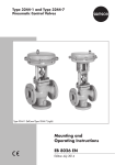
Body
Screw
Seat trim
Seat
Plug
Seal
Anti-rotation fixture
Nuts
Packing rings
Packing washer
Valve bonnet
Threaded bushing
Slotted round nut
Yoke
Travel indicator scale
Stem connector
Stem connector nut
Stem connector sleeve
Lock nut
Actuator stem
2.3
2
2.2
2.1
1
Fig. 4: Replacing the packing
EB 8091 EN
11
Troubleshooting
6.2 Replacing the seat and
plug
Version with insulating section or bellows
seal:
Standard version:
ÎÎ In versions with insulating section, remove the insulating section (9) from the
valve body to allow the plug stem including plug (2.2) to be unscrewed from the
plug stem extension (10.1).
ÎÎ For assembly and disassembly, proceed
as described in section 6.1. Additionally,
unscrew the seat (2.1) using a socket
wrench.
NOTICE
Risk of damage to the seat trim due
to the incorrect exchange of the seat
and plug.
−−On exchanging the seat trim (parts
2.1 to 2.4) with a deviating KVS coefficient, also exchange the anti-rotation fixture. The required anti-rotation fixture is supplied together
with the new seat trim. A consecutive number is written on it (as on
the seat and plug themselves) to indicate which trim parts belong together as well as the material, KVS
coefficient and characteristic.
−−Do not combine seats and plugs
belonging to different trims.
−−Observe the assignment of seat
thread and KVS coefficient (see table below).
After unscrewing the valve bonnet (5)
ÎÎ In versions with bellows seals, unscrew
the bellows seal (10) together with plug
stem extension (10.1) and plug (2.2)
from the bellows seal bonnet (9) using a
bellows wrench.
Unscrew the plug stem along with plug
out of the plug stem extension and separate the bellows seal bonnet from the
valve body.
Before reassembling, renew the seals (9.1
and 9.2). In addition, secure bellows seal
bonnet (9) or insulating section (9) as well as
the valve bonnet using additional anti-rotation fixtures (11 and 12).
The top anti-rotation fixtures (2.4 and 12)
are secured by the washer (15).
Seat thread table
Seat thread
M10 x 1
KVS
coefficient
0.0001 to 0.4
PN max.
400
12 M16 x 1
0.63 to 1.6
100
EB 8091 EN
Troubleshooting
2.4
15
12
9.1
13
16
9.2
10
1.1
2.2
2.4
Screw
Plug
Anti-rotation fixture with
trim consecutive number
5
Valve bonnet
9
Bellows seal bonnet/insulating section
9.1 Seal
9.2 Seal
10
Bellows seal
10.1 Plug stem extension (version
with bellows seal or insulating
section)
11
Anti-rotation fixture
12
Anti-rotation fixture
13
Screw
15
Washer
16
Test connection (option)
10.1
9
11
1.1
2.2
Fig. 5: Version with bellows seal
EB 8091 EN
13
Customer inquiries
7 Customer inquiries
Please submit the following details:
−− Order number
−− Type designation and configuration ID
(Var.-ID)
−− Globe or angle valve
−− Nominal size and pressure of the valve,
KVS coefficient and consecutive number
of the installed trim
−− Pressure, density, viscosity and temperature of the process medium
−− Flow rate in m³/h
−− Direction of flow
−− Bench range of the mounted actuator
(e.g. 0.2 to 1 bar)
−− Is a strainer installed?
−− Installation drawing
Dimensions and weights
Refer to Data Sheet u T 8091
14 EB 8091 EN
Weismüllerstraße 3 · 60314 Frankfurt am Main, Germany
Phone: +49 69 4009-0 · Fax: +49 69 4009-1507
[email protected] · www.samson.de
EB 8091 EN
2015-04-13 · English
SAMSON AG · MESS- UND REGELTECHNIK