1
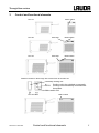
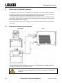
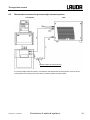
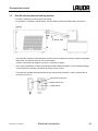
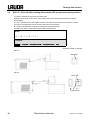
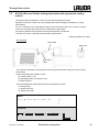
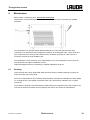
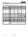
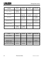
Operating instructions Through-flow coolers DLK 10, DLK 25, DLK 45, DLK 45-LiBus Read the operating instructions before starting all work. Valid from series : 04-0001 (see item 9.3) release english e1 replaces release 06/04 YAFE0004 LAUDA DR. R. WOBSER GMBH & CO. KG P.O. Box 1251 97912 Lauda-Königshofen Germany Phone : +49 (0)9343 503-0 Fax : +49 (0)9343 503-222 E-mail [email protected] Internet http://www.lauda.de Through flow coolers Safety notes Before you operate the unit please read carefully all the instructions and safety notes. If you have any questions please phone us! Follow the instructions on setting up, operation etc. This is the only way to avoid incorrect operation of unit and to ensure full warranty protection. • Transport the unit with care! The unit may NEVER be overturned nor put upside down! • Unit and its internal parts can be damaged : − by dropping − by shock. • Unit must only be operated by technically qualified personnel! • Never operate the equipment without the heat transfer liquid! • Do not start up the unit if − it is damaged − the supply cable is damaged. • Switch off the unit and pull out the mains plug for : − servicing or repair − before moving the unit. • Have the unit serviced or repaired only by properly qualified personnel! The Operating Instructions include additional safety notes which are identified by a triangle with an exclamation mark. Carefully read the instructions and follow them accurately! Disregarding the instructions may have serious consequences, such as damage to the unit, damage to property or injury to personnel! We reserve the right to make technical alterations! 29/07/2015 / YAFE0004 Safety notes 3 Through flow coolers Contents SAFETY NOTES .................................................................................................................................................... 3 CONTENTS .......................................................................................................................................................... 4 1 SAFETY INFORMATION .............................................................................................................................. 5 1.1 GENERAL SAFETY NOTES .......................................................................................................................... 5 1.2 OTHER SAFETY NOTES .............................................................................................................................. 5 2 BRIEF OPERATING INSTRUCTIONS ......................................................................................................... 6 3 CONTROL AND FUNCTIONAL ELEMENTS ............................................................................................... 7 4 GENERAL CONSTRUCTION AND TECHNICAL DESCRIPTION ............................................................... 8 5 UNPACKING AND SETTING UP .................................................................................................................. 9 6 7 5.1 UNPACKING .............................................................................................................................................. 9 Standard accessories ................................................................................................................................................. 9 5.2 SETTING UP.............................................................................................................................................. 9 CONNECTION OF EXTERNAL SYSTEMS ................................................................................................ 10 6.1 THERMOSTATS WITHOUT EXTERNAL SYSTEMS .......................................................................................... 10 6.2 THERMOSTATS CONNECTED TO PRESSURE-TIGHT EXTERNAL SYSTEMS ..................................................... 11 6.3 THERMOSTATS WITH DUPLEX PUMP OR PRESSURE/SUCTION PUMP CONNECTED TO OPEN BATH .............. 12 ELECTRICAL CONNECTION ..................................................................................................................... 13 7.1 DLK 10 / 25 / 45 AND THERMOSTAT WITHOUT MAINS SUPPLY OUTPUT 34H ............................................... 13 7.2 DLK 10 / 25 / 45 AND THERMOSTAT WITH MAINS SUPPLY OUTPUT 34 H .................................................... 14 7.3 DLK 45 WITH PROPORTIONAL COOLING METHOD ...................................................................................... 15 7.4 DLK 10 / 25 AND PROLINE HEATING THERMOSTATS WITH PROPORTIONAL COOLING METHOD...................... 16 7.5 DLK 45-LIBUS AND PROLINE HEATING THERMOSTATS WITH PROPORTIONAL COOLING METHOD .................. 17 8 STARTING UP ............................................................................................................................................ 18 9 MAINTENANCE .......................................................................................................................................... 19 9.1 CLEANING .............................................................................................................................................. 19 9.2 REPAIR AND DISPOSAL NOTE ................................................................................................................... 20 9.3 HELP DESK AND ORDERING REPLACEMENT PARTS .................................................................................... 20 10 TECHNICAL DATA ..................................................................................................................................... 21 Special Symbols: 4 Danger: This symbol is used where there may be injury to personnel through incorrect handling. Note: Here special attention is drawn to some aspect. May include reference to danger. Reference Refers to additional information in other sections. Contents 29/07/2015 / YAFE0004 Through flow coolers 1 Safety information 1.1 General safety notes A through flow cooler serves for due cooling of heat transfer liquids which are tempered by means of a bath thermostat and transferred by pumping. This leads to hazards through high temperatures, fire, and the general hazards through the use of electrical energy. The user is largely protected through the application of the appropriate standard specifications. Additional hazards may arise from the type of material being thermostated, e.g. when going above or below certain temperature levels or through breaking of the container and reaction with the heat transfer liquid. It is not possible to cover all possibilities; they remain largely within the responsibility and the judgement of the user. The equipment must only be used as intended and as described in these Operating Instructions. This includes operation by suitably instructed qualified personnel. The units are not designed for use under medical conditions according to EN 60601-1 or IEC 601-1! 1.2 Other safety notes • Connect the equipment only to an earthed supply socket. • Use suitable hoses. • Protect tubing with hose clips against slipping off. Prevent kinking of tubing! • Check tubing from time to time for possible material fatigue! • Heat transfer tubing and other hot parts must not come into contact with the supply cable!! • During operation of the through flow cooler, hot tempering liquid may penetrate through the hose in case of hose rupture, thus constituting a danger to persons and material goods. • Depending on the heat transfer liquid used and the method of operation it is possible for toxic vapours to be produced. Ensure appropriate ventilation!! • When changing the heat transfer liquid from water to liquids for temperatures above 100 °C carefully remove all traces of water, also from tubing and from the external circuit, otherwise danger of burns through delayed boiling! • Always pull out the mains plug before cleaning, maintenance or moving the through-flow cooler! • Repairs must only be carried out by properly qualified personnel! • Values for temperature control and indicating accuracy apply under normal conditions according to DIN 12876. High-frequency electromagnetic fields may under special conditions lead to unfavourable values. This does not affect safety! 29/07/2015/ YAFE0004 Safety information 5 Through flow coolers 2 Brief operating instructions Check through-flow cooler during unpacking for any transport damage, and if necessary, inform the carrier or the post office. The unit may NEVER be overturned nor put upside down! - Set up unit according to chapter 5. - Connect tubing according to chapter 6. • Thermostats without external systems ( Chapter 6.1). • Thermostats connected to pressure-tight external systems ( Chapter 6.2). • Thermostats with DUPLEX pump or pressure/suction pump connected to open bath ( Chapter 6.3). - Secure tubing with clips to prevent slipping-off. - Check the supply voltage against the data on the rating label. Insert the mains plug. Switching on: First switch on thermostat, and then switch on through-flow cooler at main power switch (green signal lamp lights up). Switching off: First switch off through-flow cooler, and then switch off thermostat. Never allow the through-flow cooler to run without liquid flowing through. 6 Brief operating instructions 29/07/2015/ YAFE0004 Through flow coolers 3 Control and functional elements DLK 10 Mains switch DLK 25 Pilot lamp Mains switch DLK 45 Pilot lamp Mains switch Switches located on the through flow coolers DLK 25 and DLK 45 Pilot lamp cooling unit AUTO Cooling unit to be switched on manually. Cooling unit automatically controlled with thermostat. Mains switch ON DLK 45-LiBus 29/07/2015/ YAFE0004 Mains switch Control and functional elements 7 Through flow coolers 4 General construction and technical description These operating instructions apply to four through-flow coolers of various cooling capacities. Common feature of all four units are the air-cooled, fully hermetically sealed and thus maintenancefree refrigeration units, the heat carrier circuit in stainless steel and the possibility of electrical connection to LAUDA thermostats. The refrigeration unit consists essentially of a hermetically sealed compressor. Heat of condensation and motor heat are dissipated through a fan-cooled finned tube condenser. The fresh air is drawn in at the front of the unit; the heated is discharged to the back and to the side. In order to ensure problemfree air circulation the ventilation openings must not be obstructed. The compressors have an over-temperature cut-out which acts on the compressor temperature and current consumption of compressor. Furthermore the cooling system is protected by an overpressure cut-out against excessive pressure. The built-in refrigeration unit continuously cools down a heat exchanger (evaporator) insulated with polyurethane foam. The connections of the heat exchanger are mounted at the back and are provided with tube fittings M16 x 1 to connect olives with a diameter of 13 mm / 11 mm or metal hoses. The pump of the connected thermostat pumps the heat transfer liquid through the heat exchanger of the through-flow cooler. The through-flow cooler continuously cools down and the thermostat maintains the required temperature by means of controlled counter-heating. The through flow cooler DLK 45 equipped with LAUDA heating thermostats of the Ecoline E 3XX series and older thermostats with incorporated P electronics allow a method of operation corresponding to the proportional cooling. The cooler DLK 45-LiBus with LAUDA heating thermostats with LiBus (at present Proline) also allows a method of operation which is equivalent to the proportional cooling. The cooling capacities indicated in the technical data sheet are gross values. To get the true effective cooling capacities in case of operation, the heat emission of the pump as well as the insulation losses have to be taken into consideration and deducted. This is decisive for the lowest temperature which can be reached if a thermostat is connected. The indicated operating temperature range refers to the combination with a small or medium-sized bath/circulation thermostat. (i. e. DLK 10 – E 103; DLK 25 – P 8 C; DLK 45 – PVL 24.) 8 General construction and technical description 29/07/2015/ YAFE0004 Through flow coolers 5 Unpacking and setting up The unit may NEVER be overturned nor put upside down! 5.1 Unpacking Carefully packing should prevent transport damage. If, however, the units should arrive damaged, the carrier or the post office has to be informed so that it can be inspected. Standard accessories Cat. No. 2 Screw caps HKM 032 2 Olives Ø13 mm HKO 026 1 DLK Mains cable DLK 10, DLK 25 UK 226 1 valve control line DLK 45 for Ecoline E 3XX and P control unit thermostat UK 251 1 power control line DLK 45 for Ecoline E 3XX and P control unit thermostat UK 227 1 Operating Instructions for all DLK YAFE0004 Optional accessories 5.2 Cat. No. 1 power control line DLK 10, 25 for Ecoline E 3XX and P control unit thermostat UK 227 1 Proline control line DLK 10, 25 UK 263 1 LiBus extension, 5 m DLK 45-LiBus EKS 068 1 LiBus T-distributor DLK 45-LiBus EKS 073 Setting up air outlet air inlet The condenser of the refrigeration unit is air-cooled. Fresh air is drawn in at the front of the unit and blown out at the back. Thus the unit must be set up so that the free air flow is not obstructed. Recommended distance: 50 centimetre at least. It is particularly important that the air drawn in is not excessively warm. The unit must not be placed near a radiator or any other source of heat. Higher ambient temperatures result in a reduced performance. When the compressor is overloaded because of high refrigerant pressure or high ambient temperature, the power supply is automatically interrupted via a temperature switch. The compressor switches on automatically as soon as it has cooled down. 29/07/2015/ YAFE0004 Unpacking and setting up 9 Through flow coolers 6 Connection of external systems A through-flow cooler can be only connected to thermostats which are equipped with a circulating pump and connectors for the connection of external circulating systems. For connection the use of insulated tubing with a maximum possible inside diameter is recommended. To guarantee good circulation of the pump the tubing should not be too long. If possible, place the through-flow cooler directly near the thermostat, especially when operating with the DLK 45 and the DLK45-LiBus with proportional cooling. Secure tubing with clips to prevent its slipping off or use stainless steel metal hoses with screwed connections! 6.1 Thermostats without external systems Thermostat DLK The figure shows the easiest possibility of connection. The connectors of the circulating pump are connected to the fittings of the through-flow cooler. − 10 Pay attention to the through-flow direction! If the connections are interchanged, the cooling capacity will be reduced as an air cushion may develop in the plate-heat exchanger. Connection of external systems 29/07/2015 / YAFE0004 Through flow coolers 6.2 Thermostats connected to pressure-tight external systems Thermostat DLK pressure-tight consuming device If a pressure-tight external system is connected to the thermostat, the through-flow cooler must be incorporated in the return line (suction line) of external system and thermostat. 29/07/2015 / YAFE0004 Connection of external systems 11 Through flow coolers 6.3 Thermostats with DUPLEX pump or pressure/suction pump connected to open bath Thermostat DLK constant level device open bath If the thermostat is equipped with a DUPLEX pump or a pressure/suction pump and an open bath is thermostated, it is also possible to connect the through-flow cooler. The through-flow cooler must be incorporated in the return line (suction line). 12 - Only possible with devices provided with suction press pump. - Use constant level device on the open bath. - Not possible with LAUDA Ecoline. Connection of external systems 29/07/2015 / YAFE0004 Through flow coolers 7 Electrical connection 7.1 DLK 10 / 25 / 45 and Thermostat without mains supply output 34H First switch on thermostat, then switch on through-flow cooler by means of the mains switch (green signal lamp lights up). Switches located on the DLK DLK 10 Mains ON 37 H DLK- Mains cable UK 226 Only switch on the mains switch if thermostat is in operation. DLK 25 38 H (not used) Adjust (manual). 37 H DLK- Mains cable UK 226 Only switch on the mains switch if thermostat is in operation. Unit cools if the mains switch is switched ON. DLK 45 39 H (not used) Adjust (manual). 38 H (not used) DLK- Mains cable Only switch on the mains switch if thermostat is in operation. Unit cools if the mains switch is switched ON. 29/07/2015/ YAFE0004 Electrical connection 13 Through flow coolers 7.2 DLK 10 / 25 / 45 and Thermostat with mains supply output 34 H The DLK is switched on and off by the thermostat. This output is provided on Ecoline E 3XX and older LAUDA thermostats with P electronics! The system operates with continuous cooling and controlled heating. The DLK only cools in case that the thermostat is switched ON. Switches located on the DLK DLK 10 Mains ON DLK 25 Mains cable Mains ON Adjust AUTO DLK 45 not used Mains cable Mains ON Adjust AUTO When using thermostats with P electronics select “DLK standard” in the menue “Parameters”! 14 Electrical connection 29/07/2015 / YAFE0004 Through flow coolers 7.3 DLK 45 with proportional cooling method The DLK is switched on and off by the thermostat. It is possible in combination with Ecoline E 3XX and older LAUDA thermostats with P electronics! DLK 45 Mains cable This method of operation offers the same functions as the proportional cooling at LAUDA refrigerated thermostat. This method does not use counterheating. Caution: Thermostat with software version 2.14 minimum or higher. In the menu “parameters” of the thermostat either DLK standard operation (= with controlled heating) or DLK automatic operation (=proportional cooling) can be chosen. For automatic operation with proportional cooling choose „DLK automatic“. Put the yellow switch at the DLK 45 to AUTO. Pilot lamp Cooling unit Mains switch ON Adjust AUTO 29/07/2015 / YAFE0004 Electrical connection 15 Through flow coolers 7.4 DLK 10 / 25 and Proline heating thermostats with proportional cooling method The DLK is switched on and off by the thermostat. Operation of the DLK control unit is only possible with Proline heating thermostats (no cooling thermostats!). The "No." specified on the rating plate located on the back of the master unit, must be ≥ 04-0001. The use of a through flow cooler has to be defined in the thermostat. The system operates with continuous cooling and controlled heating. The DLK only cools in case that the thermostat is switched ON. Master: MNEnu PArA tFC = 1 Command: Menu Settings Basic Settings DLK connected = Yes Switches located on the DLK DLK 10 Mains ON DLK 25 Mains ON Adjust AUTO 16 Electrical connection 29/07/2015 / YAFE0004 Through flow coolers 7.5 DLK 45-LiBus and Proline heating thermostats with proportional cooling method The DLK 45-LiBus is switched on and off by the Proline heating thermostat. Operation of the DLK control unit is only possible with Proline heating thermostats (no cooling thermostats!). The “No.” specified on the rating plate located on the back of the master unit, must be ≥ 04-0001. The use of a through flow cooler has to be defined in the thermostat. The system operates with proportional cooling and automatic compressor. The DLK only cools in case that the thermostat is switched ON. Switches located on the DLK DLK 45-LiBus LiBus-cable Mains ON DLK mains cable This method of operation has the same functions as the proportional cooling of LAUDA cooling thermostats. Proline thermostat with software version: for control system V1.33 for operating system (command) V1.36 or higher required. The thermostat allows switching between the following DLK modes: "0" (always OFF), "1" (always ON) and "A" (automatic mode). Master: MNEnu MNodu Cool Co 0 1 A Command: Menu Interfaces SmartCool Cooling mode 29/07/2015 / YAFE0004 Electrical connection off on automatic 17 Through flow coolers 8 Starting up • Always connect the unit to a grounded socket only. Check details on the type label against the supply voltage. • Secure hoses against slippage with the aid of hose clips. • When the DLK is connected to a thermostat, switch the thermostat on. The DLK control unit must be activated in the thermostat in any case if it’s an Ecoline E 3XX, Proline or P control unit thermostat. • Switch on the mains switch (green) on the DLK. • If the DLK 25 or the DLK 45 has to be controlled by a thermostat, the cooling switch (yellow) must be switched to the AUTO position. ( Chapter 7.2, 7.3 and 7.4) The through-flow cooler automatically starts running together with the thermostat. The yellow signal lamp indicates that the refrigeration unit is switched on. The DLK is protected against freezing because there is no through-flow when pump is not running. • For manual operation, position the cooling switch (yellow) on neutralized. ( Chapter 7.1) . The AUTO function is then NOTE: Switching on: First switch on thermostat, then switch on through-flow cooler by means of the mains switch (green signal lamp lights up). Switching off: First switch off through-flow cooler, then thermostat. Never allow the through-flow cooler to run without liquid as in this case the remaining liquid in the exchanger will excessively be cooled down to lowest temperature. It will freeze resulting in damaging the exchanger. 18 Starting up 29/07/2015/ YAFE0004 Through flow coolers 9 Maintenance Before repair or cleaning is done, pull out the mains plug! Repair at the control panel and the lower part of the unit should only be executed by a qualified electrician. The refrigeration unit operates largely without maintenance. If the units operate under dusty conditions we recommend that the refrigerator condenser is cleaned quite often. This is done best with compressed air or nitrogen that is blown into the ventilation openings for a few minutes. If necessary unscrew the front ventilation grill. The refrigeration circuit of the DLK 10 is charged with R 134 a, the refrigeration circuit of DLK 25, DLK 45 and DLK 45-LiBus is filled with R 404 A. Repair and disposal must be executed by a qualified refrigeration engineer. 9.1 Cleaning Clean the units with a cloth, wetted with water and some drops of tensids (washing-up liquid). No water must enter the control panel. The user is responsible for any necessary decontamination if dangerous materials have been spilled on or inside the unit. This applies in particular if the unit is removed for a different use, for repair, storage etc. The method of cleaning or decontamination is determined by the expertise of the user himself. If the user has any doubts on whether this may damage the unit he can contact the manufacturer. 29/07/2015 / YAFE0004 Maintenance 19 Through flow coolers 9.2 Repair and disposal note The cooling circuit is filled with CFC-free refrigerant. Type and quantity are marked on the unit. Repair and disposal only by a qualified refrigeration engineer! Before you return the equipment for servicing it is advisable to contact our Technical Service department. 9.3 − If the equipment has to be returned to the factory, please ensure that it is carefully and properly packed. LAUDA accepts no responsibility for damage due to unsatisfactory packing. Help desk and ordering replacement parts When ordering replacement parts, please state the device type and number as given on the name plate. This avoids queries and incorrect supply. The serial number is combined like following, for example, LFD010-15-0001 LFD010 = 15 = 0001 = article order number manufacturing 2015 continuous numbering Your contact for service and support LAUDA Service Constant Temperature Equipment Telephone: +49 9343 503-372 (English and German) E-Mail [email protected] We shall always be happy to deal with queries and to receive suggestions and criticism! LAUDA DR. R. WOBSER GMBH & CO. KG P.O. Box 1251 97912 Lauda-Königshofen Germany Telephone : +49 9343 503-0 Fax : +49 9343 503-222 E-mail [email protected] Internet: http://www.lauda.de/ 20 Maintenance 29/07/2015 / YAFE0004 Through flow coolers 10 Technical data The figures have been determined according to DIN 12876 Operating temperature range °C Ambient temperature range °C DLK 10 DLK 25 DLK 45 DLK 45-LiBus -15...150 -30...150 -40...150 -40...150 5...40 Gross cooling capacity (to DIN 12876 T2) 20 °C 0 °C -10 °C -20 °C -30 °C -40 °C kW kW kW kW kW kW 0.25 0.20 0.10 ---------------- Heat exchanger connections for heat carrier 0.33 0.28 0.25 0.22 0.20 ------ 1.10 0.95 0.85 0.75 0.55 0.30 1.10 0.95 0.85 0.75 0.55 0.30 M16 x 1, olives diameter 13 mm control connection for mains supply Special features Heat exchanger coaxial Proportional- Proportional-cooling cooling with with Proline heating thermostat C/K-P or E 300 plate-heat exchanger Overall dimensions WxDxH mm 200 x 400 x 320 290 x 540 x 330 470 x 560 x 430 470 x 560 x 430 Weight kg 17 33 63 63 Protection class Power consumption EU Directives 29/07/2015/ YAFE0004 Protection class 1 according to DIN EN 61140 VDE 0140-1 kW 0.2 0.5 0.9 0.9 The units are conformable to directives of the European Parliament and of the Council: 2004/108/EC electromagnetic compatibility and 2006/95/EC electrical equipment designed for use within certain voltage limits. Technical data 21 Through flow coolers two fuses per device F1 and F2 DLK 10 DLK 25 DLK 45 DLK 45-LiBus T 6,3 A 5 x 20 mm (EEF 006) ----- ----- ----- 230 V; 50/60 Hz ----- T8A 5 x 20 mm (EEF 028) T 16 A 6.3 x 32 mm (EES 013) T 16 A 6.3 x 32 mm (EES 013) ----- T8A 5 x 20 mm (EEF 028) ----- T 16 A 6.3 x 32 mm (EES 013) ----- ----- ----- T 16 A 6.3 x 32 mm (EES 013) ----- ----- T 16 A 6.3 x 32 mm (EES 013) ----- T 10 A 5 x 20 mm (EEF 026) T 16 A 5 x 20 mm (EEF 024) ----- ----- 100 V; 50 Hz / 115 V; 60 Hz Cat. No. DLK 10 DLK 25 DLK 45 DLK 45-LiBus 230 V; 50/60 Hz LFD 010 ----- ----- ----- 230 V; 50 Hz ----- LFD 108 LFD 109 LFD 111 230 V; 60 Hz ----- LFD 208 ----- LFD 211 208-220 V; 60 Hz ----- ----- ----- LFD 811 208-230 V; 60 Hz ----- ----- LFD 809 ----- 100 V; 50 Hz / 115 V; 60 Hz LFD 710 LFD 708 ----- ----- 230 V; 50 Hz 230 V; 60 Hz 208-220 V; 60 Hz 208-230 V; 60 Hz We reserve the right to make technical alterations! 22 Technical data 29/07/2015/ YAFE0004 BESTÄTIGUNG / CONFIRMATION / CONFIRMATION An / To / A: LAUDA Dr. R. Wobser • LAUDA Service Center • Fax: +49 (0) 9343 - 503-222 Von / From / De : Firma / Company / Entreprise: Straße / Street / Rue: Ort / City / Ville: Tel.: Fax: Betreiber / Responsible person / Personne responsable: Hiermit bestätigen wir, daß nachfolgend aufgeführtes LAUDA-Gerät (Daten vom Typenschild): We herewith confirm that the following LAUDA-equipment (see label): Par la présente nous confirmons que l’appareil LAUDA (voir plaque signalétique): Typ / Type / Type : Serien-Nr. / Serial no. / No. de série: mit folgendem Medium betrieben wurde was used with the below mentioned media a été utilisé avec le liquide suivant Darüber hinaus bestätigen wir, daß das oben aufgeführte Gerät sorgfältig gereinigt wurde, die Anschlüsse verschlossen sind, und sich weder giftige, aggressive, radioaktive noch andere gefährliche Medien in dem Gerät befinden. Additionally we confirm that the above mentioned equipment has been cleaned, that all connectors are closed and that there are no poisonous, aggressive, radioactive or other dangerous media inside the equipment. D’autre part, nous confirmons que l’appareil mentionné ci-dessus a été nettoyé correctement, que les tubulures sont fermées et qu’il n’y a aucun produit toxique, agressif, radioactif ou autre produit nocif ou dangeureux dans la cuve. Stempel Datum Betreiber Seal / Cachet. Date / Date Responsible person / Personne responsable Formblatt / Form / Formulaire: Erstellt / published / établi: Änd.-Stand / config-level / Version: Datum / date: UNBEDENK.DOC Unbedenk.doc LSC 0.1 30.10.1998 LAUDA DR. R. WOBSER GmbH & Co. KG Pfarrstraße 41/43 Tel: D - 97922 Lauda-Königshofen Fax: Internet: http://www.lauda.de E-mail: +49 (0)9343 / 503-0 +49 (0)9343 / 503-222 [email protected]