1
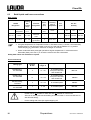
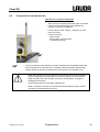
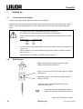
Operating Instructions
Class RA
Cooling thermostats
RA 104, RA 106 and RA 120
Valid from series 05-0001 (see item 8.3)
10/05
YAEE0018
LAUDA DR. R. WOBSER
GMBH & CO. KG
Post office box 1251
97912 Lauda-Koenigshofen
Germany
Phone: 0049 (0)9343/ 503-0
Fax: 0049 (0)9343/ 503-222
E-mail: [email protected]
Internet http://www.lauda.de
Class RA
Safety notes
Before operating the equipment please read carefully all the instructions and safety
notes. If you have any questions please phone us!
Follow the instructions on setting up, operation etc. This is the only way to avoid
incorrect operation of the equipment and to ensure full warranty protection.
•
Transport the equipment with care!
The unit may NEVER be overturned nor put upside down!
•
Equipment and its internal parts can be damaged:
− by dropping
− by shock.
•
Equipment must only be operated by technically qualified personnel!
•
Never operate the equipment without the bath liquid!
•
Do not start up the equipment, if
− it is damaged or leaking,
− the supply cable is damaged.
•
Switch off the equipment and pull out the mains plug:
− for servicing or repair
− before moving the equipment!
•
Drain the bath before moving the equipment!
•
Do not carry out any technical changes on the device!
•
Have the equipment serviced or repaired by properly qualified personnel only!
The Operating Instructions include additional safety notes which are identified by a triangle with
an exclamation mark. Carefully read the instructions and follow them accurately! Disregarding the
instructions may have serious consequences, such as damage to the equipment, damage to
property or injury to personnel!
We reserve the right to make technical alterations!
YAEE0018 / 07.03.2006
Safety notes
3
Class RA
TABLE OF CONTENTS
Safety notes ....................................................................................................................................3
1
SAFETY NOTES...........................................................................................................................6
1.1
General safety notes ............................................................................................................6
1.2
Other safety notes ................................................................................................................6
2
BRIEF OPERATING INSTRUCTIONS .........................................................................................8
3
CONTROL AND FUNCTIONAL ELEMENTS ...............................................................................9
4
UNIT DESCRIPTION ..................................................................................................................10
4.1
Environmental conditions..................................................................................................10
4.2
Unit types ............................................................................................................................10
4.3
Baths....................................................................................................................................10
4.4
Pump....................................................................................................................................10
4.5
Materials ..............................................................................................................................11
4.6
Temperature indication, control and safety circuit .........................................................11
4.7
Refrigeration system ..........................................................................................................11
5
UNPACKING...............................................................................................................................12
6
PREPARATIONS........................................................................................................................13
7
8
6.1
Assembly and setting up ...................................................................................................13
6.2
Filling and emptying...........................................................................................................14
6.3
Bath liquids and hose connections ..................................................................................16
6.4
Connection of external circuits .........................................................................................17
STARTING UP ............................................................................................................................18
7.1
Connection to the supply...................................................................................................18
7.2
Switching on .......................................................................................................................18
7.3
Set point selection..............................................................................................................19
7.4
Warning and safety functions ...........................................................................................19
7.4.1
Overtemperature protection and testing ..................................................................................19
7.4.2
Low-level protection ...................................................................................................................20
7.4.3
Pump motor monitoring .............................................................................................................21
MAINTENANCE..........................................................................................................................22
8.1
4
Cleaning...............................................................................................................................22
Table of contents
07.03.2006 / YAEE0018
Class RA
8.2
Maintenance and repair..................................................................................................... 22
8.2.1
Maintenance of the refrigeration unit .......................................................................................23
8.2.2
Note on repair and disposal ......................................................................................................23
Repair and disposal by a qualified refrigeration engineer only! ..............................................................23
8.3
9
10
Ordering spares ................................................................................................................. 24
TECHNICAL DATA (ACCORDING TO DIN 12876) ...................................................................... 25
ACCESSORIES ...................................................................................................................... 27
YAEE0018 / 07.03.2006
Table of contents
5
Class RA
1
Safety notes
1.1
General safety notes
A laboratory thermostat is intended for heating and pumping liquids according to the needs of the user.
This leads to hazards by high temperatures, fire, and the general hazards by the use of electrical
energy.
The user is largely protected through the application of the appropriate standard specifications.
Additional hazards may arise from the type of material being thermostated, e.g. when going above or
below certain temperature levels or through breaking of the container and reaction with the
thermostating liquid.
It is not possible to cover all possibilities; they remain largely within the responsibility and the judgement
of the user.
The unit must only be used as intended and as described in these Operating Instructions. This includes
operation by suitably instructed qualified personnel.
The units are not designed for use under medical conditions according to EN 60601-1 or IEC 601-1 !
1.2
Other safety notes
•
Connect the unit only to grounded mains power (PE).
•
Parts of the bath cover may reach surface temperatures above 70 °C when operating at higher
temperatures. Take care when touching it!
•
Use suitable hoses
•
Protect tubing with hose clips against slipping off. Prevent kinking of tubing!
•
Check tubing from time to time for possible material defects!
•
Heat transfer tubing and other hot parts must not come into contact with the supply cable!
•
When using the thermostat as circulation thermostat, failure of tubing may lead to leaking of hot
liquid and become a danger to personnel and objects.
•
When no external consumer is connected to the thermostat the pump outflow must be linked to the
return!
Section 6.3.
• The units are designed for operation with non-flammable liquids to EN 61010-2-010 only.
6
•
Depending on the bath liquid used and the mode of operation it is possible for toxic vapours to be
produced. Ensure appropriate ventilation!
•
Always pull out the mains plug before cleaning, maintenance or moving the thermostat!
•
Repairs on the control unit and the refrigeration system must be carried out by properly qualified
personnel only.
•
Values for temperature control and indicating accuracy apply under normal conditions according to
DIN 12876. High-frequency electromagnetic fields may under special conditions lead to
unfavourable values. This does not affect the safety!
Safety notes
07.03.2006 / YAEE0018
Class RA
Explanation of signs:
YAEE0018 / 07.03.2006
Danger:
This sign is used where there may be injury to
personnel if a recommendation is not followed
accurately or is disregarded.
Note
Here special attention is drawn to some aspect. May
include reference to danger.
Reference:
Refers to other information in different sections.
Explanation of signs
7
Class RA
2
Brief operating instructions
This brief instruction shall give you the possibility to operate the unit quickly. For safe
operation of the unit it is absolutely necessary to read carefully all the instructions and safety
notes!
1. Assemble unit and add items as appropriate ( Section 6.)
The unit may NEVER be overturned nor put upside down!
Take care of the hose connections ( Section 6.3 and 6.4)
2. Fill the unit with corresponding liquid ( Section 6.3) The units are designed for operation with nonflammable liquids to EN 61010-2-010. Æ Take care of the level of the bath liquid! ( Section 6.2)
3. Connect the equipment only to a socket with a protective earth (PE) connection. Compare the
information on the rating label with the supply details.
4.
Set the overtemperature cut-out point to a value clearly above ambient
temperature ( Section 7.4.1)
5.
Switch on at the mains switch (green).
6. The refrigeration unit is to be switched on manually (yellow switch), if cooling is needed.
8
Brief operating instructions
07.03.2006 / YAEE0018
Class RA
3
Control and functional elements
Reference thermometer
Pilot lamp „Heater“
Pilot lamp „Fault“
Temperature adjustment
Overtemperature adjustment and push
button ”Reset”
Mains switch and switch for the cooling
unit
Heater
Jet nozzle
Pump connections:
– Return to the bath
– Pump outflow, Pressure output
( labelling housing)
RA 104
YAEE0018 / 07.03.2006
RA 106
Control and functional elements
RA 120
9
Class RA
4
Unit description
4.1
Environmental conditions
The operation of the thermostats is only allowed under the following conditions as specified in
EN 61010-2-010:2003 and EN 61010-1:2001:
4.2
−
Indoor use.
−
Altitude up to 2000 m above sea level.
−
Foundation must be dense, even, non-slippery and non-flammable.
−
Keep clear distance (
−
Ambient temperature range ( Section 9).
Use only within this range for an undisturbed operation.
−
Mains supply voltage fluctuations ( Section 9).
−
Maximum relative humidity 80 % for temperatures up to 31 °C, decreasing linearly to 50 % relative
humidity at 40 °C.
−
Transient over voltage according to Installation Categories (Over voltage Categories) II.
−
Pollution degree: 2.
Section 6.1).
Unit types
The type designation of the Class RA low-temperature thermostats consists of the letter R (identification
as low-temperature unit), the control unit A 100 and the type of bath and refrigeration system.
Example:
Refrigeration unit R, control unit A 100 and bath and refrigeration system 004 produces
thermostat type RA 104.
Type RA 120 is supplied without bath cover. A bath cover is available as accessory.
( Section 10 Accessories).
4.3
Baths
All units provide a stainless steel bath. The last two digits of the model no. correspond to the
approximate total volume in Litre (e.g. bath RA 106 = approx. 6 Litre).
Part of this volume may be used to insert objects.
4.4
Pump
All units are equipped with a pressure pump. The pumps are driven by a shaded pole motor.
The pump outflow connection can be closed without causing any damage to the pump.
Pump characteristics (
10
section 9 Technical data).
Unit description
07.03.2006 / YAEE0018
Class RA
4.5
Materials
All parts which come into contact with the bath liquid are made from high-grade materials appropriate to
the operating temperature. Rust-free stainless steel is being used.
4.6
Temperature indication, control and safety circuit
The units are provided with a potentiometer for analogue temperature setting (resolution approx. 0,3 °C).
The actual bath temperature is indicated on a reference thermometer (glass) with a resolution of 0,5 °C.
The thermostats are provided with an adjustable overtemperature cut out switch avoiding the operation
of the heater in case of an insufficient bath level.
The pump motor is provided with a temperature protector which avoids an overtemperature of the
motor. Both functions will switch off heater and pump.
With a P-controller the heating capacity is electronically controlled by a zero voltage packed switching
triac.
4.7
Refrigeration system
The refrigeration system consists essentially of a hermetically sealed compressor. Heat of condensation
and motor heat are dissipated by a fan-cooled finned condenser. Fresh air is drawn in at the front of the
unit, warmed air is discharged at the back and to the sides. The ventilation openings must not be
restricted in order to ensure proper air circulation.
The refrigeration system operates continuously to remove a certain amount of heat, with the heater
acting in opposition to provide automatically controlled heating power.
The compressors are fitted with a temperature monitor which responds both to the compressor
temperature and to the motor current. In addition the cooling system is protected against excessive
pressure by a pressure monitor.
When the fault circuit is activated the refrigeration system is also switched off.
Cooling curves (
YAEE0018 / 07.03.2006
Section 9 Technical Data).
Unit description
11
Class RA
5
Unpacking
After the unit and accessories have been unpacked they have to be examined for possible transport
damage. If there is any damage visible on the unit, the forwarding agent or the post office has to be
notified so that the shipment can be examined.
Standard accessories:
Reference
number
Quantity Designation
ET 034
1
Glass control thermometer
-30...+120°C
for all models
HDQ 084
1
Bath cover
only with RA 104
HDQ 085
1
Bath cover
only with RA 106
UD 435
1
Closing plugs
for all models
LZS 001
1
Pump connection link 1m,
insulated
for all models
EZB 260
1
for all models
Warning label
YAEE0018
12
1
Operating Instructions
Unpacking
for all models
07.03.2006 / YAEE0018
Class RA
6
Preparations
6.1
Assembly and setting up
−
Place the unit on a flat surface.
−
The unit may NEVER be overturned or put
upside down!
−
After transport and before starting up, store it
standing in upright position for two hours if
possible.
−
Do not cover the ventilation openings at the
back of the unit and its lower part.
−
Keep clear distance of at least 40cm.
−
Push the reference thermometer into the
spring mounting at the right side of the unit.
Operation with external consumer
(circulation thermostat) ( Section 6.4)
−
When operating as bath thermostat without external consumer the pump outflow
connection has to be linked to the return.
−
At bath temperature above 70 °C the label
the bath in a clearly visible position!
supplied must be affixed on
−
The unit can be operated safely up to an ambient temperature of 40 °C.
−
Depending on the loading of the refrigeration system, a temporary shut-off can occur,
especially in case of an ambient temperature of over 35 °C.
Additionally a higher ambient temperature results in less refrigerating capacity.
−
When starting up the refrigeration system after a longer time, it can take up to 30 min,
depending on the ambient temperature and the unit type, until the nominal
refrigerating capacity is reached.
YAEE0018 / 07.03.2006
Preparations
13
Class RA
6.2
Filling and emptying
Filling
−
Close the drain cock.
−
Fill baths up to a maximum level of 20mm below the bath
bridge.
−
Optimum operation at 20-40mm below the bath bridge.
−
Operation is possible down to 70mm below the bath
bridge.
−
The protection against operation in case of an insufficient
bath level operates approx. 90mm below the bath bridge!!!
Emptying
−
Switch off the thermostat, pull out the mains plug!
−
Drain the bath liquid through the drain cock
Æ using tubing.
Drain cock
14
Preparations
07.03.2006 / YAEE0018
Class RA
−
The units are designed for operation with non-flammable liquids to EN 61010-2-010.
−
When starting up the unit, the tubular heater has to be covered with liquid!
−
When connecting an external consumer take care of the bath liquid level for it must
not decrease too much Æ fill in bath liquid if necessary.
Do not drain the thermostating liquid when it is hot or very cold (below 0°C)!
YAEE0018 / 07.03.2006
Preparations
15
Class RA
6.3
Bath liquids and hose connections
Bath liquids
Workingtemperature
range
LAUDA
Designation
Aqua 90
Kryo 30
Chemical
Designation
Viscosity
(kin)
Viscosity
(kin) at
temperature
mm²/s at
20°C
mm²/s
Fire
point
Ref. No.:
Quantity
Former
designation
from °C
to °C
Water
+5...+90
deionised
water
1
--
--
LZB 120 LZB 220
LZB 320
-30...+90
Monoethylenglycol/water
4
50 at -25°C
--
LZB 109 LZB 209
LZB 309
G 100
5l
10 l
20 l
At higher temperatures Æ Evaporation losses Æ Use bath covers ( Section 10 Accessories).
Distilled water or fully deionised water must only be used with the addition of 0,1g sodium
carbonate (Na2CO3) /litre water, otherwise Æ danger of corrosion!
Water content falls after prolonged operation at higher temperatures Æ mixture becomes
flammable (flash point 128 °C) Æ Check the mixture ratio with a dosimeter.
Safety data sheets are available on request.
Hose connections
Int. dia.
Ø mm
Temperature
range °C
Application
Ref. No.
EPDM-tubing,
non-insulated
9
10...120
for all bath liquids
except for Ultra 350
and mineral oils
RKJ 111
EPDM-tubing
non-insulated
12
-60...120
for all bath liquids
except for Ultra 350
and mineral oils
LZS 019
Silicone tubing,
insulated
9
-60...100
for all bath liquids
LZS 001
Silicone tubing
non-insulated
4
0...100
for all bath liquids
RKJ 041
Tubing type
16
−
EPDM-tube is not suitable for Ultra 350 and not suitable for mineral oils!
−
Silicone oil causes pronounced swelling of Silicone rubber Æ never use Silicone oil
with Silicone tubing!
−
Protect tubing with hose clips against slipping off!
Preparations
05.03.2007 / YAEE0018
Class RA
6.4
Connection of external circuits
Operation as circulation thermostat
−
When used as circulation thermostat, care for shortest
hose connections with largest inner diameter as
possible. This gives the best flow.
−
Connect 9mm int. dia. tubing (
pump connector.
−
Pump connections
– return to bath
– pump outflow, pump pressure
( labelling housing).
Section 6.3) to the
−
If the cross-section of the tubing is too small Æ temperature drop between bath and
external system due to low flow rate. Increase the bath temperature appropriately.
−
Always ensure the maximum possible flow cross-section in the external circuit!
YAEE0018 / 07.03.2006
−
When the external consumer is placed at a higher level than the thermostat the
pump is stopped and air penetrates into the thermostating circuit the external
liquid may drain down into the bath even with a closed system Æ danger of
flooding the thermostat!
−
Protect tubing with hose clips against slipping off!!
−
When no external consumer is connected to the thermostat, the pump outflow
connection must be linked to the return.
Preparations
17
Class RA
7
Starting up
7.1
Connection to the supply
Compare the supply voltage against the data on the rating label.
Model according to EMC directive EN 61326-1 class B (industrial and domestic areas), if the nominal
current of the current feeding point is >100 A. Otherwise only according to class A (industrial areas
only).*
−
Connect the unit only to a grounded mains power socket (PE).
−
No warranty when the thermostat is connected to a wrong supply!
−
Please make sure that your mains plug is equipped with at least the following safety
fuses.
Power supply
Fuse protection
230V
208V
115V
16A
15A
15A
−
The start current of the refrigerating machine may exceed those currents distinctly for
a short time.
−
Without external circuit ensure that the pump pressure outflow is closed or linked to
the pump return.
− Ensure that the unit is filled in accordance with Section 6.2.
7.2
Switching on
− Set the overtemperature switch-off point to a value
clearly above ambient temperature.
− Switch on at the mains switch. The green light for "Supply
ON" lights up.
− Additionally switch on the cooling unit (yellow switch), if
cooling is needed.
−
Indication of the current bath temperature on the
reference thermometer.
− If necessary add more bath liquid to replace
the amount pumped out to the external circuit.
* Notice only valid for EU countries
18
Starting up
07.03.2006 / YAEE0018
Class RA
− If the pilot lamp ”Fault” lights up
Æ Adjust the overtemperature switch off point at a higher
temperature, then reset by pressing the turning knob
(Overtemperature adjustment and ”Reset” button).
7.3
Set point selection
− Adjust the desired set point with the button for the
temperature adjustment (resolution approx. 0,3 °C).
− When the set point is reached the pilot lamp ”Heater”
flashes.
− Check at the reference thermometer if the
bath temperature corresponds to the selected
set point Æ readjust set point if necessary.
7.4
Warning and safety functions
7.4.1
Overtemperature protection and testing
− The units are designed for operation with non-flammable liquids to
EN 61010-2-010.
− Set the overtemperature switch-off point. Recommended
setting 5 °C above required bath temperature.
− When the bath temperature arises above the
overtemperature switch-off point, the pilot lamp “Fault”
flashes.
− The heater and the pump are switched off.
− Wait until the heater has cooled down under the switch off
point, rectify the fault (liquid level too low, faulty control,
failure of tubing);
then
− reset by pressing the button.
YAEE0018 / 07.03.2006
Starting up
19
Class RA
− Before the unit is running unattended for longer periods the overtemperature
protection should be tested. Therefore
−
turn the potentiometer slowly anticlockwise. Æ The unit
must switch off at the bath temperature.
−
Red pilot lamp „Fault“ flashes.
− Readjust the overtemperature switch off point to a value
above bath temperature and reset by pressing the button.
− If the unit does not switch off when testing the overtemperature protection, switch off
the equipment immediately and pull out the mains plug!
− Have the equipment checked by the LAUDA service or the local service
organisation!
7.4.2
Low-level protection
1. If the liquid level drops so far, that the tubular heater is no
longer covered with liquid and heating starts the red pilot
lamp ”Fault” flashes . Heater and pump are switched off.
(Protection against operation in case of an insufficient bath
level).
2. Refill the bath (
tubing etc.).
Section 6.2) or rectify the fault (failure of
3. Reset with the button.
−
If there is any irregularity when testing the safety devices, switch off the unit
immediately and pull out the mains plug!
− Have the unit checked by the LAUDA service or the local service organisation!
− The heater surface can reach temperatures up to 250 °C when there is not enough
liquid in the bath Æ Danger of burning injuries. Use only non-flammable liquids,
otherwiseÆ Danger of fire!
20
Starting up
07.03.2006 / YAEE0018
Class RA
7.4.3
Pump motor monitoring
− In case of pump motor overload or a blockage the heating and the pump are switched
off.
− Red pilot lamp „Fault“ flashes.
− After motor has cooled down the thermostat starts up again
automatically.
YAEE0018 / 07.03.2006
Starting up
21
Class RA
8
Maintenance
8.1
Cleaning
Before cleaning the unit, pull out the mains plug!
The unit can be cleaned with water adding a few drops of detergent (washing up liquid), using a moist
cloth.
Water must not enter the control unit!
−
Carry out appropriate detoxification if dangerous material has been spilled on or
inside the unit.
− Method of cleaning and detoxification are decided by the special knowledge of the
user. In case of doubt please contact the manufacturer.
8.2
Maintenance and repair
− Before any maintenance and repair work pull out the mains plug!
− Repairs on the control unit must only be carried out by properly qualified personnel!
LAUDA thermostats are largely maintenance-free. If the thermostating liquid becomes dirty it has to be
replaced ( Section 6.2).
− If a fuse blows (Æ supply indication not alight) fit only fuses as specified
(Bath/Circulation thermostats F8A, size 5 x 20 Æ fuses are accessible from the
outside).
22
Maintenance
07.03.2006 / YAEE0018
Class RA
8.2.1
Maintenance of the refrigeration unit
The refrigeration unit operates largely without maintenance. Depending on the ambient dust conditions
and the operating time, any dust on the heat exchanger (condenser) must be removed at intervals on 2
weeks or longer. This is done after taking off the front grille. Brush off the condenser and if necessary
blow through with compressed air.
8.2.2
Note on repair and disposal
The refrigeration circuit is filled with a CFC-free refrigerant. Type and charging quantity are indicated on
the unit.
Repair and disposal by a qualified refrigeration engineer only!
Before the equipment is being returned to the factory, it is recommened to contact our technical service.
− If the equipment has to be returned to the factory, please ensure that it is carefully and
properly packed. LAUDA accepts no responsibility for damage due to unsatisfactory
packing.
YAEE0018 / 07.03.2006
Maintenance
23
Class RA
8.3
Ordering spares
When ordering spares please quote instrument type and serial number from the rating label. This avoids
queries and supply of incorrect items.
The serial number is combined like following, for example LCK0904-06-0001
LCK0904 =
06 =
0001 =
Article order number/ Ref. No.
manufacturing year 2006
continuous numbering
Your contact for service and support
LAUDA Service Centre
Phone: +49 (0)9343/ 503-236 (English and German)
E-mail [email protected]
We are available any time for your queries, suggestions and criticism!
LAUDA DR. R. WOBSER GMBH & CO.KG
Post office box 1251
97912 Lauda-Koenigshofen
Germany
Phone: +49 (0)9343/ 503-0
Fax: +49 (0)9343/ 503-222
E-mail [email protected]
Internet http://www.lauda.de/
24
Maintenance
07.03.2006 / YAEE0018
Class RA
9
Technical data (according to DIN 12876)
RA 104
RA 106
RA 120
-10...100
- 20...100
- 20...100
Operating temperature range
°C
Ambient temperature range
°C
5...40
Setting resolution
°C
0,3
Indication accuracy
°C
±0,5
Temperature control
± °C
0,05
Safety features
NFL (suitable for non-flammable liquids)
Heater
power
kW
Cooling capacity (eff.)
at 20°C ambient
temperature
20°C
0°C
-10°C
-20°C
kW
1,5
Pump type
Max. discharge pressure
0,35
0,25
0,18
0,10
0,20
0,15
0,10
0,05
0,18
0,12
0,05
---
pressure pump
bar
0,15
l/min
8
Pump connections
mm
nipples Ø 8 mm
Max. bath volume
l
3...4,5
4...6
14...20
Bath opening (W x D)
mm
130x105
150x130
300x350
Bath depth
mm
160
160
160
Usable depth
mm
140
140
140
Height top edge of bath
mm
363
396
441
Overall size (W x D x H)
mm
180x320x524
200x400x557
350x530x602
Weight
kg
19
23,5
40
Max. flow rate
Mains power supply
Power
consumption
230 V; 50/ 60Hz
230 V; 50 Hz
Ref. No.
230V±10%; 50/60Hz
230V±10%; 50Hz
See -Ref. No. below
protection class 1 to DIN VDE 106-1
V; Hz
kW
1,7
---
1,8
---
--2,0
LCK 0904
-----
LCK 0905
-----
----LCK 1906
Units to EU Directive 89/336/EWG ( EMC ) and 73/ 23/ EWG (low-voltage) with CE-mark.
We reserve the right to make technical alterations!
YAEE0018 / 07.03.2006
Technical data
25
Class RA
Pump characteristics:
_____________
compact thermostat
_ _ _ _ _ _ _ _ _ Immersion thermostat
measured with water
Cooling curve
measured with ethanol
Badtemperatur / Bath temperature / Température du bain [°C]
20,00
RA 120
10,00
RA 106
0,00
RA 104
-10,00
-20,00
0:00
0:30
1:00
1:30
2:00
Abkühlzeit / Cool down time / Temps de descente [h:min]
Time from graph:
Bath liquid:
water/glycol 1:1
(to -25°C) as bath liquid
26
= x1,7
Technical data
07.03.2006 / YAEE0018
Class RA
10
Accessories
suitable for
Accessories
Ref. No.
Bath cover two parts
RA 120
LCZ 0633
Gable cover
RA 120
LCZ 011
Rising platform 8 steps
RA 106
LCZ 0646
Rising platform 8 steps
RA 120
LCZ 0635
Tubing clamp stainless steel
EZS 012
For further accessories please contact us.
YAEE0018 / 07.03.2006
Accessories
27
BESTÄTIGUNG / CONFIRMATION / CONFIRMATION
An / To / A:
LAUDA Dr. R. Wobser
•
LAUDA Service Center
•
Fax: +49 (0) 9343 - 503-222
Von / From / De :
Firma / Company / Entreprise:
Straße / Street / Rue:
Ort / City / Ville:
Tel.:
Fax:
Betreiber / Responsible person / Personne responsable:
Hiermit bestätigen wir, daß nachfolgend aufgeführtes LAUDA-Gerät (Daten vom Typenschild):
We herewith confirm that the following LAUDA-equipment (see label):
Par la présente nous confirmons que l’appareil LAUDA (voir plaque signalétique):
Typ / Type / Type :
Serien-Nr. / Serial no. / No. de série:
mit folgendem Medium betrieben wurde
was used with the below mentioned media
a été utilisé avec le liquide suivant
Darüber hinaus bestätigen wir, daß das oben aufgeführte Gerät sorgfältig gereinigt wurde,
die Anschlüsse verschlossen sind, und sich weder giftige, aggressive, radioaktive noch
andere gefährliche Medien in dem Gerät befinden.
Additionally we confirm that the above mentioned equipment has been cleaned, that all connectors are closed
and that there are no poisonous, aggressive, radioactive or other dangerous media inside the equipment.
D’autre part, nous confirmons que l’appareil mentionné ci-dessus a été nettoyé correctement, que les
tubulures sont fermées et qu’il n’y a aucun produit toxique, agressif, radioactif ou autre produit nocif ou
dangeureux dans la cuve.
Stempel
Datum
Betreiber
Seal / Cachet.
Date / Date
Responsible person / Personne responsable
Formblatt / Form / Formulaire:
Erstellt / published / établi:
Änd.-Stand / config-level / Version:
Datum / date:
UNBEDENK.DOC
Unbedenk.doc
LSC
0.1
30.10.1998
LAUDA DR. R. WOBSER GmbH & Co. KG
Pfarrstraße 41/43
Tel:
D - 97922 Lauda-Königshofen
Fax:
Internet: http://www.lauda.de
E-mail:
+49 (0)9343 / 503-0
+49 (0)9343 / 503-222
[email protected]