1
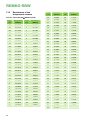
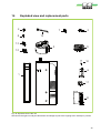
Assembly and operating instructions
REMKO RBW - Domestic hot water heat pump
RBW 300 PV / RBW 300 PV-S
Instructions for the Technician
0075-2015-06 Edition 2, en_GB
Read the instructions prior to performing any task!
Read these operating instructions carefully before commissioning / using this device!
These instructions are an integral part of the system and must
always be kept near or on the device.
Subject to modifications; No liability accepted for errors or misprints!
Installation and operating instructions (translation of the original)
Table of contents
1
Safety and usage instructions.............................................................................................................
1.1 General safety notes.......................................................................................................................
1.2 Identification of notes......................................................................................................................
1.3 Personnel qualifications..................................................................................................................
1.4 Dangers of failure to observe the safety notes................................................................................
1.5 Safety-conscious working...............................................................................................................
1.6 Safety notes for the operator...........................................................................................................
1.7 Safety notes for installation, maintenance and inspection..............................................................
1.8 Unauthorised modification and changes.........................................................................................
1.9 Intended use...................................................................................................................................
1.10 Warranty........................................................................................................................................
1.11 Transport and packaging..............................................................................................................
1.12 Environmental protection and recycling........................................................................................
4
4
4
4
4
4
5
5
5
5
5
6
6
2
Technical data.......................................................................................................................................
2.1 Unit data .........................................................................................................................................
2.2 Product data ...................................................................................................................................
2.3 Unit dimensions and designations of the pipe connections............................................................
7
7
8
9
3
Design and function............................................................................................................................
3.1 Domestic hot water heat pump, general.......................................................................................
3.2 Product description.......................................................................................................................
3.3 Corrosion protection......................................................................................................................
11
11
11
12
4
Assembly.............................................................................................................................................
4.1 System layout................................................................................................................................
4.2 General installation notes..............................................................................................................
4.3 Set-up............................................................................................................................................
12
12
13
13
5
Installation........................................................................................................................................... 16
6
Hydraulic connection.......................................................................................................................... 18
7
Electrical wiring...................................................................................................................................
7.1 General notes................................................................................................................................
7.2 Connection of the power PCB.......................................................................................................
7.3 Circuit diagrams............................................................................................................................
8
Commissioning................................................................................................................................... 23
9
Control logic........................................................................................................................................ 23
10
Operation............................................................................................................................................. 25
11
Care and maintenance........................................................................................................................ 43
12
Temporary shutdown.......................................................................................................................... 43
13
Troubleshooting and customer service............................................................................................ 44
13.1 Troubleshooting and customer service....................................................................................... 44
13.2 Resistances of the temperature sensors..................................................................................... 46
14
Exploded view and replacement parts ............................................................................................. 49
15
Index..................................................................................................................................................... 51
21
21
21
22
3
REMKO RBW
1
Safety and
usage instructions
1.1 General safety notes
Carefully read the operating manual before commissioning the units for the first time. It contains
useful tips and notes such as hazard warnings to
prevent personal injury and material damage.
Failure to follow the directions in this manual not
only presents a danger to people, the environment
and the system itself, but will void any claims for
liability.
Keep this operating manual and the refrigerant
data sheet near to the units.
1.2 Identification of notes
This section provides an overview of all important
safety aspects for proper protection of people and
safe and fault-free operation.The instructions and
safety notes contained within this manual must be
observed in order to prevent accidents, personal
injury and material damage.
Notes attached directly to the units must be
observed in their entirety and be kept in a fully
legible condition.
Safety notes in this manual are indicated by symbols. Safety notes are introduced with signal words
which help to highlight the magnitude of the danger
in question.
DANGER!
Contact with live parts poses an immediate
danger of death due to electric shock. Damage
to the insulation or individual components may
pose a danger of death.
DANGER!
This combination of symbol and signal word
warns of a situation in which there is immediate
danger, which if not avoided may be fatal or
cause serious injury.
WARNING!
This combination of symbol and signal word
warns of a potentially hazardous situation,
which if not avoided may be fatal or cause
serious injury.
4
CAUTION!
This combination of symbol and signal word
warns of a potentially hazardous situation,
which if not avoided may cause injury or material and environmental damage.
NOTICE!
This combination of symbol and signal word
warns of a potentially hazardous situation,
which if not avoided may cause material and
environmental damage.
This symbol highlights useful tips and recommendations as well as information for efficient
and fault-free operation.
1.3 Personnel qualifications
Personnel responsible for commissioning, operation, maintenance, inspection and installation must
be able to demonstrate that they hold a qualification which proves their ability to undertake the
work.
1.4 Dangers of failure to observe
the safety notes
Failure to observe the safety notes may pose a risk
to people, the environment and the units. Failure to
observe the safety notes may void any claims for
damages.
In particular, failure to observe the safety notes
may pose the following risks:
n The failure of important unit functions.
n The failure of prescribed methods of maintenance and repair.
n Danger to people on account of electrical and
mechanical effects.
1.5 Safety-conscious working
The safety notes contained in this manual, the
existing national regulations concerning accident
prevention as well as any internal company
working, operating and safety regulations must be
observed.
1.6 Safety notes for the operator
The operational safety of the units and components is only assured providing they are used as
intended and in a fully assembled state.
n The units and components may only be set up,
installed and maintained by qualified personnel.
n Protective covers (grille) over moving parts
must not be removed from units that are in
operation.
n Do not operate units or components with
obvious defects or signs of damage.
n Contact with certain unit parts or components
may lead to burns or injury.
n The units and components must not be
exposed to any mechanical load, extreme
levels of humidity or extreme temperature.
n Spaces in which refrigerant can leak sufficient
to load and vent. Otherwise there is danger of
suffocation.
n All housing parts and device openings, e.g. air
inlets and outlets, must be free from foreign
objects, fluids or gases.
n The units must be inspected by a service technician at least once annually. Visual inspections and cleaning may be performed by the
operator when the units are disconnected from
the mains.
1.7 Safety notes for installation,
maintenance and inspection
n Appropriate hazard prevention measures must
be taken to prevent risks to people when performing installation, repair, maintenance or
cleaning work on the units.
n The setup, connection and operation of the
units and its components must be undertaken
in accordance with the usage and operating
conditions stipulated in this manual and comply
with all applicable regional regulations.
n Local regulations and laws such as Water
Ecology Act must be observed.
n The power supply should be adapted to the
requirements of the units.
n Units may only be mounted at the points provided for this purpose at the factory. The units
may only be secured or mounted on stable
structures, walls or floors.
n Mobile units must be set up securely on suitable surfaces and in an upright position. Stationary units must be permanently installed for
operation.
n The units and components should not be operated in areas where there is a heightened risk
of damage. Observe the minimum clearances.
n The units and components must be kept at an
adequate distance from flammable, explosive,
combustible, abrasive and dirty areas or
atmospheres.
n Safety devices must not be altered or
bypassed.
1.8 Unauthorised modification
and changes
Modifications or changes to units and components
are not permitted and may cause malfunctions.
Safety devices may not be modified or bypassed.
Original replacement parts and accessories
authorised by the manufactured ensure safety. The
use of other parts may invalidate liability for
resulting consequences.
1.9 Intended use
Depending on the model, the equipment and the
additional fittings with which it is equipped is only
intended to be used as an air-conditioner for the
purpose of cooling or heating the air in an
enclosed room.
Any different or additional use shall be classed as
non-intended use. The manufacturer/supplier
assumes no liability for damages arising from such
use. The user bears the sole risk in such cases.
Intended use also includes working in accordance
with the operating and installation instructions and
complying with the maintenance requirements.
Under no circumstances should the threshold
values specified in the technical data be exceeded.
1.10
Warranty
For warranty claims to be considered, it is essential
that the ordering party or its representative complete and return the "certificate of warranty" to
REMKO GmbH & Co. KG at the time when the
units are purchased and commissioned.
The warranty conditions are detailed in the "General business and delivery conditions". Furthermore, only the parties to a contract can conclude
special agreements beyond these conditions. In
this case, contact your contractual partner in the
first instance.
5
REMKO RBW
1.11
Transport and packaging
The devices are supplied in a sturdy shipping container. Please check the equipment immediately
upon delivery and note any damage or missing
parts on the delivery and inform the shipper and
your contractual partner. For later complaints can
not be guaranteed.
WARNING!
Plastic films and bags etc. are dangerous
toys for children!
Why:
- Leave packaging material are not around.
- Packaging material may not be accessible to
children!
1.12
Environmental protection
and recycling
Disposal of packaging
All products are packed for transport in environmentally friendly materials. Make a valuable contribution to reducing waste and sustaining raw materials. Only dispose of packaging at approved
collection points.
Disposal of equipment and components
Only recyclable materials are used in the manufacture of the devices and components. Help protect
the environment by ensuring that the devices or
components (for example batteries) are not disposed in household waste, but only in accordance
with local regulations and in an environmentally
safe manner, e.g. using certified firms and recycling specialists or at collection points.
6
2
Technical data
2.1 Unit data
Series
RBW 300 PV
RBW 300 PV-S
Function
Domestic hot-water heating
System
Air / water heat pump
Drinking water tank enamelled, gross volume
l
Drinking water tank enamelled, net volume
l
Series 300
287
280
Auxiliary heater / rated output
kW
Series / 1.5
Usable limits, heating
°C
-7 to +40
Min./max. Water temperature
°C
38 / 60
Heating capacity with A7/W50
kW
1.8
COP per EN 255-3 / COP with A7/W50 1)
COP
3.7
COP per EN 16147 / COP with A7/W50 1)
COP
2.61
V / ~ / Hz
230 / 1/ 50
Electrical rated power consumption
kW
0.46
Max. rated power consumption
kW
2.06
Rated current consumption
A
8.92
Max. current consumption
A
9.0
Refrigerant / basic capacity
-- / kg
134A2) / 0.95
A slowacting
16
Sound power level/sound pressure 1m hemispherical
dB(A)
53/45
Max. airflow volume
m³/h
350
Min. flow volume
m³/h
175
Max. operating pressure
bar
7
Air duct connection
mm
145
Hydraulic connection, water-side
Inches
IG 3/4"
Condensate-drain socket
Inches
IG 1/2"
Max. permissible air-side pressure loss
Pa
50
Pipe length supply/exhaust duct max. (at 150 mm)
m
6/6
mm
650/1870/1920
Enclosure class
--
IP X1
Weight
kg
Power supply
Fuse protection prov. by the customer (p. outdoor unit)
Dimensions (diameter/height/tilt height)
1)
COP = coefficient of performance (heating capacity figure)
2)
Contains greenhouse gas according to Kyoto protocol, GWP 1975
136
141
For technical details regarding the integrated heat exchanger see overleaf.
7
REMKO RBW
Integrated heat exchanger
Series
RBW 300 PV
RBW 300 PV-S
m2
---
1.5
Inches (mm)
---
G 3/4" (19.05)
Solar heat exchanger
Heat exchanger connection
Information provided without guarantee! We reserve the right to make technical changes
within the framework of technical advancement.
2.2 Product data
Average-, Warmer-, and Colder condition
RBW 300
PV
Series
RBW 300
PV-S
Energy efficiency ratio
A
Load profile
XL
Hot water preparation energy efficiency (average1))
Annual electricity consumption (average1))
Factory temperature setting
Sound power level indoor
Hot water preparation energy efficiency (warmer2) / colder3))
Annual electricity consumption (warmer2) / colder3))
1)
Average condition = Moderate temperature periods
2)
Warmer condition = warm temperature periods
3)
Colder condition = cold temperature periods
8
%
115
kWh
1440
°C
50
dB(A)
57
%
115
kWh
1228 / 1622
2.3 Unit dimensions and designations of the pipe connections
145
145
1
6
11
2
7
8
8
12
1026
1195
4
1095
1435
1860
3
640
10
531
99
5
227
557
9
16,5
Fig. 1: Dimensions and designations of the pipe connections (data in mm)
1:
2:
3:
4:
5:
6:
Condensate drain Rp 1/2
Hot water outlet G 3/4"
False anode
Circulation G 3/4"
Cold water inlet G 3/4"
Connection safety valve
7:
8:
9:
10:
11:
12:
Heating-inlet heat exchanger G 3/4"
Immersion sleeve for probe temperature
Heating-return flow heat exchanger G 3/4"
Drainage G 3/4"
Overheating protector
Heating coil
We reserve the right to make changes within the framework of technical advancement!
9
REMKO RBW
Lid dimensions
632 mm
145 mm
450 mm
160 mm
145 mm
400 mm
Fig. 2: Lid dimensions
10
300 mm
3
Design and function
3.1 Domestic hot water heat pump,
general
Arguments in favour of the domestic hot water
heat pump from REMKO
n Hot water heat pump with advanced technology guarantees optimum and extremely
quiet operation.
n The powerful radial fan enables air guidance in
pipe lengths up to 12 m with Ø 150 mm.
n The thermostatic expansion valve and the
safety devices ensure optimum circuit functionality.
n The heart of the hot water heat pump: The
strong and durable condenser with oil cooler
and waste heat utilisation through suction gas
cooling.
n Large-area finned evaporator.
n The air connections enable a simple supply/
exhaust air installation at the assembly site.
n Environmentally friendly and non-flammable
safety refrigerant R134A.
n Enamelled quality hot water tank. Quality
assurance guarantees a long service life, sacrificial false anode for increased safety.
n Tube coil condenser ensures efficient heat
transfer and optimum safety.
n Internal smooth tube heat exchanger for the
connection of solar collectors or boilers.
n Electric heater, factory installed.
n Negligible maintenance costs.
Function of the hot water heat pump
The hot water heat pump utilises ambient air for
hot water preparation. The air is drawn in from
above with the aid of a fan, supplied to the evaporator and subsequently blown out again at the top.
The evaporator is so-called, because it evaporates
the refrigerant in the heat pump circuit. During
evaporation, heat is taken from the ambient air
drawn in, because this is warmer than the refrigerant in the evaporator. This means that heat can
be obtained from the air and transferred to the
refrigerant even at relatively low temperatures. The
refrigerant is compressed by the condenser, and
brought to a higher temperature level. This heat is
transferred to the drinking water via the tube coil
condenser. The cooled refrigerant, which is once
again liquid in state, is expanded in the expansion
valve, transported to the evaporator and is therefore able to absorb heat once again.
NOTICE!
The storage tank must be completely filled and
bled for initial commissioning.
NOTICE!
The heat-up phase may take some time,
depending on the filling water temperature and
air intake temperature.
The refrigerant circuit
The hot water heat pump operates according to
the Carnot process. The refrigerant circuit is filled
with refrigerant R134a in the factory, is highly efficient and guarantees optimum safety and efficiency in operation.
3.2 Product description
The Remko RBW 300 is a domestic hot water heat
pump with integrated enamelled hot water storage
tank. The storage tank has a volumetric capacity of
300 l. The RBW 300 is easy to install due to the
practical pipe connections and plug-in electric
wiring, e.g. in the basement, plant room or utility
room.
The Remko RBW 300 S is a domestic hot water
heat pump with an additionally integrated heat
exchanger with 1.5m2, for the connection of a solar
plant or another heat generator.
During pure heat pump operation, the max.
drinking water temperature is 60 °C. This means
that a high level of drinking water hygiene can be
guaranteed. With an increased demand for hot
water or high temperatures, it is possible to actuate
the 1.5 kW electric heating element.
11
REMKO RBW
3.3 Corrosion protection
The hot water tank is produced from enamelled
steel. This is designed for standard quality drinking
water. If drinking water with above-average
aggressive qualities is used (chloride content ³ 150
mg/l) then it is not possible to provide a guarantee
unless special protective measures are implemented.
NOTICE!
Check the false anode regularly and have this
replaced by your fitter if necessary. This is a
prerequisite for the guarantee!
NOTICE!
It is essential to replace the magnesium-false
anode if this exhibits a diameter of just 6-10
mm!
4
Assembly
4.1 System layout
b
A
3
2
4
D
B
a
1
C
Fig. 3: System layout
1:
2:
3:
4:
A:
12
Cold water inlet
Ambient air
Storage tank
Hot water
Compressor
B:
C:
D:
a:
b:
Condenser
Thermal expansion valve
Evaporator
Low refrigerant temperature
High refrigerant temperature
4.2 General installation notes
4.3 Set-up
DANGER!
Danger of death!
Only authorised specialist personnel are permitted to remove the front panel and the upper
cover plate once the power plug has been
unplugged, because contact with live parts
poses a danger of death!
WARNING!
The set-up of the heat pump may only be carried out by trained specialists.
n
n
n
n
NOTICE!
Never tilt the unit more than 15 degrees for an
extended period of time. The unit can be tipped
by a max. 60° for short-term transport only.
Proceed with caution when lifting and lowering
the unit. Horizontal storage or transportation is
not permissible!
n These instructions are to be observed when
installing the heat pump.
n The unit should be delivered as near as possible to the site of installation in its original
packaging in order to avoid transport damage.
n The unit is to be checked for visible signs of
transport damage. Possible faults are to be
reported immediately to the contractual partner
and the haulage company.
n Suitable sites for installation are to be selected
with regard to machinery noise and the set-up
process.
n Establish all electrical wiring in accordance
with the relevant DIN and VDE standards.
n The electrical power cables must always be
fastened to the electrical terminals in the
proper manner. Otherwise there is a risk of fire.
n Make sure that pipes carrying water do not
pass through living or sleeping areas.
n
n
n
n
n
The heat pump must be set up indoors.
A condensate drain must be available.
The heat pump must be set up horizontally.
Suitable installation sites are dry, clean, frostfree rooms with a level floor, which exhibit a
height of no less than 2.30 m.
The heat pump must be installed on a firm,
level surface.
The surface must possess sufficient loadbearing capacity for the weight of the heat
pump.
The heat pump is to be mounted in such a way
that sufficient space is available on all sides for
purposes of installation and maintenance.
In order to keep output losses to a minimum,
the heat pump should be set up as close as
possible to the hot water consumer.
If the supply and exhaust air from neighbouring
rooms is to be used, ensure that no positive or
negative pressure can build up in the rooms.
Use of a circulation system
It is not advisable to use a circulation system
because the loss per running metre of piping can
be approx. 25- 30 Watts. However, if such a
system is installed then a timer and a thermostat
should be installed with it.
NOTICE!
To avoid damage to the system, the installation
location must be dry, capable of carrying the
load and frost-free.
NOTICE!
Keep the hot water heat pump and lines free of
frost
13
REMKO RBW
Air connection
The air take-off point should be selected with consideration to a high average air temperature and
the requisite air volume of 350 m3/h. Air inlets and
outlets are at the top. In order to keep the air
resistance to a minimum, the air intake and
exhaust duct should be configured as straight as
possible, with a minimum smooth tube cross-section of Ø 150 mm. The entire tube length for the
intake and exhaust air should not be more than 12
m, whereby the installation of no more than 3 rightangled elbows is permitted. The entire tube length
must be reduced by 1 m with every additional
elbow. In order to prevent the discharge of condensate water, the air lines must be laid horizontally or
with a slight downward gradient towards the suction/blow-out openings, or the installation of an
evaporation pouch is required.
Fig. 4: Floor mounting
Air duct lines
Minimum distances
350
2500
n Suction and blow-out lines from smooth tube,
Ø 150 mm.
n The max. overall length of the pipe
(suction and exhaust air) is 12 m with a
max. 3 x 90° elbows
n The entire tube length must be reduced by 1 m
for every additional elbow!
n The pipes incl. accessories must be provided
by the customer (ventilation pipe produced
from plastic, aluminium or galvanised sheet
steel, etc.).
n The pressure loss must not exceed
a max. 50 kPa.
NOTICE!
350
350
Fig. 5: Minimum distances in mm
Suction air
The suction air must not be loaded with aggressive
substances (ammonia, sulphur, halogen, chlorine,
etc.)! This can cause the destr. of machine parts!
14
During operation of the domestic hot water
heat pump in the recirculation mode, the
volume must be at least 30 m3. (See Fig. 6 pictures A-C)
A
B
C
D
Fig. 6: Possible installations
A: Heating/hobby room (recirculation mode)
B: Laundry room (recirculation mode)
C: Storage/storeroom (recirculation mode)
D: Gym room
15
REMKO RBW
5
Installation
General notes
The hot water heat pump is a factory-tested unit.
Once the water connections have been professionally established, the storage tank has been filled
and the electrical connection (230 V/ 50 Hz) has
been established, it is possible to switch the unit
on.
WARNING!
The hot water heat pump must be connected
and put into operation exclusively by a certified
and authorised specialist!
It is possible to dispense with the use of a false
anode if the chloride content in the drinking
water is < 150 mg/l.
Always install a pressure reducer in the cold
water line.
Pressure reducer
Always install a pressure reducer in the cold water
supply line!
Safety valve
WARNING!
It is necessary to fill the unit with water before
the electrical wiring is connected!
Sanitary connection and assembly
NOTICE!
If using copper and galvanised steel tubes
always observe the sequence in the flow direction: Copper after galvanised steel!
Avoidance of heat losses
In order to minimise heat losses plan the water
lines as short as possible and include thermal insulation. Have the lines installed by a professional.
Sanitary installation
The direct connection with a stainless steel tank
must never be produced from copper or galvanised. If a stainless steel tank is connected with a
galvanised cold water line (with the requisite fittings or threaded connections) then a fine filter
must be fitted upstream of the stainless steel tank
in order to protect against rust particles, etc. Brass,
red brass, plastic and stainless steel are all suitable connection materials. If a stainless steel
storage tank is connected with a galvanised or
copper line then it is necessary to fit a red brass or
brass fitting between these parts.
16
The safety valve prevents positive pressure from
building and serves to drain off the excess water,
which occurs due to expansion of the storage tank
contents when heated.
n Only install a type-approved membrane safety
valve. This must be adjusted such that it safely
prevents the maximum permissible positive
operating pressure of the heat pump storage
tank - of 6 bar - from being exceeded by more
than 1 bar. The connection diameter of the
safety valve must be at least 1/2“. No shut-off
valve may be installed between the safety
valve and storage tank.
n The drain line downstream of the drainage
funnel for the safety valve must exhibit twice
the cross-section of the safety valve connection, it must not lead outdoors and must not be
blocked. Drainage should take place exclusively via the cold water connection or
drainage cock.
During the heating process, the expansion water
must visibly drip out of the safety valve drain (heatup time 4-7h!).
n The hot water distribution system should be
configured without circulation.
n The hot water lines must be thermally insulated
according to the local (municipal) regulations.
Charging with a second heat generator (solar,
combustible burner for solid fuel)
n The supply and return lines must be thermally
insulated by design, and must be connected
such that no return or single tube gravity circulation can arise with electric heating and the
circulation pump switched off.
n The expansion of the heating water must be
guaranteed at all times (also with electric
heating).
n Fit a bleeder at the top point in the hot water
line.
The hot water heat pump is fitted with a 1.3 m2
heating battery as standard. This enables connection with an existing heating system. The option
therefore exists of also heating the hot water with
the existing boiler. For this purpose, the heating
battery supply and return flow are connected with
the heating system.
NOTICE!
When connecting the hot water heat pump
with a boiler:
When operating the circulation pump, the powerful boiler circulation can result in the transport of heat from the hot water heat pump into
the boiler. In order to prevent this, fit a check
valve after the circulation pump of the heat
generator!
Condensate water drain
The cooling of the air in the evaporator results in
condensate water forming. The condensate drain
on the hot water heat pump must be transported
away from the heat pump with plastic pipes and an
uninterrupted flow of the condensate must be guaranteed. Depending on the humidity, up to approx.
0.25 l/h of condensate may arise.
The condensate drain must not be permanently
connected with a duct connection, and must be
designed and executed so that it is discharged
freely.
17
REMKO RBW
6
Hydraulic connection
Hydraulic connection drawings
All components and safety devices must be provided by the customer.
F
D
7
E
8
11
10
B
1
3
2
1
4
6
9
C
5
A
8
Fig. 7: Hydraulic connection drawings
A:
B:
C:
D:
E:
F:
1:
2:
3:
18
Cold water inlet
Inlet 2nd heat generator
Return flow 2nd heat generator
Condensate drain
Hot water outlet
Hot water
Shut-off valve
Storage tank recharging (by oil, gas or solar)
Flap valve
4:
5:
6:
7:
8:
9:
10:
11:
Immersion sleeve (for oil, gas or solar)
Storage tank emptying
Electric heating coil
Circulation pump
Flap valve
Safety valve, 6 bar
Safety temperature limiter
Magnesium anode
RBW hydraulic diagram 1
Functions: heating and hot water
This hydraulic diagram serves merely to assist in planning activities;
the hydraulic system on site must be planned and laid out by the installer!
1
2
3
4
A
5
B
40°
Fig. 8: Example 1 - hydraulic diagram RBW
A:
B:
1:
2:
RBW Heat pump
Oil-/ gas boiler
Cold water
Warm water
3: 1st mixed heating cycle
4: 2nd mixed heating cycle
5: Probe boiler (probe warm water)
19
REMKO RBW
RBW hydraulic diagram 2
Functions: heating and hot water
This hydraulic diagram serves merely to assist in planning activities;
the hydraulic system on site must be planned and laid out by the installer!
1
2
3
4
5
6
A
B
C
S 08
7
Fig. 9: Example 2 - hydraulic diagram RBW
A:
B:
C:
1:
2:
20
RBW Heat pump
Speicher
Oil-/ gas boiler
Cold water
Warm water
3:
4:
5:
6:
7:
Solar
1st mixed heating cycle
2nd mixed heating cycle
Pump solar
Solar changeover valve
40°
7
Electrical wiring
7.1 General notes
DANGER!
DANGER!
All electrical installation work must be done by
an electrician.
The wiring provided by the customer must comply
with the local regulations. The power supply to the
unit must comply precisely with the voltage and frequency stipulated in the technical data. Get in contact with the local energy supplier if incorrect mains
voltages require correction. Operation of a unit with
incorrect mains voltage constitutes misuse, which
is not covered by the guarantee.
7.2 Connection of the power PCB
Fig. 10: Connection of the power PCB
AC-N:
AI01:
AI02:
AI03:
AI04:
AI05:
OUT3
OUT4
OUT5
AC-N
OUT1
3
4
OUT2
HW200
CN1
CN2
12V
NET
GND
DI01
GND
DI02
GND
DI03
GND
DI04
GND
DI05
GND
DI06
GND
Attention
In order to avoid electric shocks and damage
to the unit, ensure that the electrical installation
has been carried out professionally prior to
establishing the electrical wiring (power plug
with 2 m cable to the socket provided by the
customer).
3
4
CN19
CN6
AI06:
CN1:
CN2:
CN6:
CN19:
DI01:
DI02:
DI03:
DI04:
DI05:
DI06:
12 V/NET/
GND:
OUT2(3):
OUT2(4):
GND
AI06
GND
AI05
GND
AI04
GND
AI03
GND
AI02
GND
AI01
OUT1(3):
OUT1(4):
OUT3:
OUT4:
OUT5:
Neutral conductor
Air suction temperature
Temperature storage below
Temperature storage above
Temperature evaporator (refrigerant)
Temperature suction pipe (refrigerant)
Probe collector
Transformer 1 - 230V
12V
/006
Not connected
Jumper
Jumper
Jumper
High pressure
Not connected
Contact photovoltaic (potential-free)
Power supply control panel
Electrical heating coil 230 V
Power supply
electrical heating coil 230 V
Compressor
Compressor power supply 230 V
4-way valve
High speed fan
Pump solar
21
REMKO RBW
7.3 Circuit diagrams
C2(2uF)
BLU
1
L
2
3
4
02
5
7
6
8
WHT
RED
COMP
BLK
CR
FM
C1
ORG
BLK
CC
CS
WHT
RED
EEV
5
OUT3
HT
OUT1
OUT4
E2V
1
2
N
3
4
HW200
OUT5
5
01
AC-N
7
N
6
GND
AI06
GND
AI05
GND
AI04
GND
AI03
GND
AI02
GND
AI01
OUT2
8
2 2
2
MTS
1
RESET
TC
4
3
SUT 6.8K
SUT
SUT
5K
CT
CT
CT
5K
TTT
TTT
TTT
5K
BTT
BTT
BTT
5K
AT
AT
AT
5K
3
12V
HP
Controller
RED BLU Y/G
L N
BRN BLU Y/G
1
1
2
230V~/50Hz
PV input
Fig. 11: Electrical drawings domestic hot water heat pump
1: Contact photovoltaic (potential-free)
C2(2uF)
K2
BLU
1
2
L
3
4
02
5
N
6
8
WHT
RED
COMP
BLK
7
CR
WHT
FM
BLK
CC
1
CS
C1
EEV
5
HT
OUT3
E2V
1
2
N
3
4
01
5
6
OUT1
OUT4
N
2
OUT5
7
8
MTS
1
RESET
3
RED BLU Y/G
L N
TC
3
OUT2
HW200
5
230V
230V
2
3
t
4
STT
STT
SUT
SUT
CT
CT
TTT
TTT
BTT
BTT
AT
AT
5K
5K
5K
5K
5K
HP
Controller
1
2
1
PV input
Fig. 12: Electrical drawings domestic hot water heat pump with solar connection
1: Contact photovoltaic (potential-free)
2: Solar pump
22
6
50K
12V
BRN BLU Y/G
230V~/50Hz
4
GND
AI06
GND
AI05
GND
AI04
GND
AI03
GND
AI02
GND
AI01
2 2
4
3
K2
AC-N
2
2
RED
3: Changeover valve
4: Probe collector
SUT
CT
TTT
BTT
AT
8
Commissioning
Before you switch on the domestic hot water
heat pump, ensure that
1.
the storage tank is filled with water.
2.
the electrical wiring exhibits 230V/50Hz.
3.
all connections have been correctly established.
9
Control logic
Compressor
1) Minimum switch-off time t=2 minutes
Following the request by the controller, the standstill time is a further 2 min.
1
A
t
CAUTION!
2
1
Ensure that a safety valve (6 bar) is correctly
connected to the cold water inlet at all times!
B
t
t
2
Fig. 13: Control logic switch-off time
A:
B:
1:
2:
Signal
Compressor
On
Off
2) Minimum switch-on time t=2 minutes
1
A
t
2
1
B
t
t
2
Fig. 14: Control logic switch-on time
A:
B:
1:
2:
Signal
Compressor
On
Off
3) Normal heating
1
B
2
P0-P1
P0
T1
Fig. 15: Control logic normal heating
B: Compressor
1: On
2: Off
23
REMKO RBW
Defrosting
1) Defrosting start
a) Run-time compressor min. parameter d03.
b) Min. temperature at the evaporator under d01.
2) Defrosting end
a) Evaporator temperature > d02 or max.
defrosting period d04 exceeded.
3) Evaporator fan off, 4-way changeover valve off.
A
B
C
D
Fig. 16: Control logic defrosting
A:
B:
C:
D:
24
Defrosting signal
Changeover valve
Compressor
Fan motor
10
Operation
Functions of the operating unit
A
B
C
D
E
F
Fig. 17: Operating unit keys
Key functions
A
- "ON/OFF" key
Press this key to switch the domestic hot water heat pump on or off
(hold key down for approx. 2 seconds).
B
- "MODE" key
The modes and parameters are selected using this
key. If you wish to reset the parameters to the factory setting, press this key for longer than 10 seconds.
C
- "Clock" key
E
- "Up" arrow key
Press this key to increase the setpoints.
F
- "Down" arrow key
Press this key to decrease the setpoints.
Press this key to set the time and date.
D
- "Electric heating element" key
Press this key to switch on the electric heating coil.
Activate the ventilation function by holding down
this key for 2 seconds.
25
REMKO RBW
18
19
1
2
3
4
5
6
17
11
7
10
8
9
16
15
21
20
14 13 12
Fig. 18: Symbols of the operating unit
Symbol functions
12
- Second
1
- Heating mode compressor and heating coil
13
- ° Celsius
2
- Economic heating mode, only compressor
14
- ° Fahrenheit
15
- Keyboard locked
1
+
2
- Automatic mode
3
- Holiday mode
4
- Invalid
5
- Recirculation operation
6
- Electric heating element
7
- Parameter selection
8
- Current temperature measured
9
- Timer "On"
10
- Timer "Off"
11
- Minute
26
16 - The unit is in standby once the temperature
has been reached
17
- Parameter code for setting the interface
18
- Water temperature storage tank, top
19
- Water temperature storage tank, bottom
20
- Time and date
21
- 1) Actual temperature
2) Parameter values when setting interface
Operation
Setting mode
Commissioning preparation
4 operating modes are available: Hybrid mode,
Economic mode, Automatic mode and Holiday
mode.
1.
After switching on the power supply the controller uploads the parameters for approx. 15
seconds.
2.
Ensure that the storage tank is filled with
water.
3.
In order to switch on the unit, touch the "On/
Off" switch for at least 0.5 seconds. The outside temperature measured then appears on
the display.
1: Hybrid mode
The water is heated in combination with the heat
pump and electric heating coil.
Unit operation
Fig. 20: Hybrid mode
2: Economic heating mode
5 sec.
The water is heated exclusively in heat pump
mode. The electric heating coil can be additionally
activated manually.
Fig. 21: Economic heating mode
Fig. 19: "On/Off" key
3: Automatic mode
The controller switches the heat pump and where
applicable the heating coil on, depending on the
ambient air (suction air).
Fig. 22: Automatic mode
27
REMKO RBW
4: Holiday mode
Operation
It is possible to select this mode in order to go on
holiday for a certain period of time. The heat pump
is off during this period. It is possible to program a
date of departure and a date of arrival.
Fig. 23: Holiday mode
Before leaving the system, switch the heat
pump to holiday mode. In order to have hot
water available upon your return, program the
switch-on point 1 day in advance of your
arrival.
Fig. 24: Operation
28
Setting the setpoint
NOTES
In the main menu (default screen) tap on the "Up"
(E) or "Down" (F) arrow keys.
1.
Once the setpoint temperature has been reached,
press the "Mode" key (B) in order to save the setpoint temperature, or press the "On/Off" key (A) in
order to cancel the setpoint setting.
If the "On/Off" key is pressed after the
values have been changed then the values
are not saved.
2.
If no key is pressed for 5 seconds after
changing the values then the controller
jumps to the main view and the settings are
saved.
Key lock
In order to lock the keys, press the "On/Off" key for
approx. 5 seconds. The "lock" symbol appears in
the display. No settings can be implemented in this
state. To unlock, press the "On/Off" key for approx.
5 seconds
or
5 sec.
or
Fig. 26: Key lock
or
NOTE
If the unit exhibits an alarm, the key lock is
released automatically
Fig. 25: Setting the setpoint
29
REMKO RBW
Electric heating element (heating coil)
Recirculation operation
Irrespective of which operating mode has been set,
the heating coil can be activated. In order to do so,
confirm the "Electric heating element" key (D). The
symbol appears in the display to indicate that the
heating coil is active. Upon reaching the target
temperature, the heating coil switches off automatically.
In recirculated air operation the device RBW 300
PV has two fan speeds and the unit RBW 300 PVS are only one (the middle) fan speed available.
The recirculation operation can be used in order to
ventilate the connected room, without the heat
pump (compressor) being in operation. To do so,
press the "Electric heating element" key (D) for
approx. 2 seconds. The fan symbol appears in the
display. It is possible to select 2 fan stages (only
by the device RBW 300 PV). In order to implement
a setting press the "Electric heating element" key
(D) for 2 sec.
2 sec.
Fig. 27: Electrical heating element - HP is on
2 sec.
2 sec.
Fig. 29: Recirculation operation
Fig. 28: Electrical heating element - HP is off
30
Setting the time
In order to set the time, press the clock symbol. When the time flashes, set the time using the arrow keys. In
order to save, press the "Mode" key (B). Then set the date.
or
or
or
A
B
or
C
D
Fig. 30: Setting the time
A: To set the year value proceed precisely as
described above.
B: If the "On/Off" key (A) is pressed during programming, the values are not saved and the
main menu is displayed once more.
C: If no settings are implemented for 5 seconds, the
values are saved and the main menu is displayed.
D: In order to check the date press on the "CLOCK"
key (C).
31
REMKO RBW
Time program
Possibility 2
To set the daily program, proceed as follows:
Possibility 1
2 sec.
2 sec.
2 sec.
2 sec.
2 sec.
Fig. 32: Time program - setting possibility 2
Fig. 31: Time program - setting possibility 1
32
Example of a daily program setting - switch on at 16:30 hrs
2 sec.
or
or
A
B
C
Fig. 33: Time program - example
A: Press the "CLOCK" key (C) in order to access
time program 1, settings are implemented as
described.
B: If no settings are implemented for 5 seconds, the
values are saved and the main menu is displayed.
C: If the "Hours/minutes" display flashes and the
"On/Off" key (A) is pressed, you will access the
main menu directly without saving the values.
Deactivating the set time program
2 sec.
Fig. 34: Deactivating the time program
33
REMKO RBW
Setting the holiday program
Press the "Mode" key (B) until the "Holiday mode" symbol (3) appears.
Example: Start the program on the 27th September.
2 sec.
or
A
B
5 sec.
C
Fig. 35: Holiday mode
A: Press the "Clock" key (C) in order to save your
entry.
B: Wait 5 seconds and your settings will be implemented.
C: Press the "On/Off" key (1) in order to return
directly to the main display.
NOTES
1.
Switch the unit off before going on holiday and set the date upon which the heat pump should
start up again. It is not necessary to switch it on. The unit will switch itself on automatically on
the set date.
2.
When the unit switches on, the symbols continue to be displayed in the main display, e.g.
"OFF". The display information is deleted at 0:00 hrs.
3.
The heat pump is started at 0:00 hrs.
34
Parameter configuration
Main menu
Main display: In order to access the parameter level, proceed as follows:
10 sec.
or
or
or
B
A
or
Fig. 36: Configuration of the parameters - expert level
A: The steps for changing other parameter values
are the same as with the parameter "do2".
B: Confirm the "Mode" key (B) in order to save your
setting and press the "On/Off" key to return to
the main menu.
NOTES
1.
If, after changing the values, the "On/Off" key is pressed whilst the parameter flashes, the
values will not be saved and it will jump to the top parameter.
2.
After saving the settings via the "Mode" key it is possible to return to the main menu by
pressing the "On/Off" key.
3.
After 20 seconds the set values will be saved and the display will show the main screen.
35
REMKO RBW
Activating the legionella function
Main display: In order to access the parameter level, proceed as follows:
10 sec.
or
or
or
or
Fig. 37: Activating the legionella function
g03: The steps for changing other parameter values
are the same as with the parameter "d02".
g04: Confirm the "Mode" key (B) in order to save
your setting and press the "On/Off" key to
return to the main menu.
The corresponding parameters, see Items 14-17 in figure Ä ‘Parameter’ on page 39
NOTES
1.
If, after changing the values, the "On/Off" key is pressed whilst the parameter flashes, the
values will not be saved and it will jump to the top parameter.
2.
After saving the settings via the "Mode" key it is possible to return to the main menu by
pressing the "On/Off" key.
3.
After 20 seconds the set values will be saved and the display will show the main screen.
36
Activating the solar function
If the REMKO RBW domestic hot water heat pump is operated in conjunction with a thermal solar plant,
please note the following:
n ZTo operate the heat pump in conjunction with max.7.5 m² solar collector surface, once the hydraulic
connection is established, it is also necessary to connect the collector probe included in the scope of
delivery. To do so, use the appropriate measuring point on your collector surface and connect the probe
to the connection Terminal 4 (Fig. 38). The solar collector pump is installed on Terminal 2.
n Then remove the resistor which this connection is already equipped with. This resistor should remain
with the unit, to ensure emergency operation in the event of a potential fault. If the REMKO RBW
domestic hot water heat pump is operated without the probe or resistor, an error is shown on the display.
Once installation of the thermal solar plant is complete and the collector probe has been connected, the
system is ready for operation. To optimise the installed system, it is also necessary to adjust the following
parameters on your system.
Code
ParaValue
meter
No.
Description
30
Used storage tank probe solar
n01
0
0-bottom/1-top
31
Min. run-time solar pump
n02
15 min
1-30 min
32
Start temperature difference solar
n03
5°C
0~20 K
33
Night reduction
n04
0/no
0-no/1-yes
34
Start time night reduction
n05
00 h
00~23 h
35
End time night reduction
n06
6h
00~23 h
36
Start temperature night reduction
n07
70°C
40~90°C
37
End temperature night reduction
n08
10°C
1~40°C
38
Max. storage tank temperature for the solar changeover valve
n09
70°C
50~90°C
39
Max. storage tank temperature solar pump stop
n10
70°C
50~90°C
40
Solar pump operation storage tank temperatureindependent
n11
0/no
0-no/1-yes
41
Start collector temperature solar pump
r01
55°C
10~60°C
n
r
Range
To adjust the parameters, perform the steps already described for configuring and activating the legionella
function in the relevant parameter menus.
Solar changeover valve
In order to increase solar yield, you have the option to use a changeover valve to charge an additional
storage tank (see example Fig. 8)
Description
Max. storage tank temperature for the solar changeover
valve
Code
n
ParaValue
meter
n10
70°C
Range
50~90°C
To adjust the parameters for activating the changeover valve, perform the steps already described for activating the solar function in the relevant parameter menus.
37
REMKO RBW
C2(2uF)
K2
BLU
1
2
L
3
4
02
5
N
6
8
WHT
RED
COMP
BLK
7
CR
WHT
FM
BLK
CC
1
CS
C1
EEV
5
HT
OUT3
E2V
1
2
N
3
4
01
5
6
OUT1
OUT4
N
2
OUT5
7
8
2
1
RESET
3
RED BLU Y/G
L N
TC
3
OUT2
HW200
5
6
230V
230V
2
3
50K
t
4
STT
STT
SUT
SUT
CT
CT
TTT
TTT
BTT
BTT
AT
AT
5K
5K
5K
5K
5K
SUT
CT
TTT
BTT
AT
HP
12V
Controller
BRN BLU Y/G
1
230V~/50Hz
4
GND
AI06
GND
AI05
GND
AI04
GND
AI03
GND
AI02
GND
AI01
2 2
4
3
K2
AC-N
MTS
2
RED
2
1
PV input
Fig. 38: Electrical drawings domestic hot water heat pump with solar connection
1: Contact photovoltaic (potential-free)
2: Solar pump
3: Changeover valve
4: Probe collector
Activating the PV function
To operate the REMKO RBW domestic hot water heat pump in conjunction with a photovoltaic system, you
have the option to use the potential-free contact Terminal 1 (Fig. 38) .
Once installation of the thermal solar plant is complete and the collector probe has been connected, the
system is ready for operation. To optimise the installed system, the following parameters must also be
adjusted on your system.
Description
Setpoint with PV yield
38
Code
r
ParaValue
meter
r14
45°C
Range
10-60°C
Parameter
Parameter list (expert level)
No.
Description
1
Factory setting
2
Factory setting
3
Factory setting
4
Factory setting
5
Factory setting
6
Code
/
ParaValue
meter
Range
/01
/02
C01
0
C02
5°C
C03
-1°C
Factory setting
C04
5°C
7
Start defrost temperature (evaporator)
d01
-3°C
-30~0°C
8
End defrost temperature (evaporator)
d02
13°C
2~30°C
9
Time between defrosts
d03
45 min
30~90 min
10
Max. defrosting period
d04
8 min
1~12 min
11
Min. defrosting period Eco defrosting (recirculation
defrosting)
d05
3 min
1~10 min
12
Defrosting mode 1 = recirculation, 2 = heat gas
d06
0
0~2
13
Ambient temp. at start of heat gas defrosting
d07
4°C
-10~20°C
14
Setpoint for legionella function
g01
60°C
30~70°C
15
Duration of legionella function
g02
0 min
0~90 min
16
Time start of legionella function
g03
0h
0~23 h
17
Time interval (day) of legionella function
g04
7 days
7~99 days
18
El. expansion valve mode
E01
1
Factory setting
19
Overheating temperature
E02
5°C
Factory setting
20
Expansion valve starting position
E03
240
Factory setting
21
Expansion valve minimale position
E04
100
Factory setting
22
Expansion valve position defrost mode
E05
480
Factory setting
23
Automatic restart after power failure
H01
1
0-no/1-yes
24
Activation kitchen mode
H02
0
0-no/1-yes
25
Heat source (air)
H03
0
Factory setting
26
Inlet time to commissioning
H04
1 min
Factory setting
27
Cooling function
H05
0
Factory setting
28
Time cooling function
H06
1,0
Factory setting
29
Temperature unit
H07
0
0-°C/1-F
C
d
g
E
H
39
REMKO RBW
Parameter list (expert level) - continued
Description
30
Used storage tank probe solar
n01
0
0-bottom/1-top
31
Min. run-time solar pump
n02
15 min
1-30 min
32
Start temperature difference solar
n03
5°C
0~20 K
33
Night reduction
n04
0/no
0-no/1-yes
34
Start time night reduction
n05
00 h
00~23 h
35
End time night reduction
n06
6h
00~23 h
36
Start temperature night reduction
n07
70°C
40~90°C
37
End temperature night reduction
n08
10°C
1~40°C
38
Max. storage tank temperature for the solar changeover valve
n09
70°C
50~90°C
39
Max. storage tank temperature solar pump stop
n10
70°C
50~90°C
40
Solar pump operation storage tank temperatureindependent
n11
0/no
0-no/1-yes
41
Start collector temperature solar pump
r01
55°C
10~60°C
42
Setpoint kitchen mode
r02
45°C
40~48°C
43
Hysteresis setpoint HW water
r03
5°C
1~20 K
44
Parallel operation heat pump/heating coil
r04
0/nein
0-no/1-yes
45
Switch-on temperature elec. Heating coil
r05
55°C
30~90°C
46
Switch-on delay elec. Heating coil
r06
200 min
0~450 min
47
Elec. heating coil replaces compressor
r07
0
0-no/1-yes
48
Lower heat pump usable limit
r08
0°C
-20~10°C
49
Bivalence point elec. heating coil without delay
r09
10°C
0~30°C
50
Bivalence point elec. heating coil with time delay r06
r10
25°C
10~40°C
51
Factory setting
r11
60 s
0~255 s
52
Lower heat pump emergency stop usable limit
r12
-5°C
-5~-30°C
53
Heat limit kitchen mode
r13
56°C
50~56°C
54
Setpoint with PV yield
r14
45°C
10-60°C
55
Removes on/off switch status
S01
Status
CL/OP
56
OHP switch (over heat protection) condenser
S02
Status
CL/OP
57
Not assigned
58
Error output high pressure alarm switch status
S04
Status
CL/OP
59
Switch status elec. Heating coil
S05
Status
CL/OP
60
Not assigned
40
Code
ParaValue
meter
No.
n
r
S
Range
Parameter list (expert level) - continued
Code
ParaValue
meter
No.
Description
61
Ambient temperature
t01
Measured
value
-9~99°C
62
Storage tank temperature, lower
t02
Measured
value
-9~99°C
63
Storage tank temperature, upper
t03
Measured
value
-9~99°C
t
Range
64
Evaporator temperature
t04
Measured
value
-9~99°C
65
Suction gas temperature
t05
Measured
value
-9~99°C
66
Collector temperature
t06
Measured
value
-9~99°C
67
Compressor status
O01
Status
On/Off
68
Electric heating coil status
O02
Status
On/Off
69
Solenoid valve defrost
O03
Status
On/Off
70
Fan speed low
O04
Status
On/Off
71
Fan speed high/ circulation pump/ solar pump
O05
Status
On/Off
72
Operation circulation pump/solar pump
O06
Status
On/Off
73
EEV position
O07
Status
0~500
ParaValue
meter
Range
O
Parameter list (operator level)
No.
Description
1
Start defrost temperature (evaporator)
d01
-3°C
-30°C~0°C
2
End defrost temperature (evaporator)
d02
13°C
2~30°C
3
Time between defrosts
d03
45 min
30~90 min
4
Max. defrosting period
d04
8 min
1~12 min
5
Duration of legionella function
g02
0 min
0~90 min
6
Time start of legionella function
g03
0h
0~23 h
7
Time interval (day) of legionella function
g04
7D
7~99 days
8
Max. storage tank temperature solar pump stop
n10
70°C
50~90°C
9
Switch-on delay electr. heating coil
r06
200 min
0~450 min
41
REMKO RBW
Parameter description
Parameter
Designation
Description
d01
Start defrost temperature (evaporator)
If the evaporator temperature is < d01 then the
defrosting process starts
d02
End defrost temperature (evaporator)
If the evaporator temperature is > d02 then the
defrosting process ends
d03
Time between defrosts
This is the min. run-time of the heat pump
between 2 defrosting processes
d04
Max. defrosting period
Once the set time d04 lapses, defrosting ends
g02
Duration of legionella function
Time of the legionella function
g03
Time start of legionella function
The legionella function starts at this time
g04
Time interval (day) of legionella function
The legionella function is activated at this
interval (number of days)
n10
If the storage tank temperature is higher than
n10, the solar pump r06 stops: Switch-on delay
Max. storage tank temperature solar pump stop electrical heating coil. Upon exceeding the set
run-time r06, the electrical heating coil is
switched on
42
11
Care and maintenance
Regular care and maintenance guarantee troublefree operation and a long service life of the heat
pump.
n Check the electrical wiring
n Empty the storage tank for a heat pump shutdown. Risk of freezing!
n We recommend cleaning the storage tank regularly
n Check the function of sacrificial anode regularly
n We recommend setting the hot water temperature as low as possible, in order to ensure the
most effective operation possible
n Check all parts for pressure resistance and
leak-tightness. Check the refrigerant volume
regularly
n To perform the statutory seal test where applicable, it is necessary to arrange an annual
maintenance contract with an appropriate specialist firm.
n In the air intake of a basement laundry drying,
filters should be provided and should be monitored monthly. Also note the maximum pressure loss.
12
Temporary shutdown
The system may not be switched off at the mains
power supply even if the heating system is not
used for heating purposes over an extended period
(e.g. holidays)!
n The system is to be switched to "Stand-by"
mode during temporary shutdowns.
n Heating phases can be programmed for the
duration of the period of absence.
n The previous operating mode has to be
switched back on when the shutdown phase is
over.
n Changing the operating mode is described in
the "Operation" chapter.
NOTICE!
In "Standby" , the heat pump is in standby
mode. Of the entire system, only the frost-protection function s activated.
43
REMKO RBW
13
13.1
Troubleshooting and customer service
Troubleshooting and customer service
The unit has been manufactured using state-of-the-art production methods and has been tested several
times to ensure that it works properly. However, in the event that malfunctions should occur, the unit should
be checked against the list below. Please inform your dealer if the unit is still not working correctly after all of
the functional checks have been performed.
Fault description
Cause
Remedy
System does not function
Power supply correct?
Switch electricity off/on and check
voltage
Cable connections correct?
Check connections and replace if necessary
Fuse correct?
Check fuses and replace if necessary
Excess refrigerant
Refill
Condenser too hot
Reduce temperature in the storage
tank
Refrigerant level low
Check circuit for leaks
High pressure fault
Low pressure alarm
2. Refrigerant filter/capillary blocked Replace filter or capillary tube
Suction air temperature too cold/not Check air supply/temperature
present
No hot water being supplied Shut-off cocks for water supply
closed
Display remains dark
44
Open shut-off cocks
Water pressure too low
Increase water pressure
Safety temperature limiter has triggered
Reduce the temperature in the storage
tank
Error codes and their meanings
Code Error description
Cause
Remedial measures
Defective or short-circuited.
Plug-in contact not correct
Check probe resistance.
Replace probe
P01
Probe, storage tank bottom,
defective
P02
Probe, storage tank top, defective
P034
Probe, collector defective
P04
Probe, ambient air defective
P05
Probe, evaporator defective
P07
Probe, suction pipe defective
E01
High pressure fault
Refrigerant pressure is too
high, pressure switch has triggered
Check pressure, water temperature too high
E02
Low pressure alarm
Refrigerant pressure is too low,
pressure switch has triggered
Check pressure, refrigerant
deficiency
E03
Overheating error
Water level too low
Check water level
E08
Communication fault
Communication error between
Cable connection, check plugoperating unit and motherboard in contacts
45
REMKO RBW
13.2
Resistances of the
temperature sensors
NTC R-T Table (R25=5KW B25/50=3470K)
Temp.
(°C)
Resistance
(KOhm)
Temp.
(°C)
Resistance
(KOhm)
32
3.8349
67
1.1771
33
3.6955
68
1.1413
34
3.5620
69
1.1068
Temp.
(°C)
Resistance
(KOhm)
Temp.
(°C)
Resistance
(KOhm)
-30
63.7306
1
13.6017
35
3.4340
70
1.0734
-29
60.3223
2
13.0057
36
3.3113
71
1.0412
-28
57.1180
3
12.4393
37
3.1937
72
1.0100
-27
54.1043
4
11.9011
38
3.0809
73
0.9800
-26
51.2686
5
11.3894
39
2.9727
74
0.9509
-25
48.5994
6
10.9028
40
2.8688
75
0.9228
-24
46.0860
7
10.4399
41
2.7692
76
0.8957
-23
43.7182
8
9.9995
42
2.6735
77
0.8695
-22
41.4868
9
9.5802
43
2.5816
78
0.8441
-21
39.3832
10
9.1810
44
2.4934
79
0.8196
-20
37.3992
11
8.8008
45
2.4087
80
0.7959
-19
35.5274
12
8.4385
46
2.3273
81
0.7730
-18
33.7607
13
8.0934
47
2.2491
82
0.7508
-17
32.0927
14
7.7643
48
2.1739
83
0.7293
-16
30.5172
15
7.4506
49
2.1016
84
0.7086
-15
29.0286
16
7.1513
50
2.0321
85
0.6885
-14
27.6216
17
6.8658
51
1.9656
86
0.6690
-13
26.2913
18
6.5934
52
1.9015
87
0.6502
-12
25.0330
19
6.3333
53
1.8399
88
0.6320
-11
23.8424
20
6.0850
54
1.7804
89
0.6144
-10
22.7155
21
5.8479
55
1.7232
90
0.5973
-9
21.6486
22
5.6213
56
1.6680
91
0.5808
-8
20.6380
23
5.4048
57
1.6149
92
0.5647
-7
19.6806
24
5.1978
58
1.5636
93
0.5492
-6
18.7732
25
5.0000
59
1.5142
94
0.5342
-5
17.9129
26
4.8108
60
1.4666
95
0.5196
-4
17.0970
27
4.6298
61
1.4206
96
0.5055
-3
16.3230
28
4.4566
62
1.3763
97
0.4919
-2
15.5886
29
4.2909
63
1.3336
98
0.4786
-1
14.8913
30
4.1323
64
1.2923
99
0.4658
0
14.2293
31
3.9804
65
1.2526
100
0.4533
66
1.2142
46
NTC R-T Table (R25=50.000KW B25/50=3950K)
Temp.
(°C)
Resistance
(KOhm)
Temp.
(°C)
Resistance
(KOhm)
Temp.
(°C)
Resistance
(KOhm)
Temp.
(°C)
Resistance
(KOhm)
28
43.818
63
11.182
-40
2009.2
-6
232.60
29
41.956
64
10.799
-39
1869.0
-5
220.13
30
40.185
65
10.431
-38
1739.6
-4
208.40
31
38.500
66
10.078
-37
1620.2
-3
197.38
32
36.896
67
9.7393
-36
1509.8
-2
187.02
33
35.368
68
9.4134
-35
1407.8
-1
177.27
34
33.913
69
9.1002
-34
1313.5
0
168.10
35
32.527
70
8.7991
-33
1226.2
1
159.46
36
31.206
71
8.5096
-32
1145.3
2
151.32
37
29.947
72
8.2313
-31
1070.4
3
143.66
38
28.746
73
7.9637
-30
1001.0
4
136.43
39
27.600
74
7.7061
-29
936.58
5
129.62
40
26.507
75
7.4584
-28
876.76
6
123.19
41
25.464
76
7.2199
-27
821.21
7
117.12
42
24.468
77
6.9904
-26
769.58
8
111.39
43
23.517
78
6.7694
-25
721.58
9
105.98
44
22.608
79
6.5566
-24
676.92
10
100.87
45
21.740
80
6.3515
-23
635.35
11
96.040
46
20.911
81
6.1541
-22
596.63
12
91.470
47
20.118
82
5.9639
-21
560.55
13
87.148
48
19.359
83
5.7805
-20
526.92
14
83.057
49
18.634
84
5.6037
-19
495.54
15
79.185
50
17.940
85
5.4333
-18
466.26
16
75.519
51
17.276
86
5.2690
-17
438.91
17
72.045
52
16.641
87
5.1105
-16
413.37
18
68.754
53
16.032
88
4.9576
-15
367.69
19
65.634
54
15.450
89
4.8104
-14
367.16
20
62.676
55
14.892
90
4.6678
-13
346.26
21
59.870
56
14.357
91
4.5304
-12
326.70
22
57.207
57
13.845
92
4.3978
-11
308.38
23
54.679
58
13.353
93
4.2690
-10
291.22
24
52.279
59
12.882
94
4.1462
-9
275.13
25
50.000
60
12.430
95
4.0268
-8
260.05
26
47.834
61
11.997
96
3.9114
-7
245.89
27
45.775
62
11.581
97
3.8000
47
REMKO RBW
Temp.
(°C)
Resistance
(KOhm)
Temp.
(°C)
Resistance
(KOhm)
98
3.6923
110
2.6457
99
3.5887
111
2.5756
100
3.4876
112
2.5077
101
3.3903
113
2.4420
102
3.2978
114
2.3783
103
3.2052
115
2.3166
104
3.1172
116
2.2568
105
3.0320
117
2.1989
106
2.9497
118
2.1427
107
2.8699
119
2.0882
108
2.7927
120
2.0354
109
2.7180
48
14
Exploded view and replacement parts
4
5
7
3
14
13
2
9
12
10
6
1
11
8
Fig. 39: Exploded view of the unit
We reserve the right to modify the dimensions and design as part of the ongoing techn. developm. process
49
REMKO RBW
Spare parts list
No.
Designation
RBW 300 PV
RBW 300 PV-S
From serial number:
1422F...
1423F...
1
Casing, front
1110737
1110737
2
Casing, top
1110738
1110738
3
Operating unit
1110739
1110739
4
Solenoid valve
1110740
1110740
5
High pressure switch
1110741
1110741
6
Compressor
1110742
1110742
7
Thermostatic expansion valve
1110743
1110743
8
Heat exchanger
1110754
1110754
9
Fan blade
1110747
1110747
10
Compressor capacitor 15nF
1110748
1110748
11
Fan motor
1110749
1110749
12
Motherboard
1110750
1110750
13
Safety temperature limiter
1110760
1110760
14
Electrical heting coil 1,5 kW
1110761
1110761
15
Panel control unit
1110763
1110763
16
Capacitor fan motor 2nF
1110762
1110762
When ordering spare parts, please always state the EDP number, unit number and unit type
(see name plate)!
Spare parts not illustrated
No.
Designation
RBW 300 PV
RBW 300 PV-S
Transformer
1110764
1110764
Magnesium anode
1110744
1110744
Probe, suction pipe T5
1110745
1110745
Probe, air suction T1
1110746
1110746
Probe, water inlet T2
1110751
1110751
Probe, water outlet T3
1110752
1110752
---
1110755
1110753
1110753
Collector sensor T6
Probe, heat exchanger T4
When ordering spare parts, please always state the EDP number, unit number and unit type
(see name plate)!
50
15
Index
A
Ordering spare parts . . . . . . . . . . . . . . . . . . . . . 50
Average condition . . . . . . . . . . . . . . . . . . . . . . . . 8
Avoid heat losses . . . . . . . . . . . . . . . . . . . . . . . 16
P
C
Charging with a second heat generator . . . . . . . 16
Circuit diagrams . . . . . . . . . . . . . . . . . . . . . . . . 22
Colder condition . . . . . . . . . . . . . . . . . . . . . . . . . 8
Commissioning . . . . . . . . . . . . . . . . . . . . . . . . . 23
Condensate water drain . . . . . . . . . . . . . . . . . . 17
Connection of the power PCB . . . . . . . . . . . . . . 21
Control logic . . . . . . . . . . . . . . . . . . . . . . . . . . . 23
COP . . . . . . . . . . . . . . . . . . . . . . . . . . . . . . . . . . 7
Corrosion protection . . . . . . . . . . . . . . . . . . . . . 12
D
Disposal of equipment . . . . . . . . . . . . . . . . . . . . . 6
E
Electrical drawings . . . . . . . . . . . . . . . . . . . . . . 22
Electrical wiring . . . . . . . . . . . . . . . . . . . . . . . . . 21
Environmental protection . . . . . . . . . . . . . . . . . . . 6
F
False anode . . . . . . . . . . . . . . . . . . . . . . . . . . . 12
Function of the hot water heat pump . . . . . . . . . 11
Functions of the operating unit . . . . . . . . . . . . . 25
H
Heating capacity . . . . . . . . . . . . . . . . . . . . . . . . . 7
Hydraulic connection . . . . . . . . . . . . . . . . . . . . . 18
Hydraulic connection drawings . . . . . . . . . . . . . 18
I
Installation . . . . . . . . . . . . . . . . . . . . . . . . . . . . . 16
Intended use . . . . . . . . . . . . . . . . . . . . . . . . . . . . 5
L
Lid dimensions . . . . . . . . . . . . . . . . . . . . . . . . . 10
M
Magnesium-false anode . . . . . . . . . . . . . . . . . . 12
Minimum distances . . . . . . . . . . . . . . . . . . . . . . 14
O
Pipe connections . . . . . . . . . . . . . . . . . . . . . . . . . 9
Power PCB, connections . . . . . . . . . . . . . . . . . 21
Pressure reducer . . . . . . . . . . . . . . . . . . . . . . . . 16
Product description . . . . . . . . . . . . . . . . . . . . . . 11
Propellant according to Kyoto Protocol . . . . . . . . 7
R
Resistances
Temperature sensors . . . . . . . . . . . . . . . 46, 47
S
Safety
Dangers of failure to observe the safety
notes . . . . . . . . . . . . . . . . . . . . . . . . . . . . . . . 4
General . . . . . . . . . . . . . . . . . . . . . . . . . . . . . 4
Identification of notes . . . . . . . . . . . . . . . . . . . 4
Notes for inspection . . . . . . . . . . . . . . . . . . . . 5
Notes for installation . . . . . . . . . . . . . . . . . . . . 5
Notes for maintenance . . . . . . . . . . . . . . . . . . 5
Personnel qualifications . . . . . . . . . . . . . . . . . 4
Safety notes for the operator . . . . . . . . . . . . . 5
Safety-conscious working . . . . . . . . . . . . . . . . 4
Unauthorised modification . . . . . . . . . . . . . . . 5
Unauthorised replacement part manufacture . 5
Safety valve . . . . . . . . . . . . . . . . . . . . . . . . . . . 16
Sanitary connection . . . . . . . . . . . . . . . . . . . . . . 16
Sanitary installation . . . . . . . . . . . . . . . . . . . . . . 16
Set-up . . . . . . . . . . . . . . . . . . . . . . . . . . . . . . . . 13
Symbole . . . . . . . . . . . . . . . . . . . . . . . . . . . . . . 26
Symbolfunktionen der Bedieneinheit . . . . . . . . 26
System layout . . . . . . . . . . . . . . . . . . . . . . . . . . 12
T
Temperature sensors
Resistances . . . . . . . . . . . . . . . . . . . . . . 46, 47
U
Unit description . . . . . . . . . . . . . . . . . . . . . . . . . 11
Unit dimensions . . . . . . . . . . . . . . . . . . . . . . . . . 9
W
Warmer condition . . . . . . . . . . . . . . . . . . . . . . . . 8
Warranty . . . . . . . . . . . . . . . . . . . . . . . . . . . . . . . 5
Operating unit . . . . . . . . . . . . . . . . . . . . . . . . . 25
51
REMKO RBW
52
53
REMKO RBW
54
REMKO INTERNATIONAL
… and also right in your neighbourhood!
Make use of our experience and advice
REMKO GmbH & Co. KG
Air conditioning and heating technology
Im Seelenkamp 12
Postfach 1827
Telephone
Telefax
E-mail
Website
D-32791 Lage
D-32777 Lage
+49 52 32 6 06-0
+49 52 32 6 06-2 60
[email protected]
www.remko.de
Distribution
REMKO offers not just a well
established sales network both
nationally and internationally, but
also has exceptionally highlyqualified sales specialists.
REMKO field staff are more than
just sales representatives: above
all, they must act as advisers to
our customers in air conditioning
and heating technology.
SFlbCustomer Service
Our equipment operates
precisely and reliably. However,
in the event of a fault, REMKO
customer service is quickly at
the scene. Our comprehensive
network of experienced dealers
always guarantees quick and
reliable service.
We reserve the right to make technical changes, and provide no guarantee as to the accuracy of this data!
Consulting
Thanks to intensive training,
our consultants are always
completely up-to-date in terms
of technical knowledge. This has
given us the reputation of being
more than just an excellent,
reliable supplier:
REMKO, a partner
helping you find solutions to
your problems.