1
Operating Instructions
Single Loop Temperature Controller
ETR 45 & ETR 46
Rev. 1.00.07
07/2015
Translation of original
operating instructions
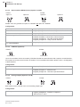
Quick start-up
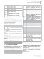
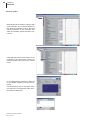
The temperature controller is ready for use. One control zone for one heater and one thermocouple for measurement of the actual value is set up for operation. The start-up of the control zone can be done in a few steps. (*) see
chapter ÓDisplay Loc)
ETR45
ETR46
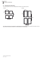
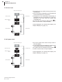
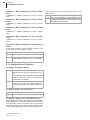
Step 1: Electrical connection
Step 1: Electrical connection
Ú Connect the thermocouple between terminal 10 and
11.
Ú A Solid State Relay (SSR) is used as a power control-ler. Notice the heat output at switching to select
the correct SSR.
To activate the Solid State Relay connect it to ter-minal 5(+) and 6(-) of the controller.
Ú Connect the heater with power supply and Solid
State Relay. Use ultra rapid micro-fuse or ultra ra-pid
automatic circuit breaker for fuse protection of the
heating circuit.
Ú Connect the power supply of the controller by ter-minal 1 and 2 (e.g. 230 VAC).
Notice necessarily the specification of the
power supply of the controller (85...250
VAC or 24 V)!
Provide fuse protection.
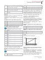
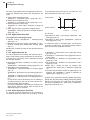
Ú Connect the thermocouple between terminal 10 and
11.
Ú A Solid State Relay (SSR) is used as a power control-ler. Notice the heat output at switching to select the
correct SSR.
To activate the Solid State Relay connect it to termi-nal 17(+) and 24(-) of the controller.
For the power supply of the control output
there must be an additional connection bet-ween terminal 1 and 16.
Ú Connect the heater with power supply and Solid State
Relay. Use ultra rapid micro-fuse or ultra rapid auto-matic circuit breaker for fuse protection of the heating
circuit.
Ú Connect the power supply of the controller by terminal
13 and 14 (e.g. 230 VAC)
Notice necessarily the specification of the
power supply of the controller (85...250 VAC
or 24 V)!
Provide fuse protection.
L
N
Delay-action Fuse
Fuse,
ultra-rapid
1
Heating
Unit
13
14
8
3
9
5
6
15
L
25
10
1
13
11
2
14
16
12
3
15
Temperature
Sensor
4
5
Temperature
Sensor
DOUT
1
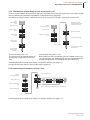
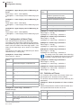
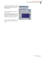
Step 2: Adjust sensor type *)
Fuse,
ultra-rapid
16
SSR
17
6
18
7
19
8
20
9
21
10
22
11
23
12
24
27
N
Delay-action
Fuse
26
DOUT
1
4
SSR
7
2
Heating
Unit
28
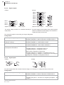
Step 2: Adjust sensor type *)
f
f
Ú Press button
repeatedly until SEn is shown in
the display.
or
.
Ú Choose sensor type with the buttons
Ú Confirm sensor type with
and return to actual/set
point value display with
.
Ú Press button
repeatedly until SEn is shown in the
display.
or
.
Ú Choose sensor type with the buttons
Ú Confirm sensor type with
and return to actual/set
point value display with
.
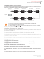
Step 3: Adjust set point *)
Step 3: Adjust set point *)
f
a
s d
a
Ú Press button
repeatedly until SP is shown in the
display.
and change set point with
and
.
Ú Press
Ú Confirm set point entry with button
and return
with
or
to actual/set point value display.
f
s d
s
f
d
f
a
s d
a
Ú Press button
repeatedly until SP is shown in the
display.
and change set point with
and
.
Ú Press
Ú Confirm set point entry with button
and return with
or
to actual/set point value display.
f
s d
s
f
d
Technical changes reserved
Rev. 1.01.07
2
1 Introduction
4
2 Warranty Conditions
4
3 Installation and safety references
4
4 Installation and Start-up
6
Scope of supply
Equipment implementation/Ordering designations
Type plate
Type designation
Mounting and Housing
Exchange of Controller
Electrical Connection and Base Configuration
Connection overview
Standard Equipment
Power supply
Sensor-/measurement inputs
Digital outputs
Digital inputs
Heating Current Monitoring
Options
Serial Interface RS485 (2-wire) (Option A)
Serial Interface RS485 (4-wire) (Option A and B)
CAN-Bus (Option B)
Analog Outputs (Option A and B)
Digital in-/outputs (Option A and B)
5 Display and Operation
Front view
Display Loc
Display of Examples of Operation
Display of Buttons
Display of LED
Steps of Operation in Flow-Chart
Operation Levels
Direct data entry of set point and degree of operation
Information Level
User Level
System Level
Two Methods of Data Entry at User and System Level
Unblocking of Parameters at User Level
Additional Operating Functions
Enter Code Number
Software Version / Period of Operation
Activate Input block on User -/System Level
Messages & Displays
Status Messages
6 Configuration / Setting
Main functions
Control parameter
Group functions
Definition of Temperature Limit Values
Configuration of Base functions
Rev. 1.01.07
Technical changes reserved
6
6
6
7
8
10
10
10
11
11
11
12
12
13
13
13
14
14
14
15
17
17
17
18
18
18
18
19
20
20
22
22
23
23
24
24
25
25
26
26
28
28
30
31
31
32
PSG Plastic Service GmbH
Operating Instructions ETR45&ETR46
Display
Configuration of Hardware
Configuration of Alarm Flags
Definition of Timers
Configuration of Operation
Configuration of Data Interface
Basic settings for Special Applications
Application Hot Runner Control
Application Extrusion
Application Hot Air
Alarm Hysteresis Function
7 Appendix
Parameters/factory delivery status
Firmware update
Version History
33
33
36
36
38
39
39
39
40
40
40
41
41
44
47
Rev. 1.01.07
Technical changes reserved
3
4
Chapter 1
Introduction
1
Introduction
The compact controller models ETR45 and ETR46 are one zone temperature controllers (dimensions 48x48mm
and 48x96mm) with adaptive parameter adjustment. They are applicable for all purpose applications in extremely
fast to extremely slow zones.
The controllers are available in different specifications. This has to be considered at installation and start-up. For
details please refer to chapter ÓEquipment implementation/Ordering designations as well as ÓConfiguration / Setting.
These operating instructions assist in case of first installation and start-up of the controller as well as in case of
changes and adjustment of an existing control system. Status and error messages are described and remedies
are recommended for elimination of faults.
Protocol specifications of the serial interface and CAN-Bus are not integral part of the operating instructions. The
specifications are available on request.
Symbols and explanation
Caution
In case of non-compliance with or inaccurate compliance there can result damage to the
device or injuries to persons.
Note
Attention is drawn to a special feature.
Example
Function is explained by an example.
After June 2014 the design of the Info button / Escape button was changed (before June 2014 an „i“
was shown in a circle).
2
Warranty Conditions
This product is subject to the legal warranty time periods for faults or deficiencies in manufacture.
Content of Warranty
If there is a malfunction due to production, PSG Plastic Service GmbH rectifies the fault or replaces the defective
product at their own discretion.
The following repairs do not fall under the warranty and are liable to costs:
Ú Malfunctions after the legal notice periods have expired.
Ú Malfunctions caused through operating error of the user (if the device is not operated as described in the manual).
Ú Malfunctions caused through other devices.
Ú Changes or damage to the device which do not originate from the manufacturer.
For services due to these terms of guarantee please contact PSG Plastic Service GmbH.
3
Installation and safety references
Before installation, handling or operation of the device, please read through this operating instructions
completely and carefully.
This controller fulfils the European Directives of security and EMC. It is the responsibility of the operator
to observe the directives at installation of the device.
Technical changes reserved
Rev. 1.01.07
PSG Plastic Service GmbH
Operating instructions ETR45&ETR46
CE marking
The device complies with the European Directives for electromagnetic compatibility (complies with EN 61326-1)
and low voltages (complies with EN 61010-1).
Service and repair
This device is maintenance free.
In case of error, please contact PSG Plastic Service GmbH. Repair by customer is prohibited.
Cleaning
Employ no water or cleaning agents based on water for the cleaning of the device stick-on labels. You can clean
the surface of the devices with a mild soap solution.
Storage
If you should not put the device into operation immediately after unpacking, protect it against moisture and coarse
dirt.
Personnel
The installation of the device may by carried out by qualified personnel only.
Wiring
The wiring system must be implemented correctly according to the specifications in this operating manual. All
feeds and connecting terminals must be dimensioned for the corresponding amperage. Furthermore, all connections are to be carried out according to the valid VDE Specification and/or the respective national specifications.
Ensure in particular that the AC power supply is not connected with the logic output or the low-voltage input.
Overload protection
For the power supply of the controller and the controller outputs use a fuse protection or a circuit breaker. That
protects the printed circuit board against overload.
Maximum Voltage for Devices with Power Supply of 85...250VAC
For controllers with a power supply of 85...250VAC the maximum applied voltage on the terminals has to be less
than 250 VAC.
DO NOT connect the controller to three phase systems or grounded midpoints. In case of an error the voltage of
the power supply can exceed 250 VAC. Under these circumstances the device is not reliable.
Voltage transients on power supply terminals and between power supply and ground should not exceed 2.5 kV.
For transients expect to exceed 2.5 kV, the power supply voltage should be limited to 2.5 kV by an over voltage
protection.
Environment
Conducting contamination must not reach the proximity of the device connecting terminals in the control cabinet.
In order to achieve suitable ambient air conditions, install an air filter in the air inlet of the control cabinet. If the
controller should be in a condensing environment (low temperatures), install a thermostat-controlled heating unit
in the control cabinet.
Technical changes reserved
Rev. 1.01.07
5
6
Chapter 4
Installation and Start-up
4
Installation and Start-up
4.1 Scope of supply
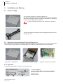
The controller is packed in a robust cardboard box.
Check the packaging and then the temperature controller for identifiable
damage incurred during transit. If damage is identified, then please get
in touch with the transportation company.
In case of damage DO NOT put the controller into operation.
Two securing brackets (see figure) and the operating instructions are included in the box.
4.2 Equipment implementation/Ordering designations
When ordering the controller it is important to specify what options are required (refer to ). The exact specification
can be read on the type plate on the cardboard box, the controller housing and the printed circuit board.
Type plate on cardboard box
Type plate on controller housing
Type plate on printed circuit board
4.2.1 Type plate
The following information can be taken from the type plate:
1
2
3
4
5
Technical changes reserved
Rev. 1.01.07
ÓType designation
Revision identification of the printed circuit boards
Revision identification of the controller software
Order number
Serial number
PSG Plastic Service GmbH
Operating instructions ETR45&ETR46
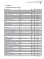
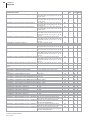
4.2.2 Type designation
The type designation specifies the controller model and consists of the following options.
Controller Type
ETR45
ETR46
Input A
TCPT
Thermocouple/Pt100
TCPT
Thermocouple/Pt100
Input B
-
-
U
0/2...10VDC
Input C
-
-
I
0/4...20mA
Digital output 1
TS
Optical coupler
TS
Optical coupler
Digital output 2
TS
R
Optical coupler
Relay
TS
R
Optical coupler
Relay
Digital output 3
-
-
TS
R
Optical coupler
Relay
Digital output 4
-
-
TS
R
Optical coupler
Relay
Option A
RS 485
U
I
DIO
RS485 T
Not existing
Serial interface (2-wire)
Analog output 0/2...10VDC
Analog output 0/4...20mA
Digital inputs/outputs
Serial interface (4-wire)*
RS 485
U
I
DIO
RS485 T
Not existing
Serial interface (2-wire)
Analog output 0/2...10VDC
Analog output 0/4...20mA
Digital inputs/outputs
Serial interface (4-wire)*
Option B
CAN
U
I
DIO
RS 485 R
Not existing
CAN interface
Analog output 0/2...10VDC
Analog output 0/4...20mA
Digital inputs/outputs
Serial interface (4-wire)*
CAN
U
I
DIO
RS 485 R
Not existing
CAN interface
Analog output 0/2...10VDC
Analog output 0/4...20mA
Digital inputs/outputs
Serial interface (4-wire)*
Voltage
230 VAC
24 V
85...250 VAC
24 VAC/DC
230 VAC
24 V
85...250 VAC
24 VAC/DC
* RS485 4-wire only possible for option A = RS485T and option B = RS485R.
Technical changes reserved
Rev. 1.01.07
7
Chapter 4
Installation and Start-up
4.3 Mounting and Housing
The control panel cut out has to be prepared according to the following sketch:
ETR45
ETR46
45 mm
+0,5/-0,0
83mm
92mm
+0,5/ -0,0
45 mm
+0,5/-0,0
45 mm
+0,5/-0,0
8
130mm
55mm
55mm
When fitting more than one controller in a control panel the correct spacing of the controllers is necessary. A spa-cing of 10mm in horizontal, and 38mm in vertical direction is recommended.
Technical changes reserved
Rev. 1.01.07
PSG Plastic Service GmbH
Operating instructions ETR45&ETR46
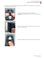
The controllers ETR45 and ETR46 are equipped with a straightforward mounting system. The housing can be
mounted / removed without any tools.
To mount the controller, remove the securing brackets.
Press the securing brackets at the end (1), move it backward (2) out of
the guides.
Pass the controller into the front side of the control panel cut out or re-move it from the front side.
Refit the securing brackets into the guides again and push it forward.
Technical changes reserved
Rev. 1.01.07
9
Chapter 4
Installation and Start-up
4.4 Exchange of Controller
For an exchange of a controller the housing need not to be removed.
Press the lock at the lower end of the front side and remove the controller from
the housing (see figure).
Only controllers of the same type should be exchanged. Notice to take over the setting of the controller.
4.5 Electrical Connection and Base Configuration
The controller may be installed and put into operation by specialist personnel only.
Before switch-on of the control zones it is to be ensured that the controller is configured for the application. An incorrect configuration can lead to damage to the control section or to injuries to persons.
The wiring system is implemented on the screwed terminals on the rear side with the appropriate cable lugs. Cables with a cross section of 0.5 to 1.5mm2 can be employed.
The start-up of the controller includes the electrical installation as well as the correct configuration. Succeeding
the terminal allocation and instructions on the configuration are given in detail.
4.5.1 Connection overview
The terminal overview is glued on one side of the controller next to the type plate. All feasible connections are
drawn in. Only controller configured variants can be used.
ETR46
DIN1+/DOUT1RS485 TXAOUT1RS485 TX- (4-wire)
L 1
13
DIN1-/DOUT1+
RS485 TX+
AOUT1+
RS485 TX+ (4-wire)
14
N 2
DOUT
2
DOUT
1
3
supply With power supply 24 V:
R TS
7
+12VDC
8
DIN
9
4
10
5
11
0V 6
15
16
12 GND
DIN2-/DOUT2+
CAN-H
AOUT2+
RS485 RX+ (4-wire)
+/~
24V
-/~
I
DOUT
2
DOUT
1
1
13
DIN1-/DOUT1+
RS485 TX+
AOUT1+
RS485 TX+ (4-wire)
14
2
3
R TS
7
+12VDC
8
DIN
9
STI
4
10
5
11
0V 6
15
DIN2+/DOUT2CAN-L
AOUT2RS485 RX- (4-wire)
16
DIN1-/DOUT1+
RS485 TX+
AOUT1+
RS485 TX+ (4-wire)
25
I
DIN1+/DOUT1RS485 TXAOUT1RS485 TX- (4-wire)
25
DIN1 2
DIN1+/DOUT1RS485 TXAOUT1RS485 TX- (4-wire)
26
1
13
+/~
14 N
DIN1 2
14
-/~
DIN2 3
15
DIN2 3
15
4
16
4
16
5
17
5
17
6
18
6
18
7
R 19
0V
I
B
STI
I0V
C
TS
8
20
9
TS R
21
TS R
23
10
A
22
11
12
DIN2-/DOUT2+
CAN-H
AOUT2+
RS485 RX+ (4-wire)
+12VDC
0V
DOUT
1
DOUT
2
DOUT
3
DOUT
4
24 0V
27
Technical changes reserved
Rev. 1.01.07
DIN1-/DOUT1+
RS485 TX+
AOUT1+
RS485 TX+ (4-wire)
26
13 L
12 GND
DIN2-/DOUT2+
CAN-H
AOUT2+
RS485 RX+ (4-wire)
supply With power supply 24 V:
1
+12VDC
0/2...10 V
DIN2+/DOUT2CAN-L
AOUT2RS485 RX- (4-wire)
STI
DIN1+/DOUT1RS485 TXAOUT1RS485 TX- (4-wire)
With
power
85...250 VAC:
28
DIN2+/DOUT2CAN-L
AOUT2RS485 RX- (4-wire)
I
B
0/2...10 V
With
power
85...250 VAC:
A
STI
I0V
C
0/4...20mA
ETR45
0/4...20mA
10
7
TS R
19
20
8
9
TS R
21
10
22
11
TS R
23
12
24V
DOUT
1
DOUT
2
DOUT
3
DOUT
4
24 0V
27
DIN2-/DOUT2+
CAN-H
AOUT2+
RS485 RX+ (4-wire)
28
DIN2+/DOUT2CAN-L
AOUT2RS485 RX- (4-wire)
PSG Plastic Service GmbH
Operating instructions ETR45&ETR46
4.5.2 Standard Equipment
4.5.2.1
Power supply
Controller Type
ETR45
ETR45
ETR46
ETR46
Power supply
230 VAC
24V
230 VAC
24V
Range
85...250 VAC
18...24 VAC or
18...36 VDC
85...250 VAC
18...24 VAC or
18...36 VDC
+/~
1
13
+/~
-/~
2
14
-/~
Power consumption
6.5W
6.5W
6.5W
6.5W
Fuse
200mA time lag
800mA time lag
200mA time lag
800mA time lag
Fuse protection of the controller always externally.
4.5.2.2
Sensor-/measurement inputs
Compared to ETR45 with one measuring input, ETR46 has three measuring inputs. It can be selected
which of these three measuring inputs or which combination of these is used as actual value.
Furthermore the presetting of the set point for ETR46 can be done by measuring input additional to entry
by keypad or data interface.
0/4...20mA
Thermocouple
0/2...10VDC
12
Pt100 2-wire
GND
11
Pt100 3-wire
AIN A -
Pt100 2-wire
AIN A+ 10
Pt100 3-wire
ETR46
Thermocouple
ETR45
7
AIN B
8
AIN C
9
10
AIN A+
11
AIN A-
12
GND
Configuration
Define measuring input A
Ú Page35: [P072]SEn - Sensor Type of Measuring Input A
Ú Page35: [P075]oFF.A - Offset of Measuring Input A
Define measuring input B and C
(only ETR46)
Ú Page35: [P078]Aib.L - Lower Display Limit of Measuring Input B
Ú Page36: [P079]Aib.H - Upper Display Limit of Measuring Input B
Ú Page36: [P080]AiC.L - Lower Display Limit of Measuring Input C
Ú Page36: [P081]AiC.H - Upper Display Limit of Measuring Input C
Define function for measuring inputs
(only ETR46)
Ú Page35: [P073]SEn.C - Measuring Input for Control
Define input range for set point
Ú Page35: [P074]Sen.S - Measuring Input for Presetting of Set
Point
Ú Page32: [P051]SP.Lo - Lower Set Point Limit
Ú Page32: [P052]SP.Hi - Upper Set Point Limit
Technical changes reserved
Rev. 1.01.07
11
12
Chapter 4
Installation and Start-up
4.5.2.3
Digital outputs
ETR45
ETR46
/+Uext
DOUT1+ 16
1
DOUT1-
24 /0Vext
17
/+Uext
DOUT2+ 18
1
DOUT2-
24 /0Vext
19
DOUT3+ 20
DOUT3-
21
1
6
/0Vext
DOUT2
3
7
/+Uext
3
DOUT4+ 22
1
DOUT2-
4
6
/0Vext
4
DOUT4-
24 /0Vext
Optical coupler outputs
Relay outputs
Optical coupler outputs
20
21
24 /0Vext
5
23
19
/+Uext
DOUT1
18
/+Uext
22
23
Relay outputs
The power supply of DOUT1 is controller internally al-- As power supply for the outputs of the optical couplers
ready wired.
either the controller internal voltage or an external d.c.
voltage (24 VDC) can be used.
The controller outputs are according to the type designation.
Configuration
Which output on digital outputs?
Ú Page33: [P058]dO.1 - Mode of Operation of Digital Output 1 to
Ú Page34: [P061]dO.4 - Mode of Operation of Digital Output 4
Is a relay connected to the control output Ú Page32: [P049]rEL.H - Relay Output Heating
heating or cooling?
Ú Page32: [P050]rEL.C - Relay Output Cooling
Is control output used for output of alarm?
Ú Page36: [P082]A1.d1 - Alarm Flag 1, Definition 1 to
Page36: [P089]A4.d2 - Alarm Flag 4, Definition 2
Additional setting if output is used for output Define alarm limits
of temperature limit alarms
Ú Page28: [P007]Li.1 - Temperature Limit 1 to
Page28: [P010]Li.4 - Temperature Limit 4
Define mode of operation of alarm limits
Ú Page32: [P041]Li.1d - Definition of Temperature Limit 1 to
Page32: [P044]Li.4d - Definition of Temperature Limit 4Page32:
[P044]Li.4d - Definition of Temperature Limit 4
4.5.2.4
Digital inputs
ETR45
ETR46
As power supply either the controller internal voltage or an external d.c. voltage (24 VDC) can be used.
Configuration
Define mode of operation of digital inputs.
Ú Page34: [P062]dIn.1 - Mode of Operation of Digital Input 1
Ú Page34: [P063]dIn.2 - Mode of Operation of Digital Input 2
Is digital input used to activate a set point? Define set point
Ú Page28: [P011]SP.2 - Set Point 2 to Page29: [P013]SP.4 - Set
Point 4
Technical changes reserved
Rev. 1.01.07
PSG Plastic Service GmbH
Operating instructions ETR45&ETR46
Setting if digital input is used to start a timer Define duration of timer
Ú Page29: [P017]t1 - Process Timer 1 to
Page29: [P020]t4 - Process Timer 4
Define mode of operation of timer
Ú Page37: [P090]t1.d1 - Mode of Operation of Timer 1, Definition 1
to
Page38: [P097]t4.d2 - Mode of Operation of Timer 4, Definition 2
Define mode of operation of timer in case of disturbance
Ú Page38: [P098]t.rES - Mode of Operation of Timer after Soft-Reset
4.5.2.5
Heating Current Monitoring
ETR45
ETR46
Do only use current transformers available in the accessories by PSG Plastic Service GmbH.
Configuration
Define measuring method.
Ú Page32: [P053]Cur.d - Current Supervision Function
Define upper limit of measurement range.
Ú Page33: [P054]Cur.E - Final Value of Measurement Range of
Current Supervision
Define heating current and tolerance
Ú Set point of current either
directly entered: Page28: [P004]Cur.S - Set Point of Heater Current or
by automatic current transfer Page20: Information Level
Ú Page28: [P005]Cur.t - Tolerance Band of Heater Current
4.5.3 Options
In addition to the standard equipment the controller can be equipped with two options (Option A and B).
4.5.3.1
Serial Interface RS485 (2-wire) (Option A)
ETR45
ETR46
TX
TX
25 26
The RS485 connection admits to communicate with 32 controllers by PC over a great distance. A shielded wire
has to be used.
Configuration
Define option
Ú Page34: [P064]OPt.A - Definition of Option A define as rS
Define communication protocol
Ú Page39: [P102]S.Pro - Protocol of Serial Interface
Define setting of interface
Ú Page39: [P101]S.Adr - Address of serial interface
Ú Page39: [P103]S.bd - Baud Rate of Serial Interface
Ú Page39: [P104]S.Sto - Stop Bits of Serial Interface
Ú Page39: [P105]S.PAr - Parity of Serial Interface
Additional setting if communication protocol Ú Page39: [P109]m.Adr - MODBUS address
is in mode MODBUS
Technical changes reserved
Rev. 1.01.07
13
14
Chapter 4
Installation and Start-up
4.5.3.2
Serial Interface RS485 (4-wire) (Option A and B)
ETR45
ETR46
Option A
Option B
Option A
TX
15 16
RX
Option B
TX
27 28
25 26
RX
RX
RX
RS485 4-wire only possible for option A = RS485T and option B = RS485R.
Configuration
Ú Page34: [P064]OPt.A - Definition of Option A define as rS
Define option
Ú Page34: [P065]OPt.b - Definition of Option B define as rS
Define communication protocol
Ú Page39: [P102]S.Pro - Protocol of Serial Interface
Define setting of interface
Ú Page39: [P101]S.Adr - Address of serial interface
Ú Page39: [P103]S.bd - Baud Rate of Serial Interface
Ú Page39: [P104]S.Sto - Stop Bits of Serial Interface
Ú Page39: [P105]S.PAr - Parity of Serial Interface
Additional setting if communication protocol Ú Page39: [P109]m.Adr - MODBUS address
is in mode MODBUS
4.5.3.3
CAN-Bus (Option B)
ETR45
ETR46
27 28
15 16
CAN-L
CAN-H
CAN-H
CAN-L
Up to 127 controllers can be connected by CAN-Bus. Beside the communication with a superior control/visualiza-tion system the remote control function is feasible. For more detailed information please refer to ÓConfiguration
of Data Interface.
Configuration
Define option
Ú Page34: [P065]OPt.b - Definition of Option B define as CAn
Define setting of interface
Ú Page39: [P106]C.bAS - CAN base address
Ú Page39: [P107]C.bd - CAN baud rate
Ú Page39: [P108]C.OP - CAN Auto Operational Mode
4.5.3.4
Analog Outputs (Option A and B)
ETR45
ETR46
27 28
15 16
13 14
25 26
Both options of the controller can be of the analog output type.
Configuration
Define option
Technical changes reserved
Rev. 1.01.07
Ú Page34: [P064]OPt.A - Definition of Option A and
Page34: [P065]OPt.b - Definition of Option B
define as AO or AO.O
PSG Plastic Service GmbH
Operating instructions ETR45&ETR46
Stipulate function of the analog outputs.
4.5.3.5
Ú Page35: [P070]AO.A - Mode of Operation of Analog Output Option A and
Page35: [P071]AO.b - Mode of Operation of Analog Output Option B
Digital in-/outputs (Option A and B)
ETR45
ETR46
Digital outputs
Digital outputs
0Vext
or
6 /0Vint
+Uext
or
7 /+Uint
0Vext
or
4 /0Vint
13/15 14/16
Digital inputs
26/28 25/27
Digital inputs
0Vext
or
6 /0Vint
+Uext
or
7 /+Uint
+Uext
or
1 /+Uint
0Vext
or
4 /0Vint
+Uext
or
1 /+Uint
13/15 14/16
26/28 25/27
Configuration
Define option
Ú Page34: [P064]OPt.A - Definition of Option A and
Page34: [P065]OPt.b - Definition of Option B
define as dI or dO
Option digital output dO is defined:
Define mode of operation of digital output.
Ú Page34: [P066]dO.A - Mode of Operation of Digital Output Option
A and
Page34: [P067]dO.b - Mode of Operation of Digital Output Option
B
Is control output used for output of heating Ú Page32: [P049]rEL.H - Relay Output Heating
or cooling?
Ú Page32: [P050]rEL.C - Relay Output Cooling
Is control output used for output of alarm?
Ú Page36: [P082]A1.d1 - Alarm Flag 1, Definition 1 to
Page36: [P089]A4.d2 - Alarm Flag 4, Definition 2
Additional setting if output is used for output Define alarm limits
of temperature limit alarms
Ú Page28: [P007]Li.1 - Temperature Limit 1 to
Page28: [P010]Li.4 - Temperature Limit 4
Define mode of operation of alarm limits
Ú Page32: [P041]Li.1d - Definition of Temperature Limit 1 to
Page32: [P044]Li.4d - Definition of Temperature Limit 4Page32:
[P044]Li.4d - Definition of Temperature Limit 4
Option digital input dI is defined:
Define mode of operation of digital input
Ú Page34: [P068]dIn.A - Mode of Operation of Digital Input Option
A and
Page34: [P069]dIn.b - Mode of Operation of Digital Input Option B
Is digital input used to activate a set point? Define set point
Ú Page28: [P011]SP.2 - Set Point 2 to Page29: [P013]SP.4 - Set
Point 4
Technical changes reserved
Rev. 1.01.07
15
16
Chapter 4
Installation and Start-up
Setting if digital input is used to start a timer Define duration of timer
Ú Page29: [P017]t1 - Process Timer 1 to
Page29: [P020]t4 - Process Timer 4
Define mode of operation of timer
Ú Page37: [P090]t1.d1 - Mode of Operation of Timer 1, Definition 1
to
Page38: [P097]t4.d2 - Mode of Operation of Timer 4, Definition 2
Define mode of operation of timer in case of disturbance
Ú Page38: [P098]t.rES - Mode of Operation of Timer after Soft-Reset
Technical changes reserved
Rev. 1.01.07
PSG Plastic Service GmbH
Operating instructions ETR45&ETR46
5
Display and Operation
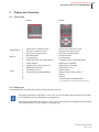
5.1 Front view
ETR45
A
ETR46
B
C
D
E
A B
C
1
1
2
2
D
3
4
5
E
F
G
H
6
3
5
6
4
LED displays
1
2
Actual value / Parameter value
Set point / Parameter name
Actual value / Parameter value
Set point / Parameter name
Buttons
3
4
5
6
Info button / Escape button
Decrease button
Increase button
Parameter button / Edit Enter button
Info button / Escape button
Decrease button
Increase button
Parameter button / Edit Enter button
LEDs
A
B
C
D
E
F
G
H
Output heating
Output cooling / alarm output 3 *)
Digital input activated
Temperature unit °F
Communication RS485/CAN-Bus
-
Digital input 1 activated
Digital output 2 activated
Temperature unit °F
Output heating
Output cooling / alarm output 3 *)
Alarm 1
Alarm 2
Communication RS485/CAN-Bus
*) see Ó[P087]A3.d2 - Alarm Flag 3, Definition 2 (page 36)
5.1.1 Display Loc
Is Loc displayed in the actual value display; an input blocking is active.
See setting of parameter Ó[P100]iLoc - Entry Lock on Info Level (page 38) and chapter ÓTwo Methods of Data Entry at User and System Level (page 23).
See setting of parameter Ó[P110]ULoc - Entry Lock on User/System level (page 38) and chapter
ÓActivate Input block on User -/System Level (page 25).
Technical changes reserved
Rev. 1.01.07
17
18
Chapter 5
Display and Operation
5.2 Display of Examples of Operation
Display of Buttons
To illustrate the operation the symbols have the following meaning:
a
a
df
df
Press button
Keep the button pressed
d pressed and press button f additionally
Shortcut: First keep button d pressed, then keep button f additionally pressed
Shortcut: Keep button
Press button
s or button d.
Display of LED
The display of actual value / set point is in gray color for a better identification. All other
LED displays have a black background.
200
200
200
SP.
off
manU
Display, when set point or one parameter value is flashing.
Steps of Operation in Flow-Chart
All steps of operation are explained by flow-charts. In the flow-charts the display as well as the buttons are shown
in combination.
Please follow the arrows in the flow-chart to comprehend the steps of operation.
Technical changes reserved
Rev. 1.01.07
PSG Plastic Service GmbH
Operating instructions ETR45&ETR46
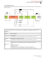
5.3 Operation Levels
Beside the direct data entry the operation and configuration of the controller takes place in 3 sublevels starting
from the main level:
a
Direct entry
Setpoint/
Degree of operation*
a
Actual-/setpoint value (control mode)
Main level
Actual value/degree of operation (manual
mode)
Information
Level
User Level
USEr
System Level
SYS
Enabling
User level
a
a
a
* Direct data en- Direct data entry of set point (the controller is in control mode) and degree of operation (the
try of set point controller is in manual mode) only for Ó[P099]Edit - Entry Mode Directly (page 38) = on.
and degree of
operation
Main level
In the main level actual value and set point and actual value and degree of operation respectively are displayed.
Display and operation of the often used process parameters (set point, manual mode, heating
Information Level current, alarm).
Is Loc displayed in the actual value display; see chapter ÓDisplay Loc (page 17).
User Level
USEr
Display and operation of parameters that are occasionally displayed and changed. The list of
parameters can be arranged individually.
Is Loc displayed in the actual value display; see chapter ÓDisplay Loc (page 17).
Display and operation of all parameters.
Unblocking at user level: Additionally to the parameter value each parameter has an unblock
information at user level. This defines the status of the parameter at user level:
System Level
SYS
Ú hidden
Ú visible/not changeable or
Ú visible/changeable.
The display at user level can individually be arranged for the application.
Is Loc displayed in the actual value display; see chapter ÓDisplay Loc (page 17).
Technical changes reserved
Rev. 1.01.07
19
20
Chapter 5
Display and Operation
5.3.1 Direct data entry of set point and degree of operation
In the direct data entry mode the set point and the degree of operation are directly changed by pressing the buttons
or
.
s d
Ú At direct data entry the data entry is accepted three seconds after the last entry.
.
Ú The data entry is accepted immediately after pressing the button
Ú Pressing the button
within the three seconds the data entry is canceled.
a
f
The program returns to main level and displays actual value/set point and actual value/degree of operation re-spectively.
Is Loc displayed in the actual value display; see chapter ÓDisplay Loc (page 17).
5.3.2 Information Level
In the information level set point, manual mode, heating current and alarms are directly accessible by button
At information level
Ú set points for temperature can be changed,
Ú manual mode can be switch on/off and degree of operation can be adjusted,
Ú an automatic current transfer can be made as well as
Ú display of alarms and acknowledgement
.
Is Loc displayed in the actual value display; see chapter ÓDisplay Loc (page 17).
Technical changes reserved
Rev. 1.01.07
a.
PSG Plastic Service GmbH
Operating instructions ETR45&ETR46
Select setpoint value
a
>
<
200
SP
Select
Degree of Operation
200
SP.
Enable entry of
setpoint
250
SP.
Change
setpoint
value
Confirm change
a
>
<
20
Out.
Select
Heating current
a
off
manU
Select manual
mode
off
manU
Deactivate manual mode
on
manU
200
200
Activating manual mode
Display actual value/set
point
5.8
Cur.
Select alarm
display
a
on
CSET
Enable current
transfer
No current transfer
Execute current
transfer
a
C L
Al.
on
AL
Select acknowledgement of
alarms
Enable entry of degree
of operation
25
Out
Change degree of operation
Confirm
change
off
CSET
on
CSET
>
<
20
Out
Display current setpoint
value
5.8
Cur.S
Change current setpoint
value
5.9
Cur.S
Activate current transfer
off
AL
No acknowledge of alarms
on
AL
Acknowledge
alarms
Ú If there is no operating function chosen awaiting a data entry (i.e. the upper LED display is flashing), the infor-mation level can directly be left by button
or
.
Ú Is Loc displayed in the actual value display; see chapter ÓDisplay Loc (page 17).
d s
Technical changes reserved
Rev. 1.01.07
21
22
Chapter 5
Display and Operation
5.3.3 User Level
Ú By call of user level USEr is shortly shown in the
LED dis-play.
Display actual value/set point
Ú In the user level it is feasible to scroll forward and
back-ward between the parameters.
200
200
a
Select user level
Exit user level
User
Display for about 1
second
Ú It depends on the unblocking (ÓUnblocking of
Parameters at User Level (page 23)), which parameters at the user level are vi-sible and
changeable too.
The user level can always be left by button
to
return to actual value / set point display.
a
200
SP
Is Loc displayed in the actual value display; see
chapter ÓDisplay Loc (page 17).
Scroll backwards
Scroll forwards
Auto
C.Op
5.3.4 System Level
Ú By call of system level SYS is shortly shown in
the LED display.
Display actual value/set point
200
200
a
Select system level
Display for about 1
second
Exit system level
SYS
Scroll forwards
Auto
C.OP
Technical changes reserved
Rev. 1.01.07
a
Is Loc displayed in the actual value display; see
chapter ÓDisplay Loc (page 17).
200
SP
Scroll backwards
Ú In the system level it is feasible to scroll forward
and backward between the parameters
The system level can always be left by button
to return to actual value / set point display.
PSG Plastic Service GmbH
Operating instructions ETR45&ETR46
5.3.5 Two Methods of Data Entry at User and System Level
It can be chosen between two methods of data entry for parameters at user and system level. The method of data
entry is defined by the parameter Ó[P099]Edit - Entry Mode Directly (page 38).
The difference between the two methods is shown by the example of a change of a set point at user level.
Display
Actual value/set
point
200
200
Select user level
Display for about 1
second
Setpoint value
flashes
Display
Actual value/set point
User
Deactivate input block:
Press buttons consecutively
in between 0.5 seconds
200
200
Select user level
Display for about 1 second
200
SP
200
SP
User
Change of setpoint value
200
SP
Change setpoint
value directly
Setpoint value flashes
250
SP
250
SP
Confirm change and call the
next parameter
Confirm change
and call the next
parameter
Direct Data Entry (Edit = on)
The set point can be entered directly after selec-tion. Unblocking is not necessary.
Unblock Data Entry (Edit = oFF)
Before data entry the input blocking must be enabled at user level.
The input blocking is an additional step to prevent unintentional parameter changes which are feasible by the direct data entry.
Is Loc displayed in the actual value display; see chapter ÓDisplay Loc (page 17).
For input blocking also refer to ÓEnter Code Number (page 24).
5.3.6 Unblocking of Parameters at User Level
Display
Actual value/set point
200
200
edit
SP
Select system level
Display for about 1 second
a
Select unblocking level
hide
SP
loc
SP
sys
Confirm unblocking and call unblocking for the next parameter
Setpoint value flashes
200
SP
Is Loc displayed in the actual value display; see chapter ÓDisplay Loc (page 17).
Technical changes reserved
Rev. 1.01.07
23
24
Chapter 5
Display and Operation
For each parameter the unblocking defines whether the parameter is visible and changeable at user level. The
display at user level can individually be arranged for the application.
Parameter visible
Parameter changeable
Edit
yes
yes
hidE
no
no
Loc
yes
no
a
To return from unblocking to system level use button
.
For factory-made settings concerning unblocking please refer to ÓAppendix (page 41).
5.4 Additional Operating Functions
5.4.1 Enter Code Number
Code numbers are used to call complex functions or system functions.
Display actual value/set point
Select entry of code
number
200
200
0
Code
Change code number
111
Code
Activate function by
code number
The following code numbers exist for this controller:
Code number Function
1...100
Input blocking (see parameter Ó[P110]ULoc - Entry Lock on User/System level (page 38)) is temporary released (1 minute after the last key operation activated again).
111
Start automatic identification cooling
Prerequisite to start the function is that the zone is in a adjusted status.
211
Deactivate input block (see parameter Ó[P099]Edit - Entry Mode Directly (page 38))
212
Activate input block (see parameter Ó[P099]Edit - Entry Mode Directly (page 38))
All data entry, except set point data entry, is locked. The input blocking is fail-safe. By entry of
code number 211 the data entry blocking is deactivated.
445
Stop identification heating
The function that calculates the control parameters during heating is directly stopped.
999
Perform controller reset
After activation of the code number the controller makes a new start.
Technical changes reserved
Rev. 1.01.07
PSG Plastic Service GmbH
Operating instructions ETR45&ETR46
5.4.2 Software Version / Period of Operation
The display of software version and period of operation are only for reasons of maintenance. Please keep this data
ready in case of queries for the controller at PSG Plastic Service GmbH.
Press button for at
least 12 seconds
Display
Actual value/
set point
Software identifier #1
Software identifier #2
Monitor version #1
Monitor version #2
a
4601
InF1
a
0705
Inf2
a
4500
Inf3
a
a
22
Ot.h
a
10
Ot.d
a
0
Ot.y
a
0004
InF4
200
200
Period of operation - hours
Period of operation - days
Period of operation - years
The firmware of the controller is of calendar week 07/2005 (software identification #2).
The period of operation is 10 days and 22 hours.
For software identifier #1 and the two monitor identifiers additional system information is available.
Exit dialog level by pressing button
s or button d.
5.4.3 Activate Input block on User -/System Level
The input on user level USEr and on system level SYS can be blocked by parameter Ó[P110]ULoc - Entry Lock
on User/System level (page 38).
This setting overrides the setting of parameter Ó[P099]Edit - Entry Mode Directly (page 38).
For setting of parameter Ó[P110]ULoc - Entry Lock on User/System level (page 38) > 0, i.e. blocking active, Loc
is displayed in the actual value display.
After restart of the device, all data entry except setpoint value and degree of operation is automatically blocked.
Unblocking is done by entry of
Ó[P110]ULoc - Entry Lock on User/System
level (page 38)
for
User level USEr
Ó[P110]ULoc - Entry Lock on User/System
level (page 38) + 10
for
System level SYS
as code number (see chapter ÓEnter Code Number (page 24)).
Input blocking is automatically reactivated 1 minute after the last key operation.
The setting of parameter Ó[P110]ULoc - Entry Lock on User/System level (page 38) = 0 deactivates the input
block.
The setting of parameter Ó[P110]ULoc - Entry Lock on User/System level (page 38) is fail-safe.
Technical changes reserved
Rev. 1.01.07
25
26
Chapter 5
Display and Operation
5.5 Messages & Displays
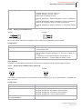
5.5.1 Status Messages
1999
100
tCbr
100
Status messages in case of alarm status or certain operating status will be al-ternately displayed with the actual value as additional information.
Display
Meaning
tCbr
Sensor break
x
Control thermocouple or wiring.
tCrC
Sensor incorrect polarity
x
Thermocouple wiring wrong. Correct
wiring.
IdE
Identification error
x
Cool zone down and then start identifi-cation again.
drl
Temperature drift
x
Determination of heating control para-meters can not start because the
zone was influenced by another zone
at identification. Start identification
again.
Id
Identification heating
x
IdC
Identification cooling
x
IdS
Start up phase automatic adaptation of
cooling
x
mAnU
Manual mode
x
AL
Measuring range exceeded (tempera-ture alarm)
x
Control heating unit and power control-ler (e.g. SSR).
Control if the sensor related with the
heating unit is connected with the con-troller.
SSr
Current alarm heating off
x
Control power controller (e.g. SSR).
Control if the current transformer related to the heating unit is connected with
the controller.
tCSC
Sensor alarm
x
Control thermocouple wiring.
Control parameter setting Ó[P023]tC.ti
- Testing Period for Manual Short Circuit Supervision of Sensor (page 30)
and Ó[P022]tC.AL - Autom. Short Circuit Supervision of Sensor (page 30).
rAmP
Ramp
x
SP4
Setpoint Value 4
x
SP3
Setpoint Value 3
x
SP2
Setpoint Value 2
x
Ar.
Automatic ramp slowest zone
x
Ar
Automatic ramp
x
ArE
Error automatic ramp
x
ArE.
Error automatic ramp slowest zone
x
Err1
Error in calibration data
x
Send controller to PSG Plastic Service
GmbH.
Err2
Error in attributes
x
Send controller to PSG Plastic Service
GmbH.
Technical changes reserved
Rev. 1.01.07
Alarm
Status
Fault Correction
PSG Plastic Service GmbH
Operating instructions ETR45&ETR46
Display
Meaning
Err3
Error in channel data
HoFF
Actuator deactivated
Alarm
Status
x
Fault Correction
Send controller to PSG Plastic Service
GmbH.
x
Technical changes reserved
Rev. 1.01.07
27
28
Chapter 6
Configuration / Setting
6
Configuration / Setting
The parameters for configuration and setting of the
controller are functionally grouped.
It depends on the unblocking of a parameter whether it
is visible and/or changeable. The unblocking is done on
system level where all parameters are visible and
chan-geable.
Ú The factory-made basic setting is marked
with a bracket (e.g. [on]).
Ú For some parameters the value range ex-ceeds the display range of the LED (9999
or 999.9). The complete value range is
only adjustable via serial interface or
CAN-Bus interface.
Ú Temperature parameters are specified in
°C by default. They apply for °F as well.
[P005]Cur.t - Tolerance Band of Heater Current
Value range: 0...100% [20]
Tolerance band around Ó[P004]Cur.S - Set Point of
Heater Current (page 28) for supervision of heating current.
[P006]ZonE - Status of Zone
Activation/Deactivation of zone.
oFF
Zone deactivated
Ú No control signal is generated (degree of operation 0%)
Ú The control algorithm is initialized
Ú No alarm supervision
[on]
Zone activated
Ú no control signal is generated (degree of operation
0%)
Ú the control algorithm is initialized
Ú no other alarm except the heating circuit alarm is su-pervised
[P007]Li.1 - Temperature Limit 1
Value range: -999.0...1500.0 [5]
The zone can be supervised by four temperature limit
values.
With the four associated parameters Ó[P041]Li.1d Definition of Temperature Limit 1 (page 32) to
Ó[P044]Li.4d - Definition of Temperature Limit 4 (page
32) the function of the limit value is determined.Ó[P044]Li.4d - Definition of Temperature Limit 4
(page 32)
The setting of the unit for a set point (°C or °F) is done
by parameter Ó[P055]CELS - Temperature Unit (page
33).
[P008]Li.2 - Temperature Limit 2
Value range: -999.0...1500.0 [-5]
Ø[P007]Li.1 - Temperature Limit 1
[P002]mAnU - Manual Mode
[P009]Li.3 - Temperature Limit 3
Value range: -999.0...1500.0 [0]
Ø[P007]Li.1 - Temperature Limit 1
6.1 Main functions
[P001]SP - Set Point
Value range: [0.0]...1500.0
At 0°C/32°F
on
[oFF]
Manual mode active
In manual mode the control is deactivated.
The manual entered actuating variable
Ó[P003]Out - Degree of Operation (page 28)
is sent to the control outputs.
Manual mode for example is used in case of a
defect at the sensor when there is no actual
temperature value for control and the control
function for the zone has to be maintained.
Controller is in control mode (manual mode
deactivated).
[P003]Out - Degree of Operation
Value range: -100...100% [0%]
Actuating variable. In control mode calculated by the
controller, in manual mode entered by the operator.
Ø[P021]AmAn - Automatic Manual Mode
[P004]Cur.S - Set Point of Heater Current
Value range: [0.0]...999.0 A
The measured heater current is compared with the set
point. The set point is manually or by automatic current
transfer (ÓInformation Level (page 20)) entered.
Technical changes reserved
Rev. 1.01.07
[P010]Li.4 - Temperature Limit 4
Value range: -999.0...1500.0 [0]
Ø[P007]Li.1 - Temperature Limit 1
[P011]SP.2 - Set Point 2
Value range: -999.0...1500.0 [0]
The second set point is activated by a digital input or by
a timer.
The same prerequisites apply accordingly to
Ó[P001]SP - Set Point (page 28).
[P012]SP.3 - Set Point 3
Value range: [0.0] ... 1500.0
Ø[P011]SP.2 - Set Point 2
[P013]SP.4 - Set Point 4
Value range: [0.0] ... 1500.0
Ø[P011]SP.2 - Set Point 2
[P014]rAP.t - Temperature Ramp
Value range: -999.0...999.0 °C/Minute [0]
PSG Plastic Service GmbH
Operating instructions ETR45&ETR46
Changes of the set point are not directly made but by
the adjusted ramp value.
SP
=0
Temperature ramp deactivated
>0
Temperature ramp at set point increase acti-vated
<0
Temperature ramp at set point increase and
decrease activated
In the set point display the set point of the actual ramp
is displayed.
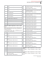
In the following diagram a change of a set point
from 50°C to 120°C with a temperature ramp
of 10°C/Minute is shown.
120
°C
[P016]rAP.G - Temperature Band of Autom. Temperature Ramp
Value range: 2.0...25.5 K [5.0]
Maximal tolerable difference between actual value and
set point of ramp during [P015]rAP.A - Automatic Temperature Ramp.
110
100
90
80
70
SP
60
[P017]t1 - Process Timer 1
Value range: [0]...9999 seconds
Four timers are available to carry out a sequence of
functions. The definition, how the timers operate, is de-termined by the parameters [P090]t1.d1 - Mode of Operation of Timer 1, Definition 1 to [P097]t4.d2 - Mode of
Operation of Timer 4, Definition 2.
[P018]t2 - Process Timer 2
Value range: [0]...9999 seconds
Ø[P017]t1 - Process Timer 1
50
[P015]rAP.A - Automatic Temperature Ramp
[oFF]
Automatic ramp deactivated
on
Consistent heating of several controllers.
Prerequisites:
Ú Controller with CAN-Bus interface
Ú Controller is connected with other control-lers which should be heated consistent. The
allocation is done by the group function.
Controllers with the same [P039]GP.nr Group Number are heated consistent during
active automatic temperature ramp.
The automatic temperature ramp only works
after the first change of the set point after
switch-on of the controller. The zone with the
slightest rate of rise of temperature is the lea-ding zone and defines the set point of the ramp
for all other zones. 15 K before reaching the
set point the automatic temperature ramp is
completed.
The calculation of the control parameters by
the function identification heating is not affec-ted by the automatic temperature ramp.
[P019]t3 - Process Timer 3
Value range: [0]...9999 seconds
Ø[P017]t1 - Process Timer 1
[P020]t4 - Process Timer 4
Value range: [0]...9999 seconds
Ø[P017]t1 - Process Timer 1
[P021]AmAn - Automatic Manual Mode
on
Is an invalid measured value (due to sensor
break) detected during control mode, the con-troller switches automatically over to manual
mode. The last averaged degree of operation
determined by the controller is used as the
new degree of operation.
[oFF]
Function deactivated
Technical changes reserved
Rev. 1.01.07
29
30
Chapter 6
Configuration / Setting
[P022]tC.AL - Autom. Short Circuit Supervision of
Sensor
on
The function supervises the status and the wi-ring of the sensor of short circuit.
The function is calculated by means of the actual value, the degree of operation and a
Ó[P028]H.Ct - Sampling Time of Heating
(page 30) dependent time. This assures the
detection of already existing as well as suddenly arising short circuits.
A short circuit alarm of a sensor is displayed, if
[P030]C.td - Derivative Time of Cooling
Value range: 0...2000 seconds [50]
[P031]C.ti - Integral Time of Cooling
Value range: 0...2000 seconds [50]
[P032]C.Ct - Sampling Time of Cooling
Value range: 0.2...90.0 seconds [1.0]
[P033]IdE.H - Identification Heating
[on]
Ú after a sampling time dependent time no
temperature rising is detected although the
controller outputs the maximum degree of
operation.
Ú a sudden drop of temperature is detected.
After detection of a short circuit of the sensor
tCSC is shown in the actual value display and
the zone is deactivated. The zone can be ac-tivated by the acknowledgement of the alarms
(ÓInformation Level (page 20)).
[oFF]
Function deactivated
[P023]tC.ti - Testing Period for Manual Short Circuit
Supervision of Sensor
Value range: [0]...999 seconds
Is the temperature increase after the expiration of the
testing period not 5K, although the controller outputs
the maximum degree of operation, a short circuit alarm
was detected.
Ú a reset of a zone (Ó[P006]ZonE - Status of
Zone (page 28) = off)
Ú or switch-on of controller
Ú or after setpoint value 0°C/32K
are calculated during heating-up.
During the identification phase Id and actual
value are shown alternately in the display.
oFF
on
The function only operates on setting
Ó[P048]CooL - Heating/Cooling (page
32)=on.
The control parameters Cooling are automati-cally determined after completion of
Ó[P033]IdE.H - Identification Heating (page
30).
The control parameters of cooling are calcula-ted according to the actual value pattern
while the output is set to the least degree of
operati-on. During identification phase Id- is
shown in the display.
After completion of the calculation of the con-trol parameters the controller operates with
the active set point again.
[oFF]
After completion of the identification Heating
no identification Cooling is executed.
[P024]APPL - Application
Without function.
6.2 Control parameter
This parameter group consists of the control parame-ters and the parameters that affect the automatic con-trol parameter calculation.
[P025]H.Pb - Proportional Band of Heating
Value range: 0.0...25.5% [6.5]
[P027]H.ti - Integral Time of Heating
Value range: 0...2000 seconds [50]
[P035]idE.L - Loop Control
on
During identification phase Heating the control
response at reaching the set point is additio-nally considered and if necessary a correction
of the control parameters of heating is perfor-med.
[oFF]
Function deactivated
[P028]H.Ct - Sampling Time of Heating
Value range: 0.2...90.0 seconds [0.2]
[P029]C.Pb - Proportional Band of Cooling
Value range: 0.0...25.5% [6.5]
Technical changes reserved
Rev. 1.01.07
Function deactivated
No parameter calculation for control parame-ters of heating is done during the heating up
phase. The heating is done due to the adju-sted set point.
[P034]IdE.C - Identification Cooling after Identification Heating
The zone is deactivated (degree of operation 0%). In
the actual value display tCSC is shown. The zone can
be activated by the acknowledgement of the alarm.
[P026]H.td - Derivative Time of Heating
Value range: 0...2000 seconds [50]
The control parameters Heating are calcula-ted after the first change of the set point grea-ter
than 50K after...
PSG Plastic Service GmbH
Operating instructions ETR45&ETR46
[P036] SP.Cb - Set Point Cutback
Value range: [0]...25.5 K
The function only operates on setting Ó[P035]idE.L Loop Control (page 30)=on.
The set point cutback function is embedded to prevent
an overshoot in the identification phase. The calculati-on of the control parameters of heating is performed
by a set point cutback reduced temperature set point.
The-reafter the controller operates with the temperature
set point.
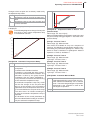
In the following diagram a complete trend (actual / set point / value and degree of operation)
of an automatic control parameter calculation
is described. The trend was recorded with the
following parameter setting:
Ú Ó[P033]IdE.H - Identification Heating (page 30) = on
Ú Ó[P034]IdE.C - Identification Cooling after Identification Heating (page 30) = on
Ú Ó[P035]idE.L - Loop Control (page 30) = on
Ú Ó[P036] SP.Cb - Set Point Cutback (page 31) = off
Ú Ó[P036] SP.Cb - Set Point Cutback (page 31) = 20
150
3
SP
°C
2
4
5
2
100
50
1
Actual
ue/
val-
0
100
%
SP
Setpoint
0
-100
[P037]C.Con - Control Parameter Cooling constant
after Identification Heating
In accordance with the dimensioning of the efficiency of
heating and of cooling at zones the control parameters
Cooling can generally be derived from the control para-meters Heating.
on
The control parameters Cooling are not deter-mined after identification Heating.
[oFF]
Is the function deactivated, the control para-meters Cooling are derived from the control parameters Heating after identification Hea-ting.
6.3 Group functions
To use the controller overall and operating functions
the controller has to be allocated to a group.
Prerequisite for all group function is the net-working of the controllers by CAN-Bus inter-face.
[P038]GP.rt - Remote Group
Value range: [0]...32
With the remote operation function the operation of
multiple controllers is facilitated. For all controllers allo-cated to one remote operation group the operations on
information level are synchronously processed. It is
ne-gligible on which controller of the remote operation
group the operation is processed.
[P039]GP.nr - Group Number
Value range: [0]...32
For all controllers allocated to one remote operation
group
Ú the automatic ramp
Ú the timers
are controller overall synchronized.
Degree of
Operation
1 - After set point jump from 0°C to 140°C the control
parameters of heating are calculated during heating up.
2 - 20°C (set point cutback) before reaching the set
point of 140°C the calculation of the control parameters
of heating is completed.
3 - The controller operates with the adjusted set point.
4 - After the actual value has reached the adjusted set
point, the calculation of the control parameters of cooling is started.
5 - After the calculation of the control parameters of
cooling is completed, the controller operates with the
adjusted set point.
[P040]GP.Fu - Group Function
Value range: [0]...255
6.4 Definition of Temperature Limit Values
This parameter group determines how the temperature
limit values adjusted by the main functions are evalu-ated.
A combination of several alarms can be
used for one temperature limit value. In this
case the sum of all identifiers has to be en-tered for the parameter.
5 (is equivalent to the sum of identifiers 1
and 4) is entered when an alarm should be
generated on exceeding an absolute alarm
limit value.
Technical changes reserved
Rev. 1.01.07
31
32
Chapter 6
Configuration / Setting
The default value 0 defines a relative alarm
limit value.
[P041]Li.1d - Definition of Temperature Limit 1
Value range: [0]...255
Identification
Alarm mode
1
Absolute alarm limit value.
Otherwise: Alarm limit value relative to
set point.
2
Alarm is generated after reaching the
alarm value first time.
Otherwise: Alarm is always generated.
4
Only valid for absolute alarm limit values.
Alarm on actual value > limit value.
Otherwise: Alarm on actual value < limit
value.
8
Without function.
16
Only valid for ETR46:
Supervise measuring input A.
32
Only valid for ETR46:
Supervise measuring input B.
64
Only valid for ETR46:
Supervise measuring input C.
128
Hysteresis Limit Value Li1/Li2 for [P041]
and [P042]
Hysteresis Limit Value Li3/Li4 for [P043]
and [P044]
ØAlarm Hysteresis Function
[P042]Li.2d - Definition of Temperature Limit 2
Value range: [0]...255
Ø[P041]Li.1d - Definition of Temperature Limit 1
[P043]Li.3d - Definition of Temperature Limit 3
Value range: [0]...255
Ø[P041]Li.1d - Definition of Temperature Limit 1
[P044]Li.4d - Definition of Temperature Limit 4
Value range: [0]...255
Ø[P041]Li.1d - Definition of Temperature Limit 1
6.5 Configuration of Base functions
[P045]Out.H - Maximum Degree of Operation Heating
Value range: 0...[100]%
Upper limitation of degree of operation in control mode.
[P046]Out.C - Maximum Degree of Operation of
Cooling
Value range: [-100]...0 %
Lower limitation of degree of operation in control mode.
Technical changes reserved
Rev. 1.01.07
[P047]Out.m - Maximum Degree of Operation in
Manual Mode
Value range: -100...[100]%
Upper limitation of degree of operation in
Ó[P002]mAnU - Manual Mode (page 28).
Function also active with Ó[P022]tC.AL - Autom. Short
Circuit Supervision of Sensor (page 30).
[P048]CooL - Heating/Cooling
on
Controller operates as three-position control-ler (Heating/Cooling).
[oFF]
Controller operates as two-position controller
(Heating).
[P049]rEL.H - Relay Output Heating
If degree of operation > 0...
on
Ú ... only one on/off switching operation at
control output during one sampling cycle.
Ú ... sampling time is set to minimum 10 seconds.
[oFF]
... output of degree of operation with quickly
clocked, short pulses (e.g. output for Solid
State Relays).
[P050]rEL.C - Relay Output Cooling
If degree of operation < 0...
[on]
Ú ... only one on/off switching operation at
control output during one sampling cycle.
Ú ... sampling time is set to minimum 10 seconds.
oFF
... output of degree of operation with quickly
clocked, short pulses (e.g. output for Solid
State Relays).
[P051]SP.Lo - Lower Set Point Limit
Value range: [0.0]...1500.0 °C
Minimum adjustable set point.
[P052]SP.Hi - Upper Set Point Limit
Value range: 0.0...1500.0 °C [500.0]
Maximum adjustable set point.
[P053]Cur.d - Current Supervision Function
Value range: 0...99
Prerequisite: current transformer connected.
0
Deactivated current monitoring
[1]
Measuring cycle 30 seconds.
Analysis of currents > 0.3 A
2
Measuring cycle 30 seconds.
Analysis of currents > 0.2 A
3
Measuring only for degree of operation > 0%
Measuring cycle 30 seconds.
Analysis of currents > 0.3 A
PSG Plastic Service GmbH
Operating instructions ETR45&ETR46
4
Measuring only for degree of operation > 0%
Measuring cycle 30 seconds.
Analysis of currents > 0.2 A
8
Master in Master-/Slave current measuring.
Measuring cycle 30 seconds.
9
AL1
Output switched, if at least one alarm defined
by Ó[P082]A1.d1 - Alarm Flag 1, Definition 1
(page 36) or Ó[P083]A1.d2 - Alarm Flag 1,
Definition 2 (page 36) is active.
AL2
Output switched, if at least one alarm defined
by Ó[P084]A2.d1 - Alarm Flag 2, Definition 1
(page 36) or Ó[P085]A2.d2 - Alarm Flag 2,
Definition 2 (page 36) is active.
AL3
Output switched, if at least one alarm defined
by Ó[P086]A3.d1 - Alarm Flag 3, Definition 1
(page 36) or Ó[P087]A3.d2 - Alarm Flag 3,
Definition 2 (page 36) is active.
AL4
Output switched, if at least one alarm defined
by Ó[P088]A4.d1 - Alarm Flag 4, Definition 1
(page 36) or Ó[P089]A4.d2 - Alarm Flag 4,
Definition 2 (page 36) is active.
AL1-
Like ÓAL1 (page 33). Output inverted.
AL2-
Like ÓAL2 (page 33). Output inverted.
AL3-
Like ÓAL3 (page 33). Output inverted.
AL4-
Like ÓAL4 (page 33). Output inverted.
t1
Output switched, if timer 1 active
t2
Output switched, if timer 2 active
t3
Output switched, if timer 3 active
t4
Output switched, if timer 4 active
Slave in Master-/Slave current measuring.
Measuring cycle 30 seconds.
11-19 Like 1 ... 9,
only with measuring cycle 15 seconds.
21-29 Like 1 ... 9
only with measuring cycle 10 seconds.
[P054]Cur.E - Final Value of Measurement Range of
Current Supervision
Value range: 0...999.9% [100.0]
Scaling of the current measuring input when the output
signal of the current transformer is different from 42mV/
A or the feed line of the heating element is repeatedly
led through the current transformer.
[P055]CELS - Temperature Unit
C
Celsius
F
Degrees Fahrenheit.
LED °F on the front of the controller is illumina-ted.
t1-
Output switched, if timer 1 is not active
6.6 Display
t2-
Output switched, if timer 2 is not active
The displays are adjusted by means of this parameter
group.
t3-
Output switched, if timer 3 is not active
t4-
Output switched, if timer 4 is not active
[P056]deCP - Display of Format of Temperature Values
Value range: 0.1/[1.0]
Display / data entry of all temperature values by LED
display with or without decimal place. Entry by serial
data interface RS485 and CAN-Bus interface always in
format 0.1.
[P057]dmAn - Display in Manual Mode
[out]
Display of degree of operation
tEmP Display of actual value
6.7 Configuration of Hardware
The mode of operation of in- and outputs at the control-ler is adjusted by means of this parameter group. The
setting in general has to be done once at start-up.
[P058]dO.1 - Mode of Operation of Digital Output 1
oFF
Output without function
[HEAt] Output of control signal Heating
Cool
Co.OP Open valve
For valve control. Only degree of operation
changes are output.
Not at [P066], [P067]
Co.CL
Close valve
For valve control. Only degree of operation
changes are output.
Not at [P066], [P067]
[P059]dO.2 - Mode of Operation of Digital Output 2
Ø[P058]dO.1 - Mode of Operation of Digital Output 1
Default value [CooL]
[P060]dO.3 - Mode of Operation of Digital Output 3
Ø[P058]dO.1 - Mode of Operation of Digital Output 1
Default value [AL1]
[P061]dO.4 - Mode of Operation of Digital Output 4
Ó[P058]dO.1 - Mode of Operation of Digital Output 1
(page 33)
Default value [AL2]
Output of control signal Cooling
Technical changes reserved
Rev. 1.01.07
33
34
Chapter 6
Configuration / Setting
[P062]dIn.1 - Mode of Operation of Digital Input 1
Is digital input 1 active...
[oFF]
Digital input without function
P.on
... it is indicated to the controller that the power controller for heating is connected.
Is digital input 1 inactive the control is
stopped, no control signal and no current toleran-ce alarms are generated.
The factory-made default setting depends on the de-vice specification. For controllers without options the
default setting is in each case oFF.
[oFF]
Option A not available
rS
Interface RS485
dI
Digital input
dO
Digital output
AO
Analog output 0...10VDC/0...20mA
P.oFF
... it is indicated to the controller that the power controller for heating is disconnected.
SP2.A
... the controller operates with the 2nd set
point.
SP3.A
... the controller operates with the 3rd set
point.
SP4.A
... the controller operates with the 4th set
point.
[oFF]
Option B not available
SP2.r
... the set point is increased or decreased by
the 2nd set point.
CAn
CAN-Bus
dI
Digital input
SP3.r
... the set point is increased or decreased by
the 3rd set point.
dO
Digital output
AO
Analog output 0...10VDC/0...20mA
SP4.r
... the set point is increased or decreased by
the 4th set point.
AO.O Analog output 2...10VDC/4...20mA
H.oFF
... the heating
switched off.
output
is
permanently
H.on
... the heating
switched on.
output
is
permanently
C.oFF
... the cooling
switched off.
output
is
permanently
C.on
... the cooling
switched on.
output
is
permanently
SP.bA
SP.br
AL.CL
... the activated and stored alarm outputs are
reset.
t1
... timer 1 started by switch on edge.
t2
... timer 2 started by switch on edge.
t3
... timer 3 started by switch on edge.
t4
... timer 4 started by switch on edge.
t1-
... timer 1 started by switch off edge.
t2-
... timer 2 started by switch off edge.
t3-
... timer 3 started by switch off edge.
t4-
... timer 4 started by switch off edge.
iLoC
... entry by membrane keypad is locked. No
entry by membrane keypad is feasible.
[P063]dIn.2 - Mode of Operation of Digital Input 2
Ø[P062]dIn.1 - Mode of Operation of Digital Input 1
[P064]OPt.A - Definition of Option A
Setting of function of option A.
Technical changes reserved
Rev. 1.01.07
AO.O Analog output 2...10VDC/4...20mA
[P065]OPt.b - Definition of Option B
Setting of function of option B.
The factory-made default setting depends on the de-vice specification.
[P066]dO.A - Mode of Operation of Digital Output
Option A
Prerequisite: Option A is configured as digital output.
Ø[P058]dO.1 - Mode of Operation of Digital Output 1
[P067]dO.b - Mode of Operation of Digital Output
Option B
Prerequisite: Option B is configured as digital output.
Ø[P058]dO.1 - Mode of Operation of Digital Output 1
[P068]dIn.A - Mode of Operation of Digital Input Option A
Prerequisite: Option A is configured as digital input
(ÓdI (page 34)).
Ø[P062]dIn.1 - Mode of Operation of Digital Input 1
[P069]dIn.b - Mode of Operation of Digital Input Option B
Prerequisite: Option B is configured as digital input (ÓdI
(page 34)).
Ø[P062]dIn.1 - Mode of Operation of Digital Input 1
[P070]AO.A - Mode of Operation of Analog Output
Option A
Prerequisite: Option A is configured as analog output
(ÓAO (page 34) or ÓAO.O (page 34)).
[oFF]
Output without function
out.H
Output of degree of operation of heating.
out.C
Output of degree of operation of cooling.
SEn.C Output of value defined by Ó[P073]SEn.C Measuring Input for Control (page 35).
PSG Plastic Service GmbH
Operating instructions ETR45&ETR46
S.C b
Output of value defined by Ó[P073]SEn.C Measuring Input for Control (page 35), scaled
by para-meter Aib.L and Aib.H.
S.C C Output of value defined by Ó[P073]SEn.C Measuring Input for Control (page 35), scaled
by para-meter AiC.L and AiC.H.
IntF
Output of specified value by serial interface or
CAN-Bus.
[P071]AO.b - Mode of Operation of Analog Output
Option B
Prerequisite: Option B is configured as analog output
(ÓAO (page 34) or ÓAO.O (page 34)).
Ø[P070]AO.A - Mode of Operation of Analog Output
Option A
[P072]SEn - Sensor Type of Measuring Input A
L
Fe-CuNi Type L
[J]
Fe-CuNi Type J
niCr
Ni-CrNi Type K
Pt
Resistance thermometer Pt100
[P073]SEn.C - Measuring Input for Control
Parameter is only valid for ETR46.
Presetting which of the three actual values or a
combination of these are used for control.
[A]
Input A
b
Input B
C
Input C
A-b
Difference (measuring input A - measuring in-put B)
b-A
Difference (measuring input B - measuring in-put A)
A-C
Difference (measuring input A - measuring in-put C)
C-A
Difference (measuring input C - measuring in-put C)
C-b
Difference (measuring input C - measuring in-put B)
b-C
Difference (measuring input B - measuring in-put C)
For measuring input B and C the limit ranges confi-gured by AIb.L, Aib.H, AiC.L und AiC.H are valid.
[P074]Sen.S - Measuring Input for Presetting of Set
Point
Parameter is only valid for ETR46.
[oFF]
Presetting of set point by keypad, serial inter-face or CAN-Bus.
A
Presetting of set point by measuring input A.
b
Presetting of set point by measuring input B.
C
Presetting of set point by measuring input C.
Exceeds the input value the measurement range, the
current set point of control is set to Ó[P001]SP - Set
Point (page 28), otherwise the input value is taken for
current set point of control. The function "set point value
change" is executed for a set point change > 0.5 °C.
For measuring input B and C the input ranges confi-gured by Aib.L, Aib.H, AiC.L und AiC.H are valid.
[P075]oFF.A - Offset of Measuring Input A
Value range: -100.0...100.0 [0.0]
Correction of the actual value display of measuring input A dependent on temperature unit. E.g. for compensation of the measurement error caused by the output
resistance of a resistance thermometer Pt100.
Actual value display = measured value + ’Offset of
Measuring Input A’
[P076]oFF.b - Measurement range of Measuring Input B
[0-10] Measurement range 0...10 VDC
2-10
Measurement range 2...10 VDC
[P077]oFF.C - Measurement range of Measuring Input C
0-20
Measurement range 0...20 mA
[4-20] Measurement range 4...20 mA
[P078]Aib.L - Lower Display Limit of Measuring Input B
Value range: -100.0...1500.0 [0.0]
AIb.h
AIC.h
AIb.L
AIC.L
0/2 VDC
0/4 mA
10 VDC
20 mA
Defines the display value of measuring input B for a
measured value of 0 respectively 2 VDC or 0 respec-tively 4mA.
The characteristic of the display values for measuring
input B is defined by Ó[P079]Aib.H - Upper Display
Limit of Measuring Input B (page 36).
The set point of control is linear output between AI*.L
and AI*.H. For the set point of control beneath AI*.L, 0
is output; above AI*.H, maximal value is output.
Technical changes reserved
Rev. 1.01.07
35
36
Chapter 6
Configuration / Setting
[P079]Aib.H - Upper Display Limit of Measuring Input B
Value range: -100.0...1500.0 [999.9]
Ø[P078]Aib.L - Lower Display Limit of Measuring Input
B
[P080]AiC.L - Lower Display Limit of Measuring Input C
Value range: -100.0...1500.0 [0.0]
Ø[P078]Aib.L - Lower Display Limit of Measuring Input
B
Identification
Alarm
4
Hysteresis Limit Value Li3/Li4
ØAlarm Hysteresis Function
8
Hysteresis Limit Value Li1/Li2
ØAlarm Hysteresis Function
16
Without function
32
Without function
64
Alarm flag can be acknowledged
128
Alarm flag storing
[P081]AiC.H - Upper Display Limit of Measuring Input C
Value range: -100.0...1500.0 [999.9]
Ø[P078]Aib.L - Lower Display Limit of Measuring Input
B
[P084]A2.d1 - Alarm Flag 2, Definition 1
Value range: 0...255 [8]
Ø[P082]A1.d1 - Alarm Flag 1, Definition 1
6.8 Configuration of Alarm Flags
[P085]A2.d2 - Alarm Flag 2, Definition 2
Value range: 0...255 [0]
Ø[P083]A1.d2 - Alarm Flag 1, Definition 2
The controller offers a total of four alarm flags.
The status of the alarm flags is defined by two parame-ters (definition groups). Is at least one defined process
alarm active, the status of the alarm flag equals 1. The
status of the alarm flags can be shown on the digital
outputs.
The function of the alarm flag is defined by the alarm
identifiers set (0 = nothing set).
[P082]A1.d1 - Alarm Flag 1, Definition 1
Value range: 0...255 [4]
[P086]A3.d1 - Alarm Flag 3, Definition 1
Value range: 0...255 [2]
Ø[P082]A1.d1 - Alarm Flag 1, Definition 1
[P087]A3.d2 - Alarm Flag 3, Definition 2
Value range: 0...255 [0]
Ø[P083]A1.d2 - Alarm Flag 1, Definition 2
By setting of A3.d* the status of the alarm flag
is output on the digital outputs and on the LED
B and/or E (output cooling / alarm output 3).
Identification
Alarm
1
Current alarm on heating off - current is
measured for degree of operation 0%
2
Current tolerance alarm
4
Ó[P007]Li.1 - Temperature Limit 1 (page
28)
[P089]A4.d2 - Alarm Flag 4, Definition 2
Ø[P083]A1.d2 - Alarm Flag 1, Definition 2
Value range: 0...255 [0]
8
Ó[P008]Li.2 - Temperature Limit 2 (page
28)
6.9 Definition of Timers
16
Ó[P009]Li.3 - Temperature Limit 3 (page
28)
32
Ó[P010]Li.4 - Temperature Limit 4 (page
28)
64
Sensor short-circuit
128
Sensor break/sensor incorrect polarity
[P083]A1.d2 - Alarm Flag 1, Definition 2
Default value [0]
[P088]A4.d1 - Alarm Flag 4, Definition 1
Value range: 0...255 [1]
Ø[P082]A1.d1 - Alarm Flag 1, Definition 1
The controller offers a total of four timers where com-plex sequences of functions can be realized.
The function and how the timer acts are defined by two
parameters.
[P090]t1.d1 - Mode of Operation of Timer 1, Definition 1
With the first parameter of a timer is defi-ned which function is performed when the timer is ac-tive.
[oFF]
No function.
Identification
Alarm
P.on
The power controller of heating is switched
on.
1
Error during identification phase / drift
P.oFF
2
Actual value greater than end of measure-ment range
The power controller of heating is switched
off.
Technical changes reserved
Rev. 1.01.07
PSG Plastic Service GmbH
Operating instructions ETR45&ETR46
SP2.A
The controller operates with the 2nd set
point.
SP3.A
The controller operates with the 3rd set
point.
SP4.A
The controller operates with the 4th set
point.
SP2.r
The set point is increased or decreased by
the 2nd set point.
SP3.r
The set point is increased or decreased by
the 3rd set point.
SP4.r
The set point is increased or decreased by
the 4th set point.
H.oFF
Heating output is switched off.
H.on
Heating output is switched on.
C.oFF
Cooling output is switched off.
C.on
Cooling output is switched on.
AL.t2
Timer is started when the actual value reaches
the 5K band around the set point directly after
start of the controller.
After termination: Start of timer 2.
AL.t3
Timer is started when the actual value reaches
the 5K band around the set point directly after
start of the controller.
After termination: Start of timer 3.
AL.t4
Timer is started when the actual value reaches
the 5K band around the set point directly after
start of the controller.
After termination: Start of timer 4.
L.t1
Timer is started when the actual value reaches
the 5K band around the set point.
After termination: Start of timer 1.
L.t2
Timer is started when the actual value reaches
the 5K band around the set point.
After termination: Start of timer 2.
L.t3
Timer is started when the actual value reaches
the 5K band around the set point.
After termination: Start of timer 3.
L.t4
Timer is started when the actual value reaches
the 5K band around the set point.
After termination: Start of timer 4.
AL
Timer is started when the actual value reaches
the 5K band around the set point directly after
start of the controller.
L
Timer is started when the actual value reaches
the 5K band around the set point.
Timer is started when set point > 100 °C and
actual value < 90 °C.
SP.bA
SP.br
AL.CL
Stored alarms outputs are reset.
[P091]t1.d2 - Mode of Operation of Timer 1, Definition 2
With the second parameter of a timer is defined how the
timer is started and which action is per-formed after termination of the timer.
*) For parameter t.rES = Auto, a Soft-Reset has the
same effect like controller start.
[oFF]
Timer is not started.
Auto
Timer is automatically started after controller
start *).
AS
A.t1
Timer is automatically started after controller
start *).
After termination: Start of timer 1.
AS.t1 Timer is started when set point > 100 °C and
actual value < 90 °C.
After termination: Start of timer 1.
A.t2
Timer is automatically started after controller
start *).
After termination: Start of timer 2.
AS.t2 Timer is started when set point > 100 °C and
actual value < 90 °C.
After termination: Start of timer 2.
A.t3
Timer is automatically started after controller
start *).
After termination: Start of timer 3.
AS.t3 Timer is started when set point > 100 °C and
actual value < 90 °C.
After termination: Start of timer 3.
A.t4
Timer is automatically started after controller
start *).
After termination: Start of timer 4.
AS.t4 Timer is started when set point > 100 °C and
actual value < 90 °C.
After termination: Start of timer 4.
t1
After termination: Start of timer 1.
t2
After termination: Start of timer 2.
t3
After termination: Start of timer 3.
t4
After termination: Start of timer 4.
[P092]t2.d1 - Mode of Operation of Timer 2, Definition 1
Ø[P090]t1.d1 - Mode of Operation of Timer 1, Definition 1
AL.t1
Timer is started when the actual value reaches
the 5K band around the set point directly after
start of the controller.
After termination: Start of timer 1.
[P093]t2.d2 - Mode of Operation of Timer 2, Definition 2
Ø[P091]t1.d2 - Mode of Operation of Timer 1, Definition 2
Technical changes reserved
Rev. 1.01.07
37
38
Chapter 6
Configuration / Setting
[P094]t3.d1 - Mode of Operation of Timer 3, Definition 1
Ø[P090]t1.d1 - Mode of Operation of Timer 1, Definition 1
[P095]t3.d2 - Mode of Operation of Timer 3, Definition 2
Ø[P091]t1.d2 - Mode of Operation of Timer 1, Definition 2
[P096]t4.d1 - Mode of Operation of Timer 4, Definition 1
Ø[P090]t1.d1 - Mode of Operation of Timer 1, Definition 1
[P097]t4.d2 - Mode of Operation of Timer 4, Definition 2
Ø[P091]t1.d2 - Mode of Operation of Timer 1, Definition 2
[P098]t.rES - Mode of Operation of Timer after SoftReset
A soft reset stands for a sensor break, a reset of a set
point to zero or a passivation of a zone.
[run]
Timer keeps on running.
StoP
Timer is stopped and reset.
Auto
Timer is stopped, reset and after soft reset
started again in case of t*.d2 = Auto and/or
A.**.
6.10 Configuration of Operation
[P099]Edit - Entry Mode Directly
[on]
After selection the parameters in operator and
system level can directly be changed by key-pad.
In this mode the direct data entry for degree of
operation/ set point value by decrease/increa-se button is feasible.
oFF
After selection the parameters in operator and
system level can only be changed after un-blocking by keypad by decrease/increase but-ton.
[P100]iLoc - Entry Lock on Info Level
on
No data entry on information level feasible.
[oFF]
Data entry on information level feasible.
[P110]ULoc - Entry Lock on User/System level
After restart of the device, all data entry except setpoint
value and degree of operation is automatically blocked.
The unlocking of user level USEr is done by entering
the value set here as code number (see chapter ÓEnter
Code Number (page 24)). The unlocking of system lev-
Technical changes reserved
Rev. 1.01.07
el SYS is done by entering the value set here +10 as
code number.
[0]
No entry on user/system level possible.
1-100 Entry on user/system level possible. Input
blocking is automatically reactivated 1 minute
after the last key operation.
PSG Plastic Service GmbH
Operating instructions ETR45&ETR46
6.11 Configuration of Data Interface
The two optional available data interfaces are confi-gured by means of this parameter group.
[P101]S.Adr - Address of serial interface
Address of device for communication via the serial data
interface with ÓPSGII-Protocol (page 39).
[P102]S.Pro - Protocol of Serial Interface
[PSG] PSGII-Protocol
rtU
Modbus RTU
Interface specifications are available on request.
[P103]S.bd - Baud Rate of Serial Interface
Value range: 1200, 2400, 4800, 9600, [19.2], 38.4
Transfer rate of serial interface.
[P104]S.Sto - Stop Bits of Serial Interface
Value range: [1]/2
Number of stop bits of serial data interface.
[P105]S.PAr - Parity of Serial Interface
Parity bit, for the detection of transfer errors.
[no]
No parity bit.
EvEn The parity bit complements the 1 bits in the bit
string to a even number of 1 bits.
odd
The parity bit complements the 1 bits in the bit
string to a odd number of 1 bits.
[P106]C.bAS - CAN base address
Value range: 0...127 [32]
Resulting Node id of the controller: C.bAS + S.Adr
[P107]C.bd - CAN baud rate
Value range: 78.8, 100, 125, [250], 500, 800, 1000
Transfer rate of CAN-Bus.
[P108]C.OP - CAN Auto Operational Mode
In case of networking of several controllers by CANBus without CAN-Bus-Master at least one controller
has to send out the auto operational command.
oFF
Controller sends no auto operational com-mand.
[Auto] Controller sends auto operational command
cyclical.
[P109]m.Adr - MODBUS address
Value range: 0...255 [1]
tus are shown exemplarily. To change all parameters
select ÓSystem Level (page 22).
6.12.1 Application Hot Runner Control
Start-up Function
After start the controller operates for a definite time with
the set point for start-up. Ó[P013]SP.4 - Set Point 4
(page 29) is used for this function.
Ú Define mode of operation for the start-up timer after
start of the controller:
Ó[P090]t1.d1 - Mode of Operation of Timer 1, Definition 1 (page 37) = SP4.A and Ó[P091]t1.d2 - Mode of
Operation of Timer 1, Definition 2 (page 37) = AL.t2
Ú Define period of start-up mode:
Ó[P017]t1 - Process Timer 1 (page 29) = 600 (seconds)
Ú Define temperature value on which the controller operates in start-up mode:
Ó[P013]SP.4 - Set Point 4 (page 29) = 100
Boost Function
In the boost mode the temperature set point is increased by an adjustable temperature value, e.g. to
heat up the hot runner nozzles before start of the pro-duction. The boost mode is automatically started after
start-up function or by a signal on the digital input 2 (on-ly ETR46) of the controller. For boost mode
Ó[P012]SP.3 - Set Point 3 (page 28) is used.
Ú Define mode of operation for the second digital input:
Ó[P063]dIn.2 - Mode of Operation of Digital Input 2
(page 34) = t2 (only ETR46)
Ú Define a temperature value that increases („boosts“)
the temperature:
Ó[P012]SP.3 - Set Point 3 (page 28)
Ú Define mode of operation for the boost timer:
Ó[P092]t2.d1 - Mode of Operation of Timer 2, Definition 1 (page 38) = SP3.r and Ó[P093]t2.d2 - Mode of
Operation of Timer 2, Definition 2 (page 38) = L
Ú Define period of boost mode:
Ó[P018]t2 - Process Timer 2 (page 29) = 300 (seconds)
Stand-by Function
If the digital input 1 is active, the controller operates
with the reduced set point.
Ú Define mode of operation of digital input 1:
Ó[P062]dIn.1 - Mode of Operation of Digital Input 1
(page 34) = SP2.r
Ú Define temperature value for lowering by:
Ó[P011]SP.2 - Set Point 2 (page 28) = 100.0
Alarm monitoring
6.12 Basic settings for Special Applications
The temperature controllers can easily be adapted to
any application. For some applications the parameter
modifications based on the factory-made delivery sta-Technical changes reserved
Rev. 1.01.07
39
40
Chapter 6
Configuration / Setting
An alarm is generated when the temperature value ex-ceeds the defined band around the temperature set
point.
Ú Define upper temperature limit:
Ó[P007]Li.1 - Temperature Limit 1 (page 28) = 5°C
Ú Define lower temperature limit:
Ó[P008]Li.2 - Temperature Limit 2 (page 28) = -5°C
Ú Define identifiers of alarm flag:
Ó[P082]A1.d1 - Alarm Flag 1, Definition 1 (page 36)
= 12
Ú Alarm flag should be generated on digital output:
Ó[P059]dO.2 - Mode of Operation of Digital Output 2
(page 33) = AL1
6.12.2 Application Extrusion
Three-point zone (Heating/Cooling)
Ú Activate cooling: Ó[P048]CooL - Heating/Cooling
(page 32) = on
Ú Activate auto tuning for cooling: Ó[P034]IdE.C - Identification Cooling after Identification Heating (page
30) = on
Besides the controller is preset for the operation with an
extruder.
6.12.3 Application Hot Air
To achieve optimal control results, the automatic calcu-lation of the heating control parameters should be de-activated and the heating control parameters should
be manually entered.
Ú Deactivate automatic calculation of heating control
parameters:
Ó[P033]IdE.H - Identification Heating (page 30) = off
Ú Set heating control parameters:
Ó[P025]H.Pb - Proportional Band of Heating (page
30) = 15
Ó[P026]H.td - Derivative Time of Heating (page 30) =
1
Ó[P027]H.ti - Integral Time of Heating (page 30) = 3
Ó[P028]H.Ct - Sampling Time of Heating (page 30) =
0.3
In case these control parameters are not leading to
an optimal result for your hot air zones, please con-tact PSG Plastic Service GmbH.
For a further adaptation of the heating control para-meters please watch the actual value as well as the
dedicated degree of operation.
6.12.4 Alarm Hysteresis Function
To generate an alarm dependent on the exceeding of
an absolute upper limit value, that is pending, as long
Technical changes reserved
Rev. 1.01.07
as an absolute lower limit value is not under-run, the
alarm hysteresis function can be used.
Alarm active
Alarm inactive
Li.2/Li.4
Li.1/Li.3
The function
Ú generates an alarm, even though Ó[P001]SP - Set
Point (page 28) = 0
Ú generates no alarm, when Ó[P006]ZonE - Status of
Zone (page 28) = oFF
To output the alarm on a digital output, it must be assi-gned to an alarm flag. The following setting must be
done for the alarm hysteresis function.
Ú Ó[P007]Li.1 - Temperature Limit 1 (page 28): set upper limit va-lue
Ú Ó[P008]Li.2 - Temperature Limit 2 (page 28): set lower limit value
Ú set Ó[P041]Li.1d - Definition of Temperature Limit 1
(page 32) = 128
Ú set Ó[P042]Li.2d - Definition of Temperature Limit 2
(page 32) = 128
Ú Alarm flag 1 should be used for example. Set
Ó[P083]A1.d2 - Alarm Flag 1, Definition 2 (page 36)
= 8.
Ú The alarm flag should be output on digital output 1 for
example. Set Ó[P058]dO.1 - Mode of Operation of
Digital Output 1 (page 33) = AL1.
Instead of the parameters [P007], [P008] and [P041],
[P042] also the parameters [P009], [P010] and [P043],
[P044] could be used. The used alarm flag (example
see above) Ó[P083]A1.d2 - Alarm Flag 1, Definition 2
(page 36) must be set to 4.
PSG Plastic Service GmbH
Operating instructions ETR45&ETR46
7
Appendix
7.1 Parameters/factory delivery status
Designation/characteristic analog
Value range (physical value)
mnemonic/parameter
Ó[P001]SP - Set Point
0...1500.0
Ó[P002]mAnU - Manual Mode
oFF, on
Ó[P003]Out - Degree of Operation
-100...100
Ó[P004]Cur.S - Set Point of Heater Current
0.0...999.0
Ó[P005]Cur.t - Tolerance Band of Heater Current
0...100
Ó[P006]ZonE - Status of Zone
oFF, on
Ó[P007]Li.1 - Temperature Limit 1
-999.0...1500.0
Ó[P008]Li.2 - Temperature Limit 2
-999.0...1500.0
Ó[P009]Li.3 - Temperature Limit 3
-999.0...1500.0
Ó[P010]Li.4 - Temperature Limit 4
-999.0...1500.0
Ó[P011]SP.2 - Set Point 2
-999.0...1500.0
Ó[P012]SP.3 - Set Point 3
-999.0...1500.0
Ó[P013]SP.4 - Set Point 4
-999.0...1500.0
Ó[P014]rAP.t - Temperature Ramp
-999.0...999.0
Ó[P015]rAP.A - Automatic Temperature Ramp
oFF, on
Ó[P016]rAP.G - Temperature Band of Autom. Tempera- 2.0...25.5
ture Ramp
Ó[P017]t1 - Process Timer 1
0...9999
Ó[P018]t2 - Process Timer 2
0...9999
Ó[P019]t3 - Process Timer 3
0...9999
Ó[P020]t4 - Process Timer 4
0...9999
Ó[P021]AmAn - Automatic Manual Mode
oFF, on
Ó[P022]tC.AL - Autom. Short Circuit Supervision of Sen- oFF, on
sor
Ó[P023]tC.ti - Testing Period for Manual Short Circuit Su- 0...999
pervision of Sensor
Ó[P024]APPL - Application
0...255
Ó[P025]H.Pb - Proportional Band of Heating
0.0...25.5
Ó[P026]H.td - Derivative Time of Heating
0...2000
Ó[P027]H.ti - Integral Time of Heating
0...2000
Ó[P028]H.Ct - Sampling Time of Heating
0.2...90.0
Ó[P029]C.Pb - Proportional Band of Cooling
0.0...25.5
Ó[P030]C.td - Derivative Time of Cooling
0...2000
Ó[P031]C.ti - Integral Time of Cooling
0...2000
Ó[P032]C.Ct - Sampling Time of Cooling
0.2...90.0
Ó[P033]IdE.H - Identification Heating
oFF, on
Ó[P034]IdE.C - Identification Cooling after Identification oFF, on
Heating
Ó[P035]idE.L - Loop Control
oFF, on
Ó[P036] SP.Cb - Set Point Cutback
0.0...25.5
Ó[P037]C.Con - Control Parameter Cooling constant after oFF, on
Identification Heating
Ó[P038]GP.rt - Remote Group
0...32
Ó[P039]GP.nr - Group Number
0...32
Ó[P040]GP.Fu - Group Function
0...255
Ó[P041]Li.1d - Definition of Temperature Limit 1
0...255
Ó[P042]Li.2d - Definition of Temperature Limit 2
0...255
Ó[P043]Li.3d - Definition of Temperature Limit 3
0...255
Ó[P044]Li.4d - Definition of Temperature Limit 4
0...255
Ó[P045]Out.H - Maximum Degree of Operation Heating 0...100
Ó[P046]Out.C - Maximum Degree of Operation of Cooling -100...0
Ó[P047]Out.m - Maximum Degree of Operation in Manual -100...100
Mode
Ó[P048]CooL - Heating/Cooling
oFF, on
Ó[P049]rEL.H - Relay Output Heating
oFF, on
Ó[P050]rEL.C - Relay Output Cooling
oFF, on
Ó[P051]SP.Lo - Lower Set Point Limit
0.0...1500.0
Ó[P052]SP.Hi - Upper Set Point Limit
0.0...1500.0
Ó[P053]Cur.d - Current Supervision Function
0...99
Ó[P054]Cur.E - Final Value of Measurement Range of
0.0...999.0
Current Supervision
Ó[P055]CELS - Temperature Unit
F, C
Ó[P056]deCP - Display of Format of Temperature Values 1.0, 0.1
Ó[P057]dmAn - Display in Manual Mode
tEmP, out
Standard My Settings
0
oFF
0
0.0
20
on
5
-5
0
0
0
0
0
0
oFF
5.0
En- My enabling abling
Edit
Edit
Edit
Edit
Edit
Edit
Edit
Edit
Edit
Edit
Edit
Edit
Edit
Edit
Edit
Edit
0
0
0
0
oFF
oFF
Edit
Edit
Edit
Edit
hidE
hidE
0
hidE
0
6.5
50
50
0.2
6.5
50
50
1.0
on
oFF
hidE
Edit
Edit
Edit
Edit
Edit
Edit
Edit
Edit
Edit
Edit
oFF
0.0
oFF
Edit
Edit
Edit
0
0
0
0
0
0
0
100
-100
100
hidE
hidE
hidE
Edit
Edit
Edit
Edit
hidE
hidE
hidE
oFF
oFF
on
0.0
500.0
1
100.0
Edit
hidE
hidE
hidE
hidE
hidE
hidE
C
0
out
hidE
hidE
hidE
Technical changes reserved
Rev. 1.01.07
41
42
Chapter 7
Appendix
Designation/characteristic analog
mnemonic/parameter
Ó[P058]dO.1 - Mode of Operation of Digital Output 1
Standard My Set- En- My entings
abling abling
oFF, HeAt, CooL, AL1, AL2, AL3, AL4, AL1-,
HEAt
hidE
AL2-, AL3-, AL4-, t1, t2, t3, t4, t1-, t2-, t3-, t4-,
Co.OP, Co.CL
Ó[P059]dO.2 - Mode of Operation of Digital Output 2
oFF, HEAt, CooL, AL1, AL2, AL3, AL4, AL1-,
CooL
hidE
AL2-, AL3-, AL4-, t1, t2, t3, t4, t1-, t2-, t3-, t4-,
Co.OP, Co.CL
AL1
hidE
Ó[P060]dO.3 - Mode of Operation of Digital Output 3
oFF, HEAt, CooL, AL1, AL2, AL3, AL4, AL1-,
AL2-, AL3-, AL4-, t1, t2, t3, t4, t1-, t2-, t3-, t4-,
Co.OP, Co.CL
Ó[P061]dO.4 - Mode of Operation of Digital Output 4
oFF, HEAt, CooL, AL1, AL2, AL3, AL4, AL1-,
AL2
hidE
AL2-, AL3-, AL4-, t1, t2, t3, t4, t1-, t2-, t3-, t4-,
Co.OP, Co.CL
Ó[P062]dIn.1 - Mode of Operation of Digital Input 1
oFF, P.on, P.oFF, SP2.A, SP3.A, SP4.A,
oFF
hidE
SP2.r, SP3.r, SP4.r, H.oFF, H.on,C.oFF, C.on,
SP.bA, SP.br, AL.CL, t1, t2, t3, t4, t1-, t2-, t3-,
t4-, iLoc
Ó[P063]dIn.2 - Mode of Operation of Digital Input 2
oFF, P.on, P.oFF, SP2.A, SP3.A, SP4.A,
oFF
hidE
SP2.r, SP3.r, SP4.r, H.oFF, H.on,C.oFF, C.on,
SP.bA, SP.br, AL.CL, t1, t2, t3, t4, t1-, t2-, t3-,
t4-, iLoc
Ó[P064]OPt.A - Definition of Option A
oFF, Sio, dI, dO, AO, AO.O
oFF
hidE
Ó[P065]OPt.b - Definition of Option B
oFF, CAn, dI, dO, AO, AO.O
oFF
hidE
Ó[P066]dO.A - Mode of Operation of Digital Output Option oFF, HEAt, CooL, AL1, AL2, AL3, AL4, AL1-,
oFF
hidE
A
AL2-, AL3-, AL4-, t1, t2, t3, t4, t1-, t2-, t3-, t4Ó[P067]dO.b - Mode of Operation of Digital Output Option oFF, HEAt, CooL, AL1, AL2, AL3, AL4, AL1-,
oFF
hidE
B
AL2-, AL3-, AL4-, t1, t2, t3, t4, t1-, t2-, t3-, t4Ó[P068]dIn.A - Mode of Operation of Digital Input Option oFF, P.on, P.oFF, SP2.A, SP3.A, SP4.A,
oFF
hidE
A
SP2.r, SP3.r, SP4.r, H.oFF, H.on,C.oFF, C.on,
SP.bA, SP.br, AL.CL, t1, t2, t3, t4, t1-, t2-, t3-,
t4-, iLoc
Ó[P069]dIn.b - Mode of Operation of Digital Input Option B oFF, P.on, P.oFF, SP2.A, SP3.A, SP4.A,
oFF
hidE
SP2.r, SP3.r, SP4.r, H.oFF, H.on,C.oFF, C.on,
SP.bA, SP.br, AL.CL, t1, t2, t3, t4, t1-, t2-, t3-,
t4-, iLoc
Ó[P070]AO.A - Mode of Operation of Analog Output Op- oFF, out.H, out.C, SEn.C, IntF, S.C b, S.C C
oFF
hidE
tion A
Ó[P071]AO.b - Mode of Operation of Analog Output Op- oFF, out.H, out.C, SEn.C, IntF, S.C b, S.C C
oFF
hidE
tion B
Ó[P072]SEn - Sensor Type of Measuring Input A
L, J, niCr, Pt
J
Edit
Ó[P073]SEn.C - Measuring Input for Control
A, b, C, A-b, b-A, A-C, C-A, C-b, b-C
A
hidE
Ó[P074]Sen.S - Measuring Input for Presetting of Set
oFF, A, b, C
oFF
hidE
Point
Ó[P075]oFF.A - Offset of Measuring Input A
-99.9...99.9
0.0
hidE
0
hidE
Ó[P076]oFF.b - Measurement range of Measuring Input B 0-10, 2-10
Ó[P077]oFF.C - Measurement range of Measuring Input 0-20, 4-20
0
hidE
C
Ó[P078]Aib.L - Lower Display Limit of Measuring Input B -100.0...1500.0
0.0
hidE
Ó[P079]Aib.H - Upper Display Limit of Measuring Input B -100.0...1500.0
999.9
hidE
Ó[P080]AiC.L - Lower Display Limit of Measuring Input C -100.0...1500.0
0.0
hidE
Ó[P081]AiC.H - Upper Display Limit of Measuring Input C -100.0...1500.0
999.9
hidE
Ó[P082]A1.d1 - Alarm Flag 1, Definition 1
0...255
4
hidE
Ó[P083]A1.d2 - Alarm Flag 1, Definition 2
0...255
0
hidE
Ó[P084]A2.d1 - Alarm Flag 2, Definition 1
0...255
8
hidE
Ó[P085]A2.d2 - Alarm Flag 2, Definition 2
0...255
0
hidE
Ó[P086]A3.d1 - Alarm Flag 3, Definition 1
0...255
2
hidE
Ó[P087]A3.d2 - Alarm Flag 3, Definition 2
0...255
0
hidE
Ó[P088]A4.d1 - Alarm Flag 4, Definition 1
0...255
1
hidE
Ó[P089]A4.d2 - Alarm Flag 4, Definition 2
0...255
0
hidE
Ó[P090]t1.d1 - Mode of Operation of Timer 1, Definition 1 oFF, P.on, P.oFF, SP2.A, SP3.A, SP4.A,
oFF
hidE
SP2.r, SP3.r, SP4.r, H.oFF, H.on, C.oFF, C.on
Ó[P091]t1.d2 - Mode of Operation of Timer 1, Definition 2 oFF,Auto, A.t1,A.t2,A.t3,A.t4,t1,t2,t3,t4,
oFF
hidE
AL.t1,AL.t2,AL.t3,AL.t4,L.t1,L.t2,L.t3.L.t4,AL,L
,AS,AS.t1,AS.t2,AS.t3,AS.t4
Ó[P092]t2.d1 - Mode of Operation of Timer 2, Definition 1 oFF, P.on, P.oFF, SP2.A, SP3.A, SP4.A,
oFF
hidE
SP2.r, SP3.r, SP4.r, H.oFF, H.on, C.oFF, C.on
oFF
hidE
Ó[P093]t2.d2 - Mode of Operation of Timer 2, Definition 2 oFF,Auto, A.t1,A.t2,A.t3,A.t4,t1,t2,t3,t4,
AL.t1,AL.t2,AL.t3,AL.t4,L.t1,L.t2,L.t3.L.t4,AL,L
,AS,AS.t1,AS.t2,AS.t3,AS.t4
Technical changes reserved
Rev. 1.01.07
Value range (physical value)
PSG Plastic Service GmbH
Operating instructions ETR45&ETR46
Designation/characteristic analog
Value range (physical value)
Standard My Setmnemonic/parameter
tings
Ó[P094]t3.d1 - Mode of Operation of Timer 3, Definition 1 oFF, P.on, P.oFF, SP2.A, SP3.A, SP4.A,
oFF
SP2.r, SP3.r, SP4.r, H.oFF, H.on, C.oFF, C.on
Ó[P095]t3.d2 - Mode of Operation of Timer 3, Definition 2 oFF,Auto, A.t1,A.t2,A.t3,A.t4,t1,t2,t3,t4,
oFF
AL.t1,AL.t2,AL.t3,AL.t4,L.t1,L.t2,L.t3.L.t4,AL,L
,AS,AS.t1,AS.t2,AS.t3,AS.t4
oFF
Ó[P096]t4.d1 - Mode of Operation of Timer 4, Definition 1 oFF, P.on, P.oFF, SP2.A, SP3.A, SP4.A,
SP2.r, SP3.r, SP4.r, H.oFF, H.on, C.oFF, C.on
Ó[P097]t4.d2 - Mode of Operation of Timer 4, Definition 2 oFF,Auto, A.t1,A.t2,A.t3,A.t4,t1,t2,t3,t4,
oFF
AL.t1,AL.t2,AL.t3,AL.t4,L.t1,L.t2,L.t3.L.t4,AL,L
,AS,AS.t1,AS.t2,AS.t3,AS.t4
Ó[P098]t.rES - Mode of Operation of Timer after Soft-Re- run, StoP, Auto
run
set
Ó[P099]Edit - Entry Mode Directly
oFF, on
on
Ó[P100]iLoc - Entry Lock on Info Level
oFF, on
oFF
Ó[P101]S.Adr - Address of serial interface
0...255
0
Ó[P102]S.Pro - Protocol of Serial Interface
PSG2, rtU,--PSG2
Ó[P103]S.bd - Baud Rate of Serial Interface
1200, 2400, 4800, 9600, 19.2, 38.4
19.2
Ó[P104]S.Sto - Stop Bits of Serial Interface
1, 2
1
Ó[P105]S.PAr - Parity of Serial Interface
no, odd, EvEn
no
Ó[P106]C.bAS - CAN base address
0...127
32
Ó[P107]C.bd - CAN baud rate
78.8, 100, 125, 250, 500, 800, 1000
250
Ó[P108]C.OP - CAN Auto Operational Mode
oFF, Auto
Auto
Ó[P109]m.Adr - MODBUS address
0...255
1
Ó[P110]ULoc - Entry Lock on User/System level
0...100
0
En- My enabling abling
hidE
hidE
hidE
hidE
hidE
hidE
hidE
hidE
hidE
hidE
hidE
hidE
hidE
hidE
hidE
hidE
hidE
7.2 Firmware update
The firmware of the controller is continuously undergoing further development. Because the controller can be updated, the device can be maintained at the latest software after purchase. The controller firmware in the form of a
file ("HEX- File") is clear of all charges.
The firmware is updated with the aid of the program WinKonVis (Art. No. 039020, executable from Microsoft Windows 98) over the serial interface RS485 (option).
The program as well as the controller firmware can be delivered on request on CDROM or per Email or directly be
loaded from the homepage of PSG Plastic Service GmbH.
For execution of the update there exist two interface converters SK232485 (Art. No. 039060, converter RS232RS485) and SKUSB422 (Art. No. 039065, converter USB-RS485) as well as the dedicated adaptation cable
VK4852DR (Art.No. 052220) as accessories.
Preparing update
Ú WinKonVis must be installed and licensed.
Ú Optional: Install the driver of the USB-RS485 interface converter from the disk supplied.
Ú Ensure that the interface connection between PC and controller functions (e.g. by interface test menu item Options/Interface/PSGII-Options in WinKonVis).
Technical changes reserved
Rev. 1.01.07
43
44
Chapter 7
Appendix
Execute update
Start WinKonVis and attach a project with
a net-controller. The controller address of
the attached controller must be identical
with the address of the controller with
which the firmware update should be carried out.
Click with right-hand mouse button on the
controller in the left window. Select the
firmware update menu item in the context
menu.
In the update dialog window the HEX file
of the update firmware must first be selected.
For this purpose, click on the button "File"
and select the corresponding HEX file in
the selection dialog box.
Technical changes reserved
Rev. 1.01.07
PSG Plastic Service GmbH
Operating instructions ETR45&ETR46
If the HEX file is damaged, then a warning
appears. It is absolutely necessary to end
the update procedure and provide a nondamaged HEX file.
Start firmware update through clicking on
the button "Start".
A progress column displays the current
status of the update procedure. The update process lasts about 4 minutes with
deactivated verify function and with activated verify function about 7 minutes.
After successful firmware update, the controller is restarted. The dialog box can be
closed.
Technical changes reserved
Rev. 1.01.07
45
46
Chapter 7
Appendix
7.3 Version History
Version
Date
Changes
1.01.07
7/6/2015
In detail the following amendments were made:
Ú Output cooling / alarm output 3
Ú [P110] added (from firmware 012615)
Ú Co.OP, Co.CL at [P058] added (from firmware 011712)
1.01.06
5/28/2014
In detail the following amendments were made:
Ú Cross reference [P092] to [P097] new
Ú Info button / Escape button design changed
1.01.05
7/26/2013
In detail the following amendments were made:
Ú Analog outputs option A/B 0/2 VDC, 0/4 mA
Ú Configuration digital outputs adapted
Ú [P082] Change of Setpoint Value
Ú Correction of typing errors
Ú [P075], [P086], [P087] specified
1.01.04
02/05/2010 In detail the following amendments were made:
Ú Parameter number added [P***]
Ú Alarm hysteresis function added ([P041]...[P044], [P083], [P085], [P087], [P089])
1.01.03
05/20/2009 In detail the following amendments were made:
Ú OptionA/B RS485 4-wire added
Ú Parameter OPt.A interface RS485 named rS
Ú Resulting address CAN corrected
Ú Example of application hot runner control added
1.01.02
05/08/2008 Functional extension S.C b and S.C C for parameter AO.A, AO.b. Specification for setpoint of control for measuring input for presetting of set point (SEn.C). Set point of control
scaled by parameter Aib.L, Aib.H, AiC.L, AiC.H. From software version 011308.
Code number 211, 212 from software version 015107.
1.01.01
08/08/2007 Combination of keys for jump into system level revised (chapter 5.3, 5.3.4).
Edit ON/OFF changed (chap. 5.3.5)
Description of parameters t.rES, t*.d2 (chap. 6.9), Edit (chap. 6.10) specified.
Update of parameter list in appendix.
...
...
...
PSG Plastic Service GmbH
Pirnaer Strasse 12-16
68309 Mannheim
Germany
Manufacturer/SuppliTel. +49 621 7162 0
er
Fax +49 621 7162 162
www.psg-online.de
[email protected]
Technical changes reserved
Rev. 1.01.07