1
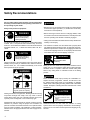
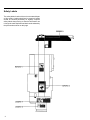
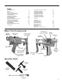
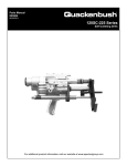
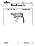
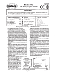
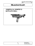
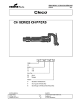
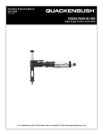
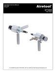
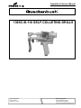
Operation & Service Manual
823005
2/01
136SC-B-118 SELF-COLLETING DRILLS
Houston Operation
7007 Pinemont
Houston, TX 77040
Recoules Operation
Zone industrielle - B.P. 28
Avenue Maurice Chevalier
77831 Ozoir-la-Ferriere Cedex France
1
Safety Recommendations
For your safety and the safety of others, read and understand
the safety recommendations and operating instructions before operating any drill motor.
Always wear protective equipment:
!
WARNING
Impact resistant eye protection
must be worn while operating
or working near this tool.
For additional information on eye protection, read the latest edition
of ANSI Z87.1, Occupational and Educational Eye and Face
Protection. This standard is available from the American National
Standards Institute, Inc., 11 West 42nd Street, New York, N.Y.
10036.
!
CAUTION
!
CAUTION
• Before the tool is connected to the air supply, the throttle should
be checked for proper operation (i.e., throttle valve moves freely
and returns to closed position).
• Before removing a tool from service or changing drill bits, make
sure the air line is shut off and drained of air. This will prevent the
tool from operating if the throttle is accidently engaged.
• Cutting tools used with these drill motors are sharp. Handle them
carefully to avoid injury.
• The collet and mandrel must be inserted into a properly sized
pre-drilled hole before starting the tool. An improperly sized predrilled hole prevents the mandrel from engaging the collet and
could result in slippage of the tool. An improperly selected collet
and mandrel can also result in slippage of the tool.
!
Personal hearing protection is
recommended when operating
or working near this tool.
Hearing protection is recommended in high noise areas (above
85dBA). Close proximity of additional tools, reflective surfaces,
process noises, etc., can contribute substantially to the sound
level experienced by the operator.
!
WARNING
WARNING
Wear respirator where
necessary.
Drilling or other use of this tool may produce hazardous fumes
and/or dust. To avoid adverse health effects utilize adequate
ventilation and/or a respirator. Read the material safety data
sheet of any cutting fluids or materials involved in the drilling
process.
!
CAUTION
Some non-ferrous metal chips (or dusts) are combustible. Examples: Aluminum, magnesium, Titanium, and Zirconium. See
the material safety data sheets for combustibility of materials
drilled. Never collect spark generating material with combustible
material. Examples: Collecting both steel and aluminum or steel
and titanium.
Do not wear loose fitting clothes,
long hair, gloves, ties or jewelry.
!
Follow good machine shop practices. Rotating shafts and moving
components entangle and entrap, and may result in serious
injuries. Never wear long hair, loose-fitting clothes, gloves, ties,
or jewelry when working with or near a drill of any type.
Quackenbush drills are designed to operate on 90psig (6.2 bar)
maximum air pressure using the proper hose. Excessive air
pressure increases the loads and stresses on tool parts and drills,
and may result in breakage. The installation of a filter-regulatorlubricator in the air supply line ahead of the tool is highly recommended.
2
CAUTION
Slip and fall hazard.
Lubricant and coolant systems must
be properly maintained to avoid
leakage.
Hoses must be organized and care
taken to avoid tripping.
Quackenbush drills are often used with lubricant or cooling
systems which must be properly maintained to avoid leakage.
Failure to do so can result in serious injuries from slipping on oily
surfaces.
Safety Recommendations
!
WARNING
Pinch Hazard. Clamping and feed
mechanism can move when the air
supply is connected or disconnected.
Disconnect air supply before servicing.
To avoid injury, keep fingers and hands
away from the clamping and feed
mechanism areas.
Due to the number and variety of tooling applications, the user's
methods engineering departments, ect., must consider any hazards that may be associated with each specific application of this
product and provide adequate operator protection from inadvertent contact with any moving components. The clamping and feed
mechanisms of self-colleting drill motors are exposed for visibility
and can move when the air supply is connected or disconnected.
To avoid injury, keep fingers and hands away from these areas
when handling or operating this tool.
Any tool operator should be aware of the following warning signs
and symptoms so that a problem can be addressed before it
becomes a debilitating injury. Any user suffering from prolonged
symptoms of tingling, numbness, blanching of fingers, clumsiness or weakened grip, inability to hold objects, nocturnal pain in
the hand, or any other disorder of the shoulders, arms, wrists, or
fingers should notify their employer so that a review of what steps
might be taken to prevent further occurances. These steps might
include but are not limited to, repositioning the workpiece or
redesigning the workstation, reassigning tool users to other jobs,
rotating jobs, changing worker pace, and/or changing the type of
tool used so as to minimize stress on the operator. Some tasks
may require more than one type of tool to obtain the optimum
operator/ tool/ task relationship.
Avoid
Extension
!
Neutral
Avoid
Flexion
Avoid
Radial Deviation
OK
Avoid
Neutral
Ulnar Deviation
WARNING
Repetitive work motions can
injure your hands and arms.
!
OK
WARNING
Exposure to vibration can
injure your hands and arms.
Some individuals are susceptible to disorders of the hands and
arms when exposed to vibration and/or tasks which involve
repetitive work motions. Those individuals predisposed to vasculatory or circulatory problems may be particularly susceptible.
Cumulative trauma disorders such as carpal tunnel syndrome and
tendinitis can be caused or aggravated by repetitious, forceful
exertions of the hands and arms. These disorders develop gradually over periods of weeks, months, and years. Tasks should be
performed in such a manner that the wrists are maintained in a
neutral position, which is not flexed, hyperextended, or turned side
to side. Stressful postures should be avoided and can be controlled through tool selection and work location.
The following recommendations will help reduce or moderate the
effects of repetitive work motions. The operator of any drill should:
• Use a minimum hand grip force consistent with proper control
and safe operation
• Keep body and hands warm and dry
• Avoid anything that inhibits blood circulation
— Smoking Tobacco
— Cold Temperatures
— Certain Drugs
• Avoid awkward postures
• Keep wrists as straight as possible
• Interrupt work, activities, or rotate jobs to provide periods free
from repetitive work motions.
3
Safety Labels
The safety labels found on this tool are an essential part
of this product. Labels should not be removed. Labels
should be checked periodically for legibility. Replace
safety labels when missing or when the information can
no longer be read. Replacement labels can be ordered by
the part numbers shown on this page.
4
Index
2-3
4
5
5
6
7-10
11
12
14-15
15-18
18
19
20
21
22
23
24
25
25
Safety Recommendations
Safety Labels
Index
Major Tool Components
Introduction and General Information
Air and Hydraulic System Diagrams
Backhead Disassembly
Spindle Adjustment Disassembly
Quill and Pressure Foot Removal
Feed Clamp Disassembly
Dwell Valve Disassembly
Disassembly of Feed Rate Adjustment Valve
Unclamp Check Valve Disassembly
Retract and Dwell Valve Disassembly
Hydraulic Fluid Reservoir Disassembly
Trigger Disassembly
Pilot Valve Disassembly
Filling and Bleeding the Hydraulic System
Tool Adjustments
Accessories
Depth Control
Cover
Bypass Cover
Template Boss
(See Chart)
Trigger
Variable Spacing
Pressure Foot
Air Inlet Bushing
(3/8-18 FNPT)
34
34
34
35
35-38
39
40
41
42
43
Template Boss
Jig Collet Foot Attachment
High Curvature Pad
Booster Pump Assembly
Mist Lubricator Assembly
Trouble Shooting
NDSJC Jig Collet Foot Kit
DSJC Jig Collet Foot Kit
Maintance Kit
Piping Layout for Compressed Air Lines
Major Tool Components
Spindle
Adjustment
26-31
32
32
32
32
32
33
33
33
136SC-B Q-Matic Drill Assy and Parts List
400 RPM Gear Set Assembly
950 RPM Gear Set Assembly
2100 RPM Gear Set Assembly
3100 RPM Gear Set Assembly
6000 RPM Gear Set Assembly
7800 RPM Gear Set Assembly
11500 RPM Gear Set Assembly
22500 RPM Gear Set Assembly
Accessory Air
Port (1/8-27 NPT)
Motor
Exhaust
Backhead
Dwell
Adjustment
Hydraulic
Fluid Fitting
Adjustable Tail
Pad
Spindle
Adjustment
Clamp
Feed Sleeve
Trigger Lock
Specials Tools
5
Introduction and General Information
The 136SC-B-118 is an air operated, hydraulically controlled tool
that automatically clamps to the material, drills and countersinks
close tolerance holes in one operation. This drill will produce high
quality holes in aluminum, steel, titanium and petroleum hybrid
materials primarily found in the aircraft/aerospace industries.
This drill motor has been designed using state-of-the-art technology that provides maximum power, minimum weight and the
highest degree of accuracy for demanding hole preparation
requirements.
Technical Data
Feed Stroke: Feed stroke of the 136SC-B-118 is 1.18 inches to
drill and countersink in 1 inch stacked material. The feed stroke
is unaffected by the collet stroke.
Collet Stroke: The 136SC-B-118 will clamp throughout its .56
inch stroke. Collet stroke is unaffected by feed stroke. Spindle
Adjustment: The spindle adjustment of .312 inch allows for drill
length variations. See Spindle Adjustment information.
Countersink Depth Control: A micrometer adjustment provides
for countersink stop repeatability within .001 inch.
Cutter Sizes: The 136SC-B-118 will accommodate .312 diameter drills without countersink and .250 diameter drills with .505
countersink diameter.
Feed Rate: An adjustable drill feed rate mechanism enables the
136SC-B-118 to drill from 5 seconds per inch to 1 minute per inch.
See Feed Rate Adjustment information.
Cutter to Collet Spacing: The cutter to collet distance is adjustable between .500 inch minimum to 2.75 inch maximum.
Coolant: The 136SC-B-118 has a drill point coolant port in the
pressure foot. A coolant mist lubricator is available (See Accessories).
136SC-B-118 DRILL MOTOR SPECIFICIATIONS
Air Motor: The air motor develops .88 horsepower when supplied with air at 90 p.s.i.
Air Consumption: Air consumption of the 136SC-B-118 is 35
c.f.m. at 90 p.s.i. dynamic.
Weight: Tool weight with the steel pressure foot is 7.0 pounds.
Spindle Speeds: Eight geared spindle speeds are available:
400, 950, 2100, 3100, 6000, 7800,11500, and 22500 RPM. Any
gear set can be used with the 136SC-B-118 tool.
Trigger Lock: A trigger lock is provided which allows the tool to
be locked in the “Operate” position. With the lock activated, the
tool will run through the clamp, feed and retract cycles, but it will
not unclamp or stop the motor until the trigger lock is manually
released.
Tool Start-Up
The 136SC-B-118 drill is shipped from the factory equipped to the
customer’s specifications: spindle RPM, spindle to accommodate
cutter type desired, pressure foot type, collet guide to accommodate collet desired and optional booster pump (if required).
After unpacking, examine the customer-specified equipment on
this tool to verify type and speed of components.
Attach air line to 3/8-18 NPT inlet bushing. If quick disconnect
fittings are used, 3/8 in. ID are minimum. The 136SC-B-118 drill
requires a supply of clean 90-100 PSI air. Air consumption is 35
CFM at 90 PSI. The use of the in-line lubricator will provide the
proper lubrication for the air motor and will significantly increase
the tool life expectancy. Because O-rings are extensively used to
seal systems within the tool, the elimination of foreign particles
and other contaminants will reduce the possibility of damage to
these parts. Always inspect O-rings for damage or wear and
replace as required. The use of silicone O-ring lubricant is strongly
recommended during reassembly. The addition of oil in the air line
will also increase motor and valve life as well as the life of the
O-rings.
WEIGHT
7.0 LBS. MAX. W/ALUMINUM FOOT
AIR CONSUMPTION
35 C.F.M. @ 90 P.S.I. DYNAMIC
HORSE POWER
APPROX. .88 @ 90 P.S.I.
O/A LENGTH
10.12 IN. MAX WITH SPINDLE ADJUST AT FULL EXTENSION
STROKE
1.18 IN. (DRILL & C/SINK 1 IN. STACK)
COLLET STROKE
.56 IN. (NO LOSS OF FEED STROKE)
COUNTERSINK
COUNTERSINK STOP REPEATS WITHIN .001 IN.
FEED RATE
MIN. 5 SEC. PER INCH, MAX 1 MIN. PER INCH
SPINDLE SPEEDS
400, 950, 2100, 3100, 6000, 7800, 11,500 & 22,500 RPM
DRILLING THRUST
130 LBS. MAX. (UNREGULATED AIR)
CLAMP FORCE
230 LBS. START CLAMP FORCE (UNREGULATED AIR)
SPINDLE ADJUSTMENT
.312 IN. ADJUSTMENT TO ALLOW FOR DRILL LENGTH
VARIATIONS
MAX. DRILL SIZES
.312 (NO C/SINK), .250(.505 C/SINK DIA.)
COLLET FOOT SPACING
.500 IN. MIN.-2.75 IN. MAX.
SPINDLE
.375 IN. DIA. W/1/4-28 THR'D FOR I.D.
THREAD TYPE DRILLS OR 1/4-28 MALE THD. DRILLS
COOLANT
AIR BLAST PORT & DRILL POINT PORT IN TEMPLATE STD.,
COOLANT MIST LUBRICATOR AVAILABLE.
6
7
8
9
10
11
12
13
14
15
16
17
18
19
20
21
22
23
24
Filling & Bleeding the
Hydraulic System
WARNING: Disconnect air-supply before servicing.
Clamp mechanism moves when connecting or removing air supply.
Keep hands and fingers away from clamping and feed mechanism.
The 136-118 drill hydraulic system will periodically require
filling and/or bleeding. If the oil level indicator is near the "Add
Fluid" mark, replenish the system using Mobil D.T.E. light or
equivalent hydraulic fluid.
FILLING
Connect the hydraulic fluid source to the tool using filler
fitting number 622871 or the new 624235/624942 filler
assembly. The fluid supply pressure should be 100-150
P.S.I. so the tool's internal check valve can be opened. Start
the hydraulic fluid source and fill the tool until the oil level
indicator shows full. Bleeding the tool should not be necessary if air has not been introduced into the system. Disconnect the tool from the fluid source and return to service.
fluid circulating though the tool, depress the trigger and cycle the tool
several times to remove any air from within the tool. Visually check
the clear return line for any air bubbles. When no bubbles are seen
disconnect the air supply. Turn off the hydraulic supply and remove
the filler fitting and return stem from the tool. Reinstall the .125
diameter steel ball and 10-32 set screw into the bleed port and
tighten. Test the tool for proper feed control before returning to
service.
BLEEDING
Remove the 10-32 set screw and the .125 diameter steel
ball from the bleed port. This bleed port is located on the
lower left hand side of the main housing (see section C-C
items 59 and 101 for more detail). Open feed control valve
to the fastest setting. This allows the fluid to flow unrestricted. Set the depth stop to the longest stroke. This must
be done to completely bleed the air from the hydraulic fluid.
Attach the filler fitting 622871 or the new 624235/624942
filler assembly to the hydraulic fill fitting. Thread the return
stem part number 624235 into the 10-32 bleed port and
hand tighten. Attach air line to tool and turn on air supply.
Turn on hydraulic pump to circulate fluid. With the hydraulic
Tool Adjustments
WARNING: Disconnect air-supply before servicing. Clamp
mechanism moves when connecting or removing air supply.
Keep hands and fingers away from clamping and feed
mechanism.
Spindle Stroke Adjustment
Loosen spindle adjustment lock, then turn spindle adjustment knob. Right hand rotation advances cutter forward; left
hand rotation returns cutter. Correct cutter point position is
flush with face of template boss. When cutter is properly
adjusted, lightly tighten spindle adjustment lock to hold
adjustment.
Micrometer Depth Adjustment
Loosen set screws, and rotate depth adjustment nut.
Clockwise rotation increases depth; counterclockwise decreases depth. Graduations scribed on barrel are in .001"
increments. When proper depth is achieved, lightly tighten
set screws.
Feed Rate Adjustment
With appropriate tool, turning feed rate adjustment counterclockwise, increases feed rate. Turning the screw clockwise
decreases feed rate. Feed rate can be measured by using
the following formula:
60 seconds
Time =
Feed Rate x Spindle Speed (rpm)
Dwell Adjustment
Insert appropriate size hex wrench into dwell adjustment
valve opening. Rotate wrench clockwise until valve seats
lightly. Rotate valve counterclockwise 1/4 turn to obtain base
setting.
Note: If adjustment valve is opened too far, drill motor will not
cycle, and feed cycle cannot be obtained. To correct, turn
valve clockwise to seat valve and set according to instructions above.
If valve is closed too far, retract cycle cannot be obtained. To
correct, turn valve counterclockwise and set according to
instructions.
Closing valve increases countersink dwell time; opening
valve decreases countersink dwell time.
Tail Pad Adjustment
The purpose of the tail pad is to compensate for slight
surface curvature of the workpiece being drilled and to
assure that the hole being drilled is perpendicular to the
surface.
To adjust to a flat plane for drilling flat surfaces, use a straight
edge between the tail pad and face of template boss and
adjust the tail pad until the straight edge is flush with the
face of the template boss.
An optional tail pad is available for high curvature sur faces.
(See Accessories for additional information.)
25
26
Old 625646 - 6-32
New 622354 - 8-32
27
28
29
30
31
400 RPM GEAR SET ASS'Y
(621646 REF.)
950 RPM GEAR SET ASS'Y
(621647 REF.)
93
93
108
115
122
116
116
122
122
85
148
146
85
144
123
147 144 123
81
623538
869254
623572
812231
622134
623507
623536
623535
623504
847095
CODE
NO.
148
1
3
147
3
145
1
144
123
2
2
122
1
116
1
115
93
1
1
85
81
1
ITEM Q'TY
NO. REQ'D
WASHER,FLAT
GEAR,IDLER,1-ST RED.
BEARING
RING,RETAINING
KEY,WOODRUFF
CARRIER,PLANET
GEAR,INTERNAL
GEAR,SPINDLE
GEAR,REDUCTION
BEARING,BALL
DESCRIPTION
2100 RPM GEAR SET ASS'Y
(621648 REF.)
GEAR,PINION
WASHER,FLAT
GEAR,IDLER,1-ST RED.
BEARING
RING,RETAINING
KEY,WOODRUFF
CARRIER,PLANET
GEAR,INTERNAL
GEAR,SPINDLE
GEAR,REDUCTION
BEARING,BALL
DESCRIPTION
99
115
122
116
116
122
122
148
148
88
88
147 144 123
57
122
147 144 123 124
81
145
145
148
1
147
3
3
145
144
1
123
2
122
3
116
1
115
1
98
1
1
88
1
81
1
57
ITEM Q'TY
NO. REQ'D
32
869645
623538
869637
623572
812231
622134
623506
623537
623535
623504
847095
CODE
NO.
3100 RPM GEAR SET ASS'Y
(621649 REF.)
98
115
81
145
147
147
3
3
146
1
144
2
123
2
122
1
116
1
108
1
93
85
1
81
1
ITEM Q'TY
NO. REQ'D
122
869645
623538
869637
623572
812231
622134
623506
623537
623534
623505
847095
623529
CODE
NO.
GEAR,PINION
WASHER,FLAT
GEAR,IDLER,1-ST RED.
BEARING
RING,RETAINING
KEY,WOODRUFF
CARRIER,PLANET
GEAR,INTERNAL
GEAR,SPINDLE
SHAFT,GEAR
BEARING,BALL
GEAR,REDUCTION
DESCRIPTION
148
1
3
147
3
145
144
1
124
1
123
2
122
3
1
116
115
1
99
1
88
1
81
1
ITEM Q'TY
NO. REQ'D
869645
623538
869637
623572
623530
812231
622134
623506
623537
623533
623505
847095
CODE
NO.
GEAR,PINION
WASHER,FLAT
GEAR,IDLER,1-ST RED.
BEARING
GEAR,REDUCTION
RING,RETAINING
KEY,WOODRUFF
CARRIER,PLANET
GEAR,INTERNAL
GEAR,SPINDLE
SHAFT,GEAR
BEARING,BALL
DESCRIPTION
81
7800 RPM GEAR SET ASS'Y
(621651 REF.)
6000 RPM GEAR SET ASS'Y
(621650 REF.)
104
115
122
116
98
122
122
148
143
88
147 144 123 125
145
1
148
3
147
145
3
144
1
1
125
123
2
122
3
1
116
1
115
1
104
1
88
1
81
ITEM Q'TY
NO. REQ'D
869645
623538
869637
623572
623531
812231
622134
623506
623537
623532
623505
847095
CODE
NO.
81
GEAR,PINION
WASHER,FLAT
GEAR,IDLER,1-ST RED.
BEARING
GEAR,REDUCTION
RING,RETAINER
KEY,WOODRUFF
CARRIER,PLANET
GEAR,INTERNAL
GEAR,SPINDLE
SHAFT,GEAR
BEARING,BALL
57
143
1
2
123
2
122
1
98
81
1
1
57
ITEM Q'TY
NO. REQ'D
DESCRIPTION
99
104
122
122
143
143
143
1
1
124
2
123
2
122
1
99
1
81
ITEM Q'TY
NO. REQ'D
623612
623530
812231
622134
623533
847095
CODE
NO.
SHAFT,GEAR
GEAR,REDUCTION
RING,RETAINING
KEY,WOODRUFF
GEAR,SPINDLE
BEARING,BALL
DESCRIPTION
81
SHAFT,GEAR
RING,RETAINING
KEY,WOODRUFF
GEAR,SPINDLE
BEARING,BALL
GEAR,REDUCTION
DESCRIPTION
22500 RPM GEAR SET ASS'Y
(621653 REF.)
11500 RPM GEAR SET ASS'Y
(621652 REF.)
124 123
623612
812231
622134
623534
847095
623529
CODE
NO.
123
125 123
81
143
1
1
125
2
123
2
122
1
104
1
81
ITEM Q'TY
NO. REQ'D
623612
623531
812231
622134
623532
847095
CODE
NO.
81
SHAFT,GEAR
GEAR,REDUCTION
RING,RETAINING
KEY,WOODRUFF
GEAR,SPINDLE
BEARING,BALL
DESCRIPTION
33
Accessories
Template Boss
APPLICATION
B
A
TEMPLATE
CUTTER
HOLE DIA.
DIA.
.434
.271
.434
.286
.434
.317
.497
.271
.497
.286
.497
.317
.497
.349
.497
.380
.622
.317
.622
.349
.622
.380
.622
.411
.622
.489
.622
.505
Jig Collet Foot Attachments
Depth Sensing Jig ColIet Foot (Pictured)
Depth sensing jig collet foot is used for accurately drilling and
countersinking hole layouts utilizing a simple fixture plate. The
cutter passes centrally through the drillmotor collet to produce
holes concentric with the fixture plate holes. The depth sensing sleeve will drill and accurately countersink with fixture-toworkpiece variations of up to .125". Coolant and air blast port
is fitted to the foot.
User must specify template hole and drill-countersink size as
well as drill-countersink configuration.
Non Depth Sensing Jig Collet Foot
Non-depth sensing jig collet foot is similar to the above foot
without depth sensing capability. This foot is used for straight
drilling applications where “rough” depth sensing only is required. This foot grips straight shank drills utilizing an “O-W”
type collet (not supplied).
User must specify template hole and drill size.
34
TEMPLATE BOSS
CODE
NO.
623573
623574
623575
623576
623577
623578
623579
623580
623581
623582
623583
623584
623585
623586
High Curvature Pad Assembly
A high curvature pad (Part No.621522) is available for use in
place of the standard pressure foot pad. The high curvature
pad enables the drill to be used on surfaces with a greater
curvature than the standard pad is capable of handling.
Accessories
Booster Pump Assembly
11
REF .88 FREE LG.
5
4
1
14
12
21
2
6
3
20
12
10
REF .34 FREE LG.
8
7
9
12
13
18
SEE NOTE 1
SEE NOTE 1
NOTES:
18
1. ITEMS 17, 19 & 21 TO BE SUPPLIED LOOSE
WITH BOOSTER PUMP ASSEMBLY.
SEE NOTE 1
ITEM
NO.
NO.
REQ'D.
1
1
621500
ASSY, BODY
2
1
621501
ASSY, END PLATE (HIGH PRESS.)
3
1
622660
END PLATE (LOW PRESS.)
4
1
622792
GASKET, END PLATE
5
1
622662
VALVE, PRESS. RELIEF
6
1
622663
PISTON, PRESS. RELIEF
7
2
622664
VALVE, CHECK
8
1
622665
VALVE, SHUTTLE
9
1
622666
PISTON
10
1
622652
SPRING, COMPRESSION
11
1
622653
SPRING, COMPRESSION
12
3
844304
O-RING
13
1
625112
GASKET
14
2
622654
O-RING
15
1
844308
O-RING
16
1
844315
O-RING
17
2
847710
O-RING
18
10
863337
SCREW
19
3
617245
SCREW
20
1
622845
RETAINER RING
21
3
844303
O-RING
CODE
NUMBER
DESCRIPTION
NOTE: EXAMINE THESE SURFACES FOR BURRS
SCRATCHES, ETC. PRIOR TO ASSEMBLY.
SURFACES MUST BE FLAT & SMOOTH FOR PRORER SEALING
For increased clamping force or feed pressure, an optional Booster Pump (621482) is available. The pump provides extra
clamp and feed pressures when drilling Titanium or taper drilling applications. The Booster Pump assembly will increase
both clamp and feed forces by a factor of 2.5. The pump is easily installed on the Q-Matic Drill by replacing the cover supplied
with the tool with the Booster Pump using the three screws supplied with the pump.
Mist Lubricator Assembly
The mist lubricator assemblies are available to introduce coolant and an air blast to the cutter. The lubricator is actuated
by air from the accessory air tap on the motor side and only functions when the motor is running. The following three pages
show the three different types available. The mist lubricators and mounting brackets can be purchased as complete
subassemblies using these numbers: Manual fill small capacity - 631878, Pressure fill small capacity - 631879, Pressure
fill large capacity - 631880. The reservoirs and individual parts can be ordered using numbers listed on drawings.
35
36
x
x
Upper number is item.
Lower number is quantity required.
PRESSURE FILL MIST LUBRICATOR
Note:
x
x
Upper number is item.
Lower number is quantity required.
MANUAL FILL MIST LUBRICATOR
Note:
37
38
Note:
x
x
Upper number is item.
Lower number is quantity required.
136SC-B-118 MIST LUBRICATOR MOUNTING
MIST LUBRICATORS & MOUNTS COMPLETE SUBASSEMBLIES:
MFSC - 631878, PFSC - 631879, PFLC - 631880.
TROUBLE SHOOTING
SYMPTOM
Air motor and/or clamp and feed functions do not start when trigger is depressed.
REASON
Trigger or pilot valves clogged with foreign matter.
SOLUTION
Remove trigger and pilot valves (separately) and inspect for rust or debris. Inspect O-rings and replace if necessary.
Air motor does not run when trigger is
depressed, but feed and clamp functions
properly.
Gears damaged or jammed with debris.
With air line disconnected check for free
spindle rotation with hex key wrench in end
of spindle. Remove backhead, clean and
inspect gears for damage.
Foreign matter in motor inlet.
Remove motor and clean debris from motor inlet.
Broken rotor blades, rotor or gear bearings.
Remove motor and inspect rotor blades
and bearings. Replace if necessary.
Pilot valve or retract and dwell valve
sticky (not fully reset), or bad O-ring.
Remove and check valves for debris and
free movement of spool. Inspect O-rings,
lubricate and reassemble.
Leaking O-ring on air motor rear bearing support.
Remove and inspect O-rings. Replace if
necessary and reassemble.
Motor runs, but clamp & feed functions do
not start.
Unclamp check valve doesn’t shift when
trigger is depressed.
Remove unclamp check valve and inspect
for debris, free movement and damaged
O-rings. Lubricate and reassemble.
Motor runs, clamps but doesn’t feed.
Feed control valve “closed”
Back off feed control valve counterclockwise until feed commences.
Debris in the hydraulic system.
Remove bleed port and bleed hydraulic
system until fluid is clear.
Air in hydraulic system.
Back feed control valve two turns from
seat, and bleed as above.
Persistent air in hydraulic system.
Remove hydraulic reservoir piston and
check or replace O-rings.
Dwell valve seated too tightly.
Back dwell valve off from seat 1/8 turn to
1-1/2 turn.
Retract and dwell valve doesn’t shift.
Remove retract and dwell valve and inspect for debris, free movement and damaged O-rings. Lubricate and reassemble.
Depth control adjusted out of the max.
range of the tool.
Readjust depth control nut within the feed
stroke of the tool (ref.: 1.10 max. stroke).
Tool retracts shortly after trigger
depressed.
Dwell valve opened too far off of seat.
Turn dwell valve clockwise (should be 1/8
to 1-1/2 turns of seat).
Tool “pulses” on retract (rapid ‘’feed
retract-feed retract”).
Damaged O-rings on retract and dwell
valve.
Remove retract and dwell valve, inspect O-rings and replace as necessary.
Lubricate and reassemble.
Air motor “idles” when trigger valve is
released.
Lunge during feed or variation in feed
rate.
Tool doesn’t retract at end of feed stroke.
39
19
16
17
2
25
1
4
6
3
22
14
5
18
12
10
20
21
11
23
24
7
15
13
8
9
136SC-B-118 NON-DEPTH SENSING
JIG COLLET FOOT KIT FOR .500631400, .625-631401, .750-631402 &
.875-631403
40
ITEM NO.
QTY.
CODE NO.
DESCRIPTION
1
1
1
1
2
1
1
1
1
1
COLLET .500 STRAIGHT
COLLET .625 STRAIGHT
COLLET .750 STRAIGHT
COLLET .875 STRAIGHT
MANDREL ASSEMBLY
3
3
3
3
4
4
4
4
5
5
5
5
6
6
6
6
6
6
6
6
7
8
9
10
11
12
13
14
15
16
17
18
19
1
1
1
1
1
1
1
1
1
1
1
1
1
1
1
1
1
1
1
1
1
1
1
1
1
1
1
4
1
1
1
8
1
20
21
22
23
24
25
1
1
1
1
1
1
624568
624569
623436
623437
Specified by
Customer
625357
625390
625358
623452
625963
625964
625965
625966
625159
625160
625161
625162
625176
625177
625178
625179
625180
625181
625182
625183
627033
621645
627032
832128
624531
627035
624533
622774
844308
623223
624905
622063
Specified by
Customer
863888
627030
627031
627029
627028
622922
COLLET SPRING .500
COLLET SPRING .625
COLLET SPRING .750
COLLET SPRING .875
LIFT FINGER .500
LIFT FINGER .625
LIFT FINGER .750
LIFT FINGER .875
HEX NUT .500
HEX NUT .625
HEX NUT .750
HEX NUT .875
.500 - NOSE. .375 - .500 GRIP RANGE
.500 - NOSE, .625 - 1.000 GRIP RANGE
.625 - NOSE. .375 - .500 GRIP RANGE
.625 - NOSE, .625 - 1.000 GRIP RANGE
.750 - NOSE. .375 - .500 GRIP RANGE
.750 - NOSE, .625 - 1.000 GRIP RANGE
.875 - NOSE. .375 - .500 GRIP RANGE
.875 - NOSE, .625 - 1.000 GRIP RANGE
FOOT BODY
QUILL ASSEMBLY
SPINDLE
DOWEL PIN
PRESSURE FOOT NUT
PULL ROD
FEED SLEEVE
SCREW. SOCKET HEAD
"O"-RING
PLUG
HOSE FITTING WITH GASKET
SCREW. BUTTON HEAD
ERICKSON COLLET
COLLET CHUCK
HAND GUARD
HAND GUARD
CUP RETAINER
RETAINER RING
HEX NUT
24
25
6.320
19
17
18
16
2.080 TO HANDLE (REFERENCE)
10
9
22
23
DIA.
14
.3752
.3747
1/4-28INT. THREAD
8
7
13
6
15
21
2.480
11
.500
.750 STANDOFF
TYP. CUTTER CONFIGURATION
12
DRILL JIG
.125 SENSING RANGE
WORK PIECE
MANDREL
COLLET
NOSE
COMPRESSION SPRING
YOKE
HEX NUT
SENSING SLEEVE ASS'Y.
FOOT BODY
QUILL ASSEMBLY
SPINDLE
HEX NUT
LIFT FINGER
DOWEL PIN
NUT
PULL ROD
FEED SLEEVE
SOCKET HEAD CAP SCREW
SPRING BLOCK
DOWEL PIN
YOKE PIN
BUTTON HEAD CAP SCREW
BUTTON HEAD CAP SCREW
EXTENSION SPRING
20
623431
623436
625747
622872
623448
623441
631327
624663
621303
624918
622922
624553
832128
624556
624554
624555
863337
624673
843280
623274
622053
622063
622873
5
1
1
1
1
1
1
1
1
1
1
1
1
1
1
1
1
1
1
1
2
4
4
2
136SC-B-118 DEPTH SENSING
JIG COLLET FOOT KIT FOR .750- 631325
4
1
2
3
4
5
6
7
8
9
10
11
12
13
14
15
16
17
18
19
20
21
22
23
DESCRIPTION
3
CODE NO.
2
QTY.
1
ITEM NO.
41
MAINTENANCE KIT - 621953
PART NO.
42
NAME OF PART
QTY.
382370
TOOL BOX
1
622849
ASSEMBLY TOOL
1
623014
ASSEMBLY TOOL, PRESS. FOOT NUT
1
623015
ASSEMBLY TOOL, TRIGGER LOCK
1
623334
ASSEMBLY TOOL, PRESSURE HYDRAULIC & FRONT ENCLOSURE
1
623515
ASSEMBLY TOOL, PRESSURE FOOT NUT
1
623520
ASSEMBLY TOOL, BULKHEAD REMOVAL
1
623647
ASSEMBLY TOOL, DEPTH STOP
1
632424
REMOVAL TOOL, VALVE
1
624759
SLIDE HAMMER PULLER
1
624760
ASSEMBLY FIXTURE
1
624761
WRENCH, SPINDLE BEARING LOCKNUT
1
624762
BEARING INSTALLER
1
624763
REMOVAL TOOL, FEED CONTROL VALVE
1
624764
REMOVAL TOOL, PILOT VALVE
1
624765
ARBOR PRESS FIXTURE
1
624766
VALVE INSTALLATION TOOL
1
624767
WRENCH, FEED CONTROL VALVE
1
624768
TEE WRENCH, FOOT BODY
1
NOTES
43
CooperTools
7007 Pinemont
Houston, Texas 77040
Phone: (713) 462-4521
Fax: (713) 460-7008
www.cooperindustries.com
44