1
Operating Instructions
Included Installation Instructions
Ceiling Mount Bracket
Model No.
WV-Q174B
Before attempting to connect or install this product,
please read these instructions carefully and save this manual for future use.
The model number is abbreviated in some descriptions in this manual.
Contents
Features.......................................................................................................................................... 3
Precautions.................................................................................................................................... 3
Precautions for installation............................................................................................................. 4
Major Operating Controls............................................................................................................... 6
Installations.................................................................................................................................... 7
Specifications............................................................................................................................... 11
Standard accessories................................................................................................................... 11
2
Features
This ceiling mount bracket is exclusively
designed to mount the camera, on a ceiling.
Refer to the catalog or operating instructions of
the camera for further information about the
compatible models.
This bracket can be used for an area with weak
pull-out strength such as plasterboard in a
double ceiling.
This bracket is an embedded type to reduce
the exposed portion of the camera body.
Precautions
Refer installation work to the dealer.
Installation work requires technique and experiences.
Failure to observe this may cause fire, electric
shock, injury, or damage to the product.
Be sure to consult the dealer.
Avoid installing this bracket in the locations where salt damage occurs or corrosive gas is produced.
Otherwise, the mounting portions will deteriorate and accidents such as a fall of this product
may occur.
The screws and bolts must be tightened to
the specified torque.
Loosening of mounting screws or bolts may
cause a fall of the product resulting in injury or
accidents.
Do not use this bracket except with suitable cameras
Failure to observe this may cause a drop resulting in injury.
Select an installation area that can support the total weight.
Selecting an inappropriate installation surface
may cause this product to fall down or topple
over, resulting in injury or accidents.
Installation work shall be started after sufficient
reinforcement.
Periodic inspections shall be conducted.
Rust on the metal parts or screws may cause a
fall of the product resulting in injury or accidents.
Consult the dealer for the inspections.
The exclusively designed mount bracket
shall be used.
Failure to observe this may cause a drop resulting in injury or accidents.
Use the exclusively designed mount bracket for
installation.
Do not install this product in locations
subject to vibration.
Loosening of mounting screws or bolts may
cause a fall of the product resulting in injury or
accidents.
Do not strike or give a strong shock to this
product.
Failure to observe this may cause fire or injury.
Install this product in a location high
enough to avoid people and objects from
bumping the product.
Failure to observe this may cause injury.
Do not hang down from this product or
use this product as a pedestal.
Failure to observe this may cause a drop resulting in accidents.
Do not rub the edges of metal parts with
your hand.
Strong rubbing may cause injury.
3
Precautions for installation
Panasonic assumes no responsibility for injuries or property damage resulting from failures arising out of improper installation or operation inconsistent with this documentation.
The installation should comply with local electrical code.
This product is designed to be used indoors.
This product is not operable outdoors.
Do not expose this product to direct sunlight for hours and do not install the product near a heater
or an air conditioner.
Otherwise, it may cause deformation, discoloration and malfunction. Keep this product away from
water and moisture.
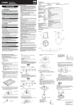
Installation area for this product
• Make sure that the installation area is strong enough to hold the total weight of the camera
assembly before installation.
• The installation area shall have 70 mm {2-3/4 inches} or more space behind the ceiling.
70 mm {2-3/4 inches} or
more
Ceiling board: between 9 mm {3/8 inches}
and 30 mm {1-3/16 inches}
• The thickness of the ceiling board for installation can range between 9 mm {3/8 inches} and
30 mm {1-3/16 inches}.
Do not place this product in the following places:
• Locations where it may get wet from rain or water splash (including under the eaves, etc.)
• Locations where a chemical agent is used such as a swimming pool
• Locations subject to moisture or oil smoke such as a kitchen
• Locations that have a specific environment that is subject to an inflammable atmosphere or solvents
• Locations where a radiation, an X-ray, a strong radio wave or a strong magnetic field is generated
• Locations where corrosive gas is produced, locations where it may be damaged by briny air such
as seashores
• Locations where the temperature is not within the specified range (–10 °C to +50 °C {14 °F to
131 °F})
• Locations subject to vibrations, such as on vehicles, marine vessels, or above product lines (This
product is not designed for on vehicle use.)
• Locations subject to condensation as the result of severe changes in temperature
4
Mounting method for this product
This product is designed to be used as a pendant mount camera. If the product is mounted on a
desktop or at a slant, it may not work correctly and its lifetime may be shortened.
Screw tightening
• The screws and bolts must be tightened with an appropriate tightening torque according to the
material and strength of the installation area.
• Do not use an impact driver. Use of an impact driver may damage the screws or cause tightening
excessively.
• When a screw is tightened, make the screw at a right angle to the surface. After tightening the
screws or bolts, perform checks to ensure that the tightening is sufficient enough so that there is
no movement or looseness.
Make sure to remove this product if it will no longer be used.
5
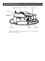
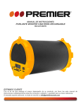
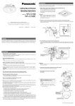
Major Operating Controls
Clamping screw Spring hook
Main body
Clamping screw
Clamp plate
Triangle mark
(top/ bottom)*
Decorative cover
Spring hook
Clamp plate
* Because the triangle mark is engraved on the bracket, it can be seen from
both the top and bottom sides.
6
Installations
Be sure to read "Precautions" (☞ page 3) and "Precautions for installation" (☞ page 4) before
installation. Read the Installation Guide for the camera to be installed as well.
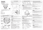
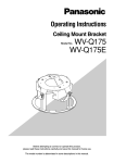
Step1
Make a hole of 160 mm {6-5/16 inches} diameter using a
specialized tool, etc.
Make a mounting hole in the ceiling using the
template (accessory).
Important:
• Make a hole precisely. When the opened
hole is bigger or deformed too much,
the ceiling mount bracket cannot be
stuck on the ceiling board securely.
Step2
m
0m
es}
ø16 6 inch
1
/
{6-5
Ceiling
Position 2 of the spring hooks of the main body as shown
in the illustration below.
When the ceiling mount bracket is installed after positioning them in the opposite side, they may
become hard to pull out.
Main body
←
Move the hook head downward.
Spring hook
7
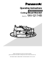
Step3
Fix the plates to the ceiling mount bracket.
Attach the adjustment plates (accessory) or attachment plate (camera accessory) to the ceiling
mount bracket first if they are needed for the attachment of the camera body.
<When securing the camera body
using 2 screws>
<When securing the camera body
using the attachment plate>
Main body
Main body
Triangle mark
Adjustment plates
(accessory)
Attachment plate
(camera accessory)
Fixing screws (accessory)
Recommended tightening torque:
1.6 N·m {1.18 lbf·ft}
Step4
Triangle mark
Fixing screws (accessory)
Recommended
tightening torque:
1.6 N·m {1.18 lbf·ft}
Fix the ceiling mount bracket onto the ceiling board.
Loosen the fixing screws by rotating them counterclockwise until the length between the clamp
plates becomes wider than the thickness of the ceiling board. Insert the ceiling mount bracket into
the ceiling board, and clamp and secure the ceiling board by rotating the fixing screws clockwise.
Important:
• When the ceiling board is
plasterboard, make sure that
no crack was made on the
ceiling board by clamping.
Triangle mark
Main body
Maximum thickness
of the ceiling board is
30 mm
{1-3/16 inches} for
installation.
Step5
* The "Panasonic" logo on
the camera and the
decorative cover should
be located on the side of
this triangle mark.
Clamp plates
Clamp
the
ceiling
board.
Fixing screws (accessory)
Recommended tightening torque:
1.6 N·m {1.18 lbf·ft}
Connect the cables to the camera.
Remove the enclosure from the camera body and connect the cables from above the ceiling board
first. Refer to the operating instructions of the camera for information about connection points and
how to make connections.
8
Step6
Fix the camera body to the ceiling mount bracket.
The triangle mark of the ceiling mount bracket and the direction marker ( TOP) of the camera body
should be located on the opposite sides.
<When using 4 mounting holes>
Fix the camera using 4 fixing screws
(accessory).
Main body
<When using the adjustment plates>
Fix the camera on the adjustment plates
(accessory) attached in step 3 using 2 fixing
screws (accessory).
Main body
Triangle mark
Triangle mark
* Install the camera so that
the wiring should be connected from the side of
the ceiling mount
Camera body
bracket.
Camera body
Direction marker
( TOP)
Direction marker
( TOP)
Fixing screws (accessory)
Recommended tightening torque:
1.6 N·m {1.18 lbf·ft}
Fixing screws (accessory)
Recommended tightening torque:
1.6 N·m {1.18 lbf·ft}
Triangle mark
<When using the attachment plate>
Align the attachment fixing screws on the
bottom side of the camera with the holes
of the attachment plate, and temporarily
attach the camera by rotating it about 15°
clockwise. Next, secure the camera with
the camera fixing screw.
(Recommended tightening torque:
0.78 N·m {0.58 lbf·ft})
Holes of the
attachment plate
(x4)
Direction marker (
TOP)
Camera fixing screw
Important:
• When using the adjustment plates, do not pass the cables through the hole of the main body.
When the wiring touches the edges of the main body, the cables may get damaged.
9
Step7
Adjust the angle of view of the camera and attach the
enclosure.
Adjust the pan, tilt, etc. of the camera, and then adjust the
angle of view. When the adjustment is completed, attach the
enclosure to the camera.
* Refer to the Installation Guide of each camera for information
about how to adjust the angle of view and how to attach and
fix the enclosure.
* If the AF (Auto Focus) button on the side of the camera body
must be pressed after attaching the enclosure, use the AF
button push tool (accessory).
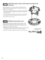
Step8
Attach the decorative cover.
Align the bracket with the 3 guides of the decorative cover,
pull out both the spring hooks and attach the hooks to the
decorative cover. Make sure that the cover is attached to the
ceiling with no space between them.
* There are 2 decorative covers. When using the attachment plate,
use the thick cover. Use the thin cover for other models.
* Match the "Panasonic" logos on the cover and on the camera.
10
The thickness of the
decorative cover
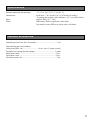
Specifications
Ambient operating temperature:
Dimensions:
Mass:
Finish:
–10 °C to +50 °C {14 °F to 131 °F}
ø186 mm × 76.2 mm(H*) {ø7-5/16 inches×3 inches}
*Including decorative cover thickness: 15.7 mm {5/8 inches}
Approx. 350 g {0.77 lbs}
Main body: Surface treatment steel sheet
Decorative cover: ABS resin (resin color: sail white)
Standard accessories
Operating Instructions (this document).........................................1 set
The following are for installation
Fixing screw (M4 x 8) ............................... 8 pcs. (incl. 2 spare screws)
Template (for tracing the hole shape) ....................................... 1 sheet
Adjustment plate .......................................................................2 pcs.
Decorative cover........................................................................2 pcs.
AF button push tool .....................................................................1 pc.
11
For U.S. and Canada:
For Europe and other countries:
Panasonic System Communications
Company of North America,
Unit of Panasonic Corporation
of North America
Panasonic Corporation
Two Riverfront Plaza, Newark, NJ 07102-5490
Panasonic Testing Centre
Panasonic Marketing Europe GmbH
Winsbergring 15, 22525 Hamburg, Germany
www.panasonic.com/business/
For customer support, call 1.800.528.6747
Panasonic Canada Inc.
http://panasonic.net
Importer's name and address to follow EU rules:
5770 Ambler Drive, Mississauga,
Ontario, L4W 2T3 Canada
(905)624-5010
www.panasonic.ca
© Panasonic System Networks Co., Ltd. 2014
Cs0314-0
PGQX1568ZA
Printed in China