1
Operating Instructions
Included Installation Instructions
Sun Shade
Model No.
WV-Q7118
Before attempting to connect or install this product,
please read these instructions carefully and save this manual for future use.
The model number is abbreviated in some descriptions in this manual.
Precautions
Refer installation work to the dealer.
Installation work requires technique and experience. Failure to observe this may cause fire, electric shock, injury, or damage to the product.
Be sure to consult the dealer.
The measures of protection against a fall of this product shall be taken.
Failure to observe this may cause a drop resulting in injury or accidents. Be sure to install the safety wire.
The screws and bolts must be tightened to the specified torque.
Failure to observe this may cause a drop resulting in injury or accidents.
Attaching procedures
Read the following descriptions together with the Installation Guide of the camera.
■ Attach to WV-SFV631L/WV-SFV611L series
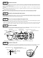
Step1
Procure the necessary parts
Procure the 5 fixing screws (M4: 4 for securing the bracket, 1 for securing the safety wire) used to mount the base
bracket (camera accessory). Next, loosen the screws on the left and right of the sunshade, and then remove the sunshade mount bracket.
● When the base bracket is mounted in Position E of Step 2 {3} of "Installation" in the Installation Guide of the camera,
procure 2 screws (M4, locally procured).
● Required pull-out capacity of a single screw/anchor bolt is 196 N {44 lbf} or more.
Step2
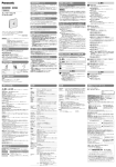
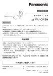
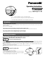
Prepare the safety wire
Attach the safety wire to the sunshade.
1 Pass the lopped end of the safety wire (accessory) through
the safety wire hole on the sunshade.
2 Pass the other end of the safety wire through the lopped
end passed through the safety wire hole.
Sunshade
Safety wire hole
Step3
Attach the brackets
Make 5 holes in the wall, insert the anchors, and then secure the sunshade mount bracket and the base bracket (camera accessory) together to the wall using 4 fixing screws (M4, locally procured) as illustrated in Step 6. (Minimum pull-out
strength: 196 N {44 lbf} (per 1 pc.))
● For information about attaching the base bracket, refer to Step 2 {3} of "Installation" in the Installation Guide of the
camera.
● Use installation template B (camera accessory) as a guide for the position of screws for the sunshade mount bracket
and base bracket (camera accessory).
● Position the hole for securing the safety wire so that there is no slack in the safety wire when it is attached.
● Beside the above 5 holes opened for the fixing screws, separate holes may have to be opened for wiring.
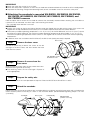
Step4
Attach the attachment plate and camera
Secure (recommended tightening torque: 0.78 N·m {0.58 lbf·ft}) the attachment plate (camera accessory) to the base
bracket (camera accessory) using 4 fixing screws (M4 x 8 mm, camera accessory), connect the wiring to the camera,
and then temporarily attach the camera to the attachment plate.
Step5
Secure the camera and adjust the angle of view
Remove the camera's enclosure, secure the camera with the camera fixing screw (recommended tightening torque:
0.78 N·m {0.58 lbf·ft}), adjust the angle of view, and then reattach the enclosure.
* Refer to the Installation Guide of the camera for more information about attaching the camera and adjusting the angle
of view as referred to in Step 4 and Step 5. Make sure to adjust the angle of view so that the sunshade is not visible.
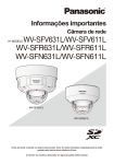
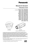
Step6
Attach the sunshade
Attach the sunshade to the top of the camera, and then secure the sunshade and sunshade mount bracket using the
screws on the left and right. (Recommended tightening torque: 0.78 N·m {0.58 lbf·ft})
Sunshade
Camera body
(with the enclosure attached)
Attachment plate
(camera accessory)
Sunshade mount bracket
Fixing screws for attachment plate (x4, camera accessory)
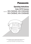
Step7
Base bracket (camera accessory)
Fixing screws (x4, locally procured)
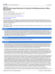
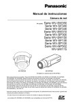
Attach the safety wire
Attach the safety wire attached to the sunshade to the foundation area of the architecture or where sufficient strength is
assured. Prepare the fixing screw according to the material of the area where the safety wire is to be installed.
Spring washer (accessory)
1 M4 screw (locally procured)
* Required pull-out capacity: 196 N {44 lbf}
Washer (accessory)
Safety wire
(accessory)
Wall
IMPORTANT:
● Attach the safety wire so that it has no slack.
● Attach the safety wire in a position so that if the sunshade were to become detached, it would not fall on nearby people.
● To prevent the mounting strength from becoming lower, do not use wooden screws to secure the safety wire.
■ Attaching the sunshade to mounted WV-SW559, WV-SW558, WV-SW355,
WV-SW352, WV-NW502S, WV-CW504F, WV-CW504S, WV-CW364S, and
WV-CW334S cameras
Here we explain how to attach the sunshade to cameras that are already mounted. When attaching the sunshade to a
camera that is not mounted, start from step 2 after mounting the camera.
* The sunshade mount bracket is not used.
IMPORTANT:
● Confirm that screws on the left and right of the base cover are aligned with the sides of the camera. If the screws are
aligned with the top and bottom of the camera, the sunshade cannot be attached in the correct direction.
● The maximum ambient operating temperature is +42 ºC {107.6 ºF} for the WV-NW502S, and +50 ºC {122 ºF} for the
WV-CW504F and WV-CW504S. The maximum ambient operating temperature for other models is +45 ºC {113 ºF}.
The minimum operating temperature of each camera is unchanged. Use the cameras within their minimum operating
temperatures.
● In order to attach the sunshade to the WV-CW504F, the WV-Q115A (locally procured) is required.
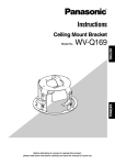
Step1
Base cover
Remove the base cover
Use the bit (accessory) to loosen the screws on the left
and right of the base cover, and then remove the base
cover from the camera.
Left and right screws
of the base cover
Step2
Enlargement of rear
view of the screw
Remove 2 screws from the
base cover
While pushing the screws from the rear, rotate them counterclockwise using the bit (accessory).
● The attaching screws are not used again. Dispose of
them appropriately.
Step3
Prepare the safety wire
Attach a safety wire in the same procedure in Step 2 of "Attach to WV-SFV631L/WV-SFV611L series".
Step4
Attach the sunshade
Rotate the screws on the left and right of the sunshade clockwise, and then secure the base cover and sunshade to the
mount bracket (camera accessory) as shown in the illustration below. (Recommended tightening torque: 0.78 N·m
{0.58 lbf·ft})
Sunshade
Base cover
Camera body
Mount bracket
(camera accessory)
Step5
Attach the safety wire
Make a hole for the safety wire in the foundation area of the architecture or where sufficient strength is assured, and
insert an anchor into the hole.
Secure the safety wire attached to the sunshade. Prepare the fixing screw according to the material of the area where
the safety wire is to be installed.
* The safety wire is attached with the same procedure in Step 7 of "Attach to WV-SFV631L/WV-SFV611L series".
Specifications
Ambient operating temperature:
Mass:
Dimensions:
Finish:
–45 °C to +50 °C {–49 °F to 122 °F}*
Approx. 540 g {1.19 lbs}
Diameter: 199 mm {7-13/16 inches}
Height: 162 mm {6-3/8 inches}
Light gray aluminum die cast
* When attaching the sunshade to WV-SW559, WV-SW558, WV-SW355, WV-SW352, WV-NW502S, WV-CW504F,
WV-CW504S, WV-CW364S, and WV-CW334S cameras, there are partial constraints on the ambient operating temperature.
Standard Accessories
Operating Instructions ...........................................................1 set
Sunshade mount bracket* .....................................................1 pc.
Safety wire.............................................................................1 pc.
Washer ..................................................................................1 pc.
Spring washer .......................................................................1 pc.
Bit (screw size 6.35 mm {1/4 inches} torx wrench) .................1 pc.
* The sunshade mount bracket is packaged with and attached to the sunshade.
For U.S. and Canada:
For Europe and other countries:
Panasonic System Communications
Company of North America,
Unit of Panasonic Corporation
of North America
http://panasonic.net
www.panasonic.com/business/
For customer support, call 1.800.528.6747
Two Riverfront Plaza, Newark,
NJ 07102-5490
Importer's name and address to follow EU rules:
Panasonic Testing Centre
Panasonic Marketing Europe GmbH
Winsbergring 15, 22525 Hamburg, Germany
Panasonic Canada Inc.
5770 Ambler Drive, Mississauga,
Ontario, L4W 2T3 Canada
(905)624-5010
www.panasonic.ca
© Panasonic System Networks Co., Ltd. 2014
PGQX1566ZA Cs0314-0
Printed in China