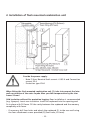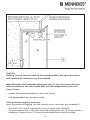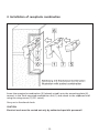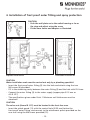
1
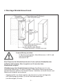
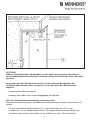
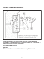
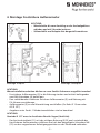
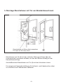
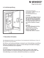
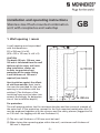
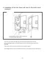
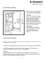
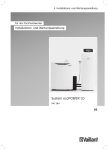
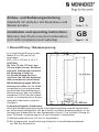
Einbau- und Bedienungsanleitung
Edelstahl UP-Verteiler mit Steckdosen und
Wasserarmatur
Installation and operating instructions
Stainless steel flush mounted combination
unit with receptacles and watertap
D
Seite 1 - 8
GB
Page 9 - 16
1. Maueröffnung / Wandaussparung
Es ist eine Maueröffnung mit den
Maßen 510 x 290 mm (H x B)
vorzusehen.
(470 x 250 x 120 mm; H x B x T)
ACHTUNG:
Die Tiefe (T) min. 120 mm, max.
140 mm ergibt sich aus der Wandstärke der Außenwand einschließlich Dämmung, Klinker etc.
Zur Gewährleistung der Frostsicherheit sind 150 mm Restwandstärke erforderlich (siehe Skizze).
Wärmedämmung gegen Kälteeinwirkung von außen: Für die Wandaussparung ist eine entsprechend
ausreichende Wärmedämmung in
Abstimmung mit dem Architekten
einzubauen! (Die Dicke der Dämmschicht ist entsprechend zur Bestimmung der Einbautiefe zu berücksichtigen!)
Zu berücksichtigender Brandschutz:
Durch die Wandaussparung wird die Feuerwiderstandsdauer und die Bauteilstärke
der Außenwand herabgesetzt. Mit dem Statiker und dem Brandschutzplaner ist ein
Konzept zum Brandschutz für den Wandeinbau-schrank (1) zu erstellen (Lösung für
eine F 90 Wand: Ummantelung mit 40 mm Promatect H verwenden).
(1) Mindestwandstärke von 150 mm ist einzuhalten!
(2) Bei Verlegung der Anschlussleitung Unterputz ist eine Mindestwandstärke
von 285 mm erforderlich!
-1-
2. Montage Wandeinbauschrank
Stromzuführung vorsehen:
-
FI-Absicherung beachten: Nennfehlerstrom ≤ 0,03 A und
Anschlussleitung 32 A
Schutzart IP 44
Beim Einpassen des Wandeinbauschranks (1) den späteren Wandaufbau der
Außenfassade beachten. Max. Ausgleich von 20 mm durch den
Blendrahmen möglich!
Kältedämmung ohne Brandschutzummantelung: Empfehlenswert ist eine
rückseitige Dämmung (z. B. durch Styropor). Rückseitige Dämmung einsetzen.
Schrank einsetzen und mit PU-Schaum fixieren. Hohlraum zwischen Schrank und
Mauerwerk komplett ausschäumen.
- Gegebenenfalls vier Löcher bohren und Schrank (1) mittels beiliegender
vier Befestigungsschrauben (2) an der Rückwand befestigen
(vier Bohrungen, Ø 8 mm).
-2-
ACHTUNG:
Erdung: Verbindung des Erdungskabels an der dafür vorgesehenen Schraube im
oberen Wandeinbauschrankbereich herstellen (sämtliche metallische Teile sind somit
geerdet).
Beim Einpassen des Wandeinbauschranks (1) den späteren Wandaufbau der
Außenfassade beachten. Max. Ausgleich von 20 mm durch den Blendrahmen
möglich!
- vorgestanztes Blech entfernen
- Bohrung von außen nach innen waagerecht vornehmen
Falls eine Brandschutzummantelung notwendig wird:
Brandschutzummantelung in die Mauerwerksaussparung einsetzen und Schrank (1)
setzen.
- Für die Frostsichere Außenarmatur (3) ist eine Bohrung von ≥ Ø 27 mm
erforderlich. Das im Wandeinbauschrank (1) vorgestanzte Loch dient dabei als
Schablone. Von innen nach außen ist ein Gefälle von max. 2% einzuhalten.
-3-
3. Einbau Steckdosenkombination
Steckdosenkombination (5) (anschlussfertig verdrahtet) auf Montageblech (6)
aufschrauben, im Wandeinbauschrank (1) anschließen und mit der Flügelschraube (7)
an der Schrankwand fixieren (20° schwenkbar).
Funktionsprüfung durchführen.
ACHTUNG:
Elektroarbeiten dürfen nur vom Elektro-Fachmann ausgeführt werden!
-4-
4. Montage Frostsichere Außenarmatur
ACHTUNG:
- Wandscheibe bis zum Anschlag an das Auslaufgehäuse
schieben und mit Schraube justieren
- Schlauchtülle und Adapter wie dargestellt montieren
Montage Aufputz
Montage Unterputz
ACHTUNG:
Wasserinstallationsarbeiten dürfen nur vom Sanitär-Fachmann ausgeführt werden!
- Frostsichere Außenarmatur (3) in die Bohrung stecken und mittels beiliegender
zwei M6-Schrauben (4) befestigen.
- Den verbleibenden Hohlraum zwischen Außenarmatur (3) und Bohrung mit
PU-Schaum ausschäumen.
- Außenarmatur (3) an die Wasserleitung anschließen (Cu-Rohr Ø 15 mm oder
AG R 1/2”)
- Angaben unter Punkt 1 Mindestwandstärken sind zu beachten!
ACHTUNG:
Gewinde R 1/2” muss im frostfreien Bereich liegen (Ventilsitz).
- Das Spritzschutzblech (11) mit der mittigen Bohrung (Ø 35 mm) unterhalb der
frostsicheren Außenarmatur einführen und mit den beigefügten Schrauben M6
(12) an den vorgesehenen Befestigungspunkten an der Rückwand verbinden.
-5-
5. Montage Blendrahmen mit Tür am Wandeinbauschrank
- Blendrahmen mit Tür (8) mit den seitlichen Führungsschlitzen über die
(vormontierten) Schrauben schieben, bis dass der Rahmen bündig mit der
Hausaußenwand liegt.
Anschließend den Blendrahmen mit Tür (8) mit den Schrauben sichern.
Die integrierte Klappendurchführung für Schlauch- und Kabelanschluss dient
zur Sicherheit auch während des Gebrauchs.
-6-
6. Funktionsprüfung
Funktionsprüfung der
Frostsicheren Außenarmatur (3)
durchführen mittels
Auslaufschlauchstück (9).
ACHTUNG:
Durch das selbständige Entleeren
der Frostsicheren Außenarmatur
(3) nach dem Zapfvorgang läuft
das Wasser nach dem Absperren
für einige Sekunden nach. Es ist
nur leichtes Zudrehen erforderlich.
WICHTIG:
Zur Sicherstellung der Funktion
“Frostsicherheit” müssen
Schlauch (9) und Verschraubungen vor Beginn der
Frostperiode entfernt werden!
7. Besondere Hinweise
Das Sicherheitstürschloss ist umrüstbar auf ein bestehendes Schließsystem. Hierzu ist
das Türschloss auszutauschen.
Die Elektro- und Sanitärinstallationen sind jeweils vom Fachinstallateur auszuführen.
Pflege der Schrankoberfläche: Nicht mit scharfen Reinigern behandeln! Reinigung
mit feuchtem Mikrofasertuch empfohlen.
ACHTUNG:
Die Verwendung als Verteiler für Wasser und Strom ist nicht in allen Ländern
zulässig! Beachten Sie eventuell bestehende landesspezifische Regelungen, falls
Sie beabsichtigen, den Verteiler außerhalb Deutschlands zu verwenden.
-7-
8. Komponenten
Positionen der Einzelkomponenten:
1
Wandeinbauschrank (Grundkörper)
2
4 Befestigungsschrauben für Wandeinbaukasten (4,8 x 80)
3
Frostsichere Außenarmatur *
4
2 Befestigungsschrauben (M6 x 12) *
5
Steckdosen, gesondert zu bestellen
6
Steckdosenmontageblech
7
Flügelschrauben
8
Blendrahmen und Tür mit Klappendurchführung
9
Auslaufschlauchstück für Erstinbetriebnahme *
10
3 Schlüssel für das Türschloss
11
Spritzschutzblech
12
2 Befestigungsschrauben für Spritzschutzblech (M6 x 12)
13
2 Leitungseinführungstüllen
14
4 Befestigungsschrauben für Steckdosen (M5 x 16) + Mutter + Federringe
15
Einbau- und Bedienungsanleitung
MENNEKES Elektrotechnik
GmbH & Co. KG
Aloys-Mennekes-Str. 1
D-57399 Kirchhundem
Tel. +49 2723 41-1
Fax: +49 2723 41-214
E-Mail
[email protected]
Internet
www.MENNEKES.de
-8-
DS566000_1
* Im Lieferumfang der Frostsicheren Außenarmatur, Bestell-Nr. 18440, enthalten.
Installation and operating instructions
Stainless steel flush mounted combination
unit with receptacles and watertap
GB
1. Wall opening / recess
A wall opening must be provided
with the dimensions
510 x 290 mm (H x W).
(470 x 250 x 120 mm; H x W x D)
CAUTION:
The depth (D) min. 120 mm, max.
140 mm is calculated from the wall
thickness of the outer wall including installation, clinker etc.
In order to guarantee frost
protection of the water fitting,
a wall thickness of 150 mm is
required (see sketch).
Heat insulation against the effects
of cold from outside: Heat insulation must be provided for the wall
opening in consultation with the
architect! (The thickness of the
insulating layer must be taken into
account accordingly for determination of the installation depth!)
Fire protection:
The wall opening reduces the fire resistance duration and the structural strength of
the outer wall. A fire protection concept for the flush mounted combination unit (1)
must be produced together with the surveyor and fire-safety planner (Suggestion for
an F 90 wall: Use lagging with 40 mm Promatect H).
(1) The min. wall thickness of 150 mm must be kept!
(2) When laying the connecting pipe within the wall, a minimum wall thickness of
285 mm is required!
-9-
2. Installation of flush mounted combination unit
Provide the power supply:
- Note FI fuse: Nominal fault current ≤ 0.03 A and Connection
current 32 A
- Protection type IP 44
When fitting the flush mounted combination unit (1), take into account the later
wall construction of the outer façade. Max. possible compensation by the trim
frame: 20 mm!
Cold insulation without fire protection lagging: Rear installation is recommended
(e.g. Styropor). Insert rear insulation. Insert the cupboard into the opening and
fix in place with PU foam. Fill the cavity between the cupboard and the masonry
completely with foam.
- If necessary, drill four holes and attach the cupboard (1) to the rear wall using
the four attachment screws provided (2) (four holes, Ø 8 mm).
- 10 -
CAUTION:
Earthing: Connect the earth cable to the screw provided in the top of the built in
wall cupboard (All metal parts are then earthed).
When fitting the flush mounted combination unit (1), take into account the later
wall construction of the outer façade. Max. possible compensation by the trim
frame: 20 mm!
- remove the pre-stamped plate for the outer fitting
- drill horizontally from outside to inside
If fire protection lagging is necessary:
Insert fire protection lagging into the masonry recess, and insert the cupboard (1).
- A hole of ≥ Ø 27 mm is required for the frost proof outer fitting (3).
The pre-stamped hole in the flush mounted combination unit (1) can be used as a
template. A slope of max. 2 % must be maintained from inside to outside.
- 11 -
3. Installation of receptacle combination
Screw the receptacle combination (5) (already wired) onto the mounting plate (6),
connect in the flush mounted combination unit (1) and attach to the cupboard wall
using the wing-screws (7) (20° swivel).
Carry out a functional check.
CAUTION:
Electrical work must be carried out only by authorised specialist personnel!
- 12 -
4. Installation of frost proof outer fitting and spray protection
CAUTION:
- Push the wall plate on to the outlet housing as far as
the stop and adjust using the screw
- Fit the hose sleeve and adapter as illustrated
Exposed installation
Concealed installation
CAUTION:
Water installation work must be carried out only by a plumbing specialist!
- Insert the frost proof outer fitting (3) into the hole and attach using the two
M6 screws (4) provided.
- Fill in the remaining cavity between the outer fitting (3) and the hole with PU foam.
- Connect the outer fitting (3) to the water supply (copper pipe Ø 15 mm or
AG R 1/2“)
- The specifications given under Point 1 Minimum wall thicknesses must be
observed!
CAUTION:
The valve seat (thread R 1/2“) must be located in the frost-free area.
- Insert the splash guard (11) with the central hole (Ø 35 mm) below the
frost proof outer fitting, and connect to the attachment points provided on the
rear wall using the M6 screws provided (12).
- 13 -
5. Installation of the trim frame with door to the built-in wall
cupboard
- Push the trim frame with door (8) with the lateral guide slots over the
(pre-assembled) screws, until the frame lies flush with the outer wall of the
building.
Then secure the trim frame with door (8) using the screws.
The integral flap for hose and cable connection is for safety purposes during use.
- 14 -
6. Functional testing
Carry out functional testing of
the frost proof outer fitting (3)
using a piece of outlet hose (9).
CAUTION:
Due to the automatic draining
of the frost proof outer fitting
(3) after removal of water,
water will continue to drain
out for a few seconds after
closing the fitting (frost safety).
For this reason, the fitting only
needs to be closed gently.
IMPORTANT:
To ensure the correct ‘frost
safety’ function, the hose (9)
and screw fitting must be
removed before periods of
frost!
7. Special instructions
The door lock can be replaced with an existing locking system. The door lock must
be replaced for this purpose.
The electrical and plumbing installations must be carried out by specialist installers.
Care of the cupboard surface: Do not clean with aggressive cleaning agents!
Cleaning with a damp micro-fibre cloth is recommended.
CAUTION:
In some countries the use of combination units with water and electric is not
permitted. Please follow the specific regulations for the relevant country, if you
want to install the product outside of Germany
- 15 -
8. Contents
Positions of the individual components:
1
Flush mounted combination unit (basic body)
2
4 attachment screws for flush mounted combination unit (4.8 x 80)
3
Frost proof outdoor tap *
4
2 attachment screws (M6 x 12) *
5
Receptacles to be ordered separately
6
Receptacle mounting plate with attachment clasp and
7
Wing-screws
8
Trim frame and door with flap
9
Outlet hose piece for initial commissioning *
10
3 keys for the door lock
11
Splash guard
12
2 attachment screws (M6 x 12)
13
2 cable entry grommets
14
4 fixing screws for receptacles (M5 x 16) + screwnut + lockwasher
15
Installation and operating instructions
MENNEKES Elektrotechnik
GmbH & Co. KG
Aloys-Mennekes-Str. 1
D-57399 Kirchhundem
Tel. +49 2723 41-1
Fax: +49 2723 41-214
E-Mail
[email protected]
Internet
www.MENNEKES.de
- 16 -
DS566000_1
* Included in the scope of supply of the frost proof tap (cat. no. 18440).