1
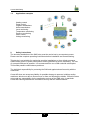
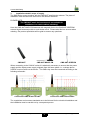
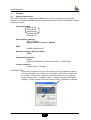
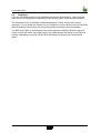
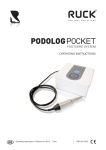
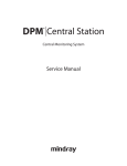
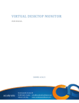
Comat SMS Relay Operating Instructions Kühn Controls AG, Gräfenhäuser Str. 14, D-75305 Neuenbürg, Germany www.kuehn-controls.de [email protected] Tel. +49 (0)7082-94 00 00 Fax +49 (0)7082-94 00 01 ba_smsrelay_0706e.doc Comat SMS Relay Content 1. SMS Relay Operating Instructions........................................................................................ 3 1.1 Short description of the CMS Comat Message System SMS Relay ..................................3 1.2 Short instructions................................................................................................................ 3 1.3 Application examples.......................................................................................................... 4 2. Safety instructions.................................................................................................................4 3. Installation details/ scope of supply...................................................................................... 5 4. Software................................................................................................................................ 6 4.1 System requirements.......................................................................................................... 6 4.2 Installation........................................................................................................................... 7 5. Run Mode............................................................................................................................. 8 5.1 LED status display.............................................................................................................. 8 5.1.1 GSM-LED......................................................................................................................... 8 5.1.2 Status-LED....................................................................................................................... 8 5.1.3 Inputs / Outputs................................................................................................................8 5.2 Power failure.......................................................................................................................9 5.3 Diagnose............................................................................................................................. 9 6 Configuration of the SMS Relay with the „FAST SMS Set“ ™ Software................................9 6.1 General............................................................................................................................... 9 6.2 Create connection............................................................................................................... 9 6.3 Edit Telephone book......................................................................................................... 10 6.4 Settings............................................................................................................................. 10 6.4.1 Automatic provider search............................................................................................. 11 6.4.2 Manual provider search................................................................................................. 11 6.5 Status messages...............................................................................................................12 6.6 Input configuration.............................................................................................................12 6.6.1 General.......................................................................................................................... 12 6.6.2 Parallel message handling............................................................................................. 13 6.6.3 Delayed switching on..................................................................................................... 14 6.6.4 Delayed switching off..................................................................................................... 14 6.7 Output configuration..........................................................................................................15 6.7.1 General.......................................................................................................................... 15 6.7.2 Timer function................................................................................................................ 15 7 Language selection.............................................................................................................. 16 7.1 General............................................................................................................................. 16 7.2 Change / expand language library.................................................................................... 16 8 Technical items.................................................................................................................... 17 8.1 Dimension......................................................................................................................... 17 8.2 Technical datas................................................................................................................. 17 Operating instructions SMS Relay 2 ba_smsrelay_0706e.doc Comat SMS Relay 1. SMS Relay Operating Instructions 1.1 Short description of the CMS Comat Message System SMS Relay The Comat CMS-10 SMS relay is a remote control and messaging system. Six digital inputs and four relay outputs with alternating contacts are monitored by means of a SMS (Short Message System) via a mobile telephone network* (SIM card determines the provider). The device’s own phone book saves up to 50 mobile phone numbers of the receivers. Each status change at the input sends a pre-defined message by SMS to the selected receivers. The receivers are processed cyclically, according to the order chosen. The outputs can be switched on and off by means of a pre-defined message by SMS. In order to obtain an overview of the state of the installation, the input and output status can also be queried by SMS. The relay outputs have a „time function“. The outputs are only switched on during the preset time. Unauthorised access can be controlled by activation of a password. The SMS relay sends out a message at regular intervals. The same thing happens if there is a power loss, whereby the SMS relay sends out a last message. If the power is restored, the CMS 10 sends back a further message. All these options can of course be switched on and off if required. The programming of the SMS Relay is carried out with the „FAST SMS Set“ tm programming software that is provided. In this way the settings can be configured conveniently and easily *GSM network: 850MHz, 900MHz, 1800MHz, 1900MHz (quad-band GSM module inside) 1.2 Short instructions 1. Switch off the SMS Relay 2. Place the SIM card in the card holder 3. Connect the RS232 interface of your PC or Notebook with the programming interface of the SMS Relay. Use the programming cable. 4. Now switch on the SMS Relay 5. As soon as the SMS Relay is ready (after about 100 sec), start the programming software FAST SMS Set (Status-LED and GSM-LED are blinking regularly) 6. Choose your prepared file or create a new file with your configuration. Please set the correct PIN code. 7. Select a free COM port (Menu Configuration – Select port) 8. Download the file to the SMS Relay ( download) 9. Wait until the SMS Relay is ready again (after about 100 sec) 10. Set the time and the date (Menu Configuration – Set time/date) Operating instructions SMS Relay 3 ba_smsrelay_0706e.doc Comat SMS Relay 1.3 Application examples Heating control Pump control Irrigation installations Alarm transmission Level monitoring Temperature monitoring Pressure monitoring Valve control Voltage monitoring 2. Safety instructions The electrical installation of the SMS relay must be carried out by a competent person. Please read the complete operating instructions before installation and commissioning. This device is not suitable for monitoring sensitive installations or time critical processes. GSM network failure or power interruptions cannot guarantee a secure monitoring. The use of a prepaid SIM card is possible. It is recommended to use a SIM card with subscription. This avoids possible credit balance problems. The individual responsibility for protecting the SIM card against abuse lies solely with the card owner. Comat AG does not accept any liability for possible damage to persons, buildings and/or machines, which occur due to incorrect use or from not following the details. Comat AG does not accept any responsibility for the application and use of the SMS relay. In particular Comat AG cannot guarantee the connection security with the mobile network. Operating instructions SMS Relay 4 ba_smsrelay_0706e.doc Comat SMS Relay 3. Installation details/ scope of supply The SMS Relay comes together with the CMS-ANT small device antenna. The place of installation must be taken into account for the antenna selection. PLEASE NOTE: The CMS-ANT small device antenna is not suitable for installation in a switch cabinet (shielding). Here the CMS-ANT-MAG/2.5M antenna with magnetic feet or the CMS-ANT-SPEZ/5M external signal antenna provide a much better result. Please take this into account when ordering. Our product specialists will be glad to answer any questions. CMS-ANT CMS-ANT-MAG/2.5M CMS-ANT-SPEZ/5M When connecting to the 230VAC mains it is absolutely necessary to ensure that the power supply and the inputs power supply originate from the same phase i.e. a voltage above 240VAC must not arise on the device. The SMS relay must be connected according to the following schematic: Connection CMS-10/AC110-240V Connection CMS-10/DC12-48V The regulations and common standards are to be followed for the electrical installation and the installation must be carried out by a competent person. Operating instructions SMS Relay 5 ba_smsrelay_0706e.doc Comat SMS Relay 4. Software 4.1 System requirements The „FAST SMS Set“ tm configuration software runs on the current Microsoft operating systems. The following minimum system requirements must be met in order that the software functions properly: Operating system: Windows98 WindowsNT WindowsME Windows2000 WindowsXP CPU computer capacity: 486er / 100MHz Recommended: Pentium I / 400MHz RAM: 256MB (WindowsXP) Hard disc storage capacity available 40MB Programming interface: RS232 USB (with USB-RS232- interface converter e.g. CMS-USB) *Screen resolution minimal: 1024 x 768 pixels *PLEASE NOTE: If the screen resolution is too low, the window of the programming software won’t be displayed in his normal size. That means some tabs or buttons will be invisible. To avoid this, change the screen resolution of your computer system. Select “Start” – “System controls” – “Display” and then the register “Settings”. Please set the screen resolution to 1024 x 768 pixels in minimum. Operating instructions SMS Relay 6 ba_smsrelay_0706e.doc Comat SMS Relay 4.2 Installation Once the CD-ROM is inserted, the installation menu starts automatically, if this is not the case then the CD-ROM can be started by double clicking „Start“ in the WindowsExplorer. The installation menu is available in different languages. Please choose the required language. You can install the software on your computer or start it directly from the CD-ROM without installing. Please follow the set-up programme instructions during installation. The SMS relay starts up automatically once power has been supplied. When the signal is strong enough the device will register itself in the GSM network (according to the SIM card settings, depending on provider). Both LEDs will display the actual device and network status. Operating instructions SMS Relay 7 ba_smsrelay_0706e.doc Comat SMS Relay 5. Run Mode 5.1 LED status display The SMS relay has two LEDs, the GSM LED und the status LED. Both LEDs can be seen from the outside and are located below the cover. The following states are displayed: 5.1.1 GSM-LED - flashing regularly (every second) Module is not registered in the GSM network. - short flashing (approx. every three seconds) Module is registered but there is no communication - Continuous lighting Communication connection is made - Irregular flashing Data are transmitted (SMS) 5.1.2 Status-LED - dark LED - intermittent flashing (irregular) - short flashing (like GSM LED, approx. every 3s) 1x - short flashing (like GSM LED, approx. every 3s) 2x - short flashing (like GSM LED, approx. every 3s) 3x - flashing regularly (every second) 1x - flashing regularly (every second) 2x - flashing regularly (every second) 3x Device does not run Device starts up Device runs, everything OK no credit left Clock not adjusted Module in initial state configuration error communication error 5.1.3 Inputs / Outputs In addition the states of the inputs and outputs are displayed by means of an LED. These LEDs are designated as follows: Inputs I1, I2, I3, I4, I5, I6 (LED lighting = input is switched on) Outputs Q1, Q2, Q3, Q4 (LED lighting = output is switched on) Inputs Status-LED GSM-LED Outputs LED positions of the SMS Relay Operating instructions SMS Relay 8 ba_smsrelay_0706e.doc Comat SMS Relay 5.2 Power failure Short power failures (t < 1s) are tolerated by the power supply and do not change the module status. Longer power failures (t ≥ 1s) are registered and can trigger an SMS alarm message depending on the adjustment. Afterwards the device shuts down. After restarting the device the states of the outputs and the registration of the SMS Relay in the GSM network are restored to the same status as before the voltage failure (Memory function). 5.3 Diagnose The SMS Relay together with the programming software „FAST SMS Set™“ allow to display the actual signal quality. For that function the SMS Relay has to be connected with a PC / laptop via the programming cable. To get to the diagnose select “Configuration – Diagnose” from the menu in the programming software. In addition to the signal quality the diagnose will display some more information like different version numbers of the device and the firmware. 6 Configuration of the SMS Relay with the „FAST SMS Set“ ™ Software 6.1 General The SMS Relay is configured and prepared fro use with the „FAST SMS Set™“ software. The SMS Relay can be prepared before installation i.e. the SMS Relay configuration (telephone book creation, input messages) can be created without connecting to the device. In order to do this the software is started, a new or existing file opened and edited. The file created needs only to be downloaded to the SMS Relay with the CMS-RS232 programming cable. In offline mode the diagnostics are not active. The diagnostics can only be accessed once the SMS Relay is connected by the RS232 serial interface to the PC. 6.2 Create connection • Switch off the SMS Relay • Insert the SIM card • Connect the RS232 interface of your PC or Notebook with the SMS Relay programming interface using the CMS-RS232 programming cable. If your PC or Notebook does not have an RS232 interface then use a CMS-USB interface converter. With this you can directly connect the programming cable to one of your USB inputs. • Switch on the SMS Relay • As soon as the Status-LED of the SMS Relay lights permanently, you can start the software. • Choose the required file or create a new one. • For transmission, choose the required COM port on your PC. This is carried out in the „Configuration – Select port“ menu. Now you are ready to configure the SMS Relay according to your needs or to download the prepared files. Operating instructions SMS Relay 9 ba_smsrelay_0706e.doc Comat SMS Relay 6.3 Edit Telephone book The software offers the possibility to manage up to 50 telephone numbers. New – capture of a new phone number Editing – editing of an already existing and labelled phone number Deleting – deleting of an existing and labelled phone number Checking – checks whether the labelled entry is already captured in the telephone book. Please enter the phone number in international format (i.e. with country code and prefix) , e.g. +41793333333. (+41 Switzerland; +49 Germany, +31 Holland, etc) In the„Name“ data field the list can be sorted in ascending or descending alphabetical order. The sorting does not influence entries which have already been used. SMS Relay Phonebook editor 6.4 Settings You can now configure the SMS Relay according to your application. The default settings for SMS transmission contain important general data which help identify the device. The SIM card can be protected with PIN code just like for normal mobile phone operation. The PIN request is activated and the PIN code is inputted in the required field. This concerns PIN1. Further information can be obtained from the SIM card leaflet. Likewise the process of unblocking the SIM card after three incorrect inputs of PIN1 is described. In order to do this the SIM card must be removed from the SMS Relay and inserted into a mobile phone. Now the card can be unblocked according to the network providers details. Operating instructions SMS Relay 10 ba_smsrelay_0706e.doc Comat SMS Relay SMS Relay Settings 6.4.1 Automatic provider search The automatic provider selection depends on the SIM card that is inserted in the SMS Relay. The provider details and rights on the SIM card are accepted. Basically the provider is preassigned when the SIM card is purchased. With the „automatic“ setting the network provider is chosen according to the SIM card. This is useful if the card is used in the home network. Other GSM networks can be used abroad with the same SIM card according to the roaming contracts. 6.4.2 Manual provider search For manual provider searches the available GSM networks are scanned several times. The results of this search are displayed by a list of networks. By clicking „Search“ („search“) with the mouse the networks found will be displayed. The required network can now be chosen. The SMS service centre number can be taken from the SIM card documentation. Normally this number is already available on the SIM card. This number depends on the GSM provider. In the „SMS Relay description“ field a name for the SMS relay can be entered. All outgoing messages from this SMS Relay are provided wit this name for identification. The available number of characters for a message will be shortened according to the number of characters of the name. The actual number of characters available will be displayed. PLEASE NOTE The display of special characters in the GSM network can cause problems. Please use only text characters and figures. The programming software identifies special characters and an errror messages will occur. Operating instructions SMS Relay 11 ba_smsrelay_0706e.doc Comat SMS Relay The receiver of the status messages can now be chosen from the telephone book. In order to do this click with the mouse pointer on the expand arrow and select the required entry. 6.5 Status messages The SMS relay can send the following status messages: • Remote enquiry of all inputs and outputs The device offers the possibility to interrogate all input and output states by SMS. A code word is therefore sent by SMS to the device. The code word can be changed. The standard code word is: ?#all The answer is send to the same phone number (phone number identification). The states of the inputs and outputs are displayed as follows in the SMS message: I:00010 Eingänge 1 bis 6 O:0101 Ausgänge 1 bis 4 0 = AUS / 1 = EIN 0 = AUS / 1 = EIN • Message at the start A message will be sent with this report according to a preset number for each start up (switching on / return of power) of the SMS relay. (According to the phone number entries in the list.) The message contents can be edited. • Messages in case of power failure In case of voltage failure the SMS relay sends a last signal to receiver No.1 to 5 of the status messages. The message contents can be edited. • Periodical message The periodic message provides information. A message is sent periodically. The message can be sent daily (time), weekly (time, weekday) or monthly (time, date). The message contents can be edited. It is for checking functionality or operation confirmation. PLEASE NOTE The display of special characters in the GSM network can cause problems. Please use only text characters and figures. The programming software identifies special characters and an errror messages will occur. 6.6 Input configuration 6.6.1 General The SMS Relay has 6 inputs. Each one of these inputs can send an SMS message, which can be chosen at will, to a predefined telephone number either in case of activation or loss of the input signal (up to 5 various numbers). PLEASE NOTE Please mind every input needs at least one phone number in his list. It doesn’t matter if the input is connected or not or the status messages are set inactive. If the receiver field is empty, the software can’t save the file or the file can’t be downloaded to the SMS Relay. Basically two events can trigger an SMS: the change from LOW-to-HIGH and the inverse the change from HIGH-to-LOW. One or both events can be activated. A separate text message can be entered for each event. If the SMS Relay does not receive an acknowledgement within a certain preset time from the receiver, the event message will be sent to the next receiver. This means that the device Operating instructions SMS Relay 12 ba_smsrelay_0706e.doc Comat SMS Relay runs through the 5 allocated receiver numbers and restarts afterwards with the first number (The number of run throughs can be pre-defined). As soon as the device receives a confirmation the process is stopped. If this is not the case the message will be sent to the next receiver(after expiry of the preset time) . If the acknowledgement is inactive all receivers who are allocated to that event will receive a message without repetition. If the confirmation code word is not activated, the phone number identification is carried out as a security check and it is sufficient to send an empty SMS to the SMS Relay. PLEASE NOTE The display of special characters in the GSM network can cause problems. Please use only text characters and figures. The programming software identifies special characters and an errror messages will occur. 6.6.2 Parallel message handling It can occur that the status of several inputs change at the same time or within the actual running message cycle. Every input needs a individual message. Every change of the status, who triggers an event message, will be handle in order of the appearance. Every message will be handle individual. That means the message handling for every input will be handle individual. Several events at the same time can trigger corresponding messages. Example: The events “pump breakdown” and “over temperature” (two different inputs) are appearing at the same time individual handling of the two events. Operating instructions SMS Relay 13 ba_smsrelay_0706e.doc Comat SMS Relay Input configuration 6.6.3 Delayed switching on If there is an input signal, the respective message can be time delayed, i.e. the SMS relay only sends the pre-defined message after expiry of the preset time, if the signal is still there. In other words the input signal is ignored during this time. Time delays of 0.1 seconds to 99.9 hours are possible. This time function must be activated. 6.6.4 Delayed switching off If an input changes from HIGH to LOW, i.e. there is no longer an input signal, a delayed switching off can also be activated here. The SMS relay sends the predefined message after the preset time, unless the signal is no longer present. Time delays of 0.1 seconds to 99.9 hours are possible. This time function must be activated. Operating instructions SMS Relay 14 ba_smsrelay_0706e.doc Comat SMS Relay 6.7 Output configuration 6.7.1 General The SMS Relay has 4 relay outputs (change over contacts, 10A, 250V). The outputs can be controlled by an SMS i.e. they can be switched ON and OFF. Each output can be activated individually. The message text can be chosen at will. However the device only reacts to the exact expression i.e. the message must correspond exactly with the inputted expressions. Upper and lower cases are ignored, spaces between the words and other characters must be correctly inputted. Switching commands are only accepted from numbers which are in the telephone book . This means, an output can be switched on or off per SMS. The SMS Relay acknowledges this after carrying out the actions. Text messages for switching on and off can be entered. An additional message can be defined, if an output is already at the required state and consequently no action will be carried out. These messages are always transmitted to the sender. Output configuration 6.7.2 Timer function An output can be switched off again after a certain time with the help of a timing function, without having to send the switching off command by SMS. Time delays of 0.1 seconds to 99.9 hours are possible. Switches the output off after expiry of the set time, a message is sent to confirm this action. If a switching off command is sent before expiry of the set time, this will be taken into account. This timing function is normally switched off and therefore must be activated. PLEASE NOTE: The switching times don’t allow a monitoring or a controlling of time critical processes due to the tolerances and GSM network delays. Operating instructions SMS Relay 15 ba_smsrelay_0706e.doc Comat SMS Relay 7 Language selection 7.1 General The SMS Relay configuration software, Fast SMS Set, has the possibility to change the language. The languages can be chosen from a library. It is not necessary to re-start the programme after selecting the language. In order to do this select “Language – Select language“ and then the required language from the library. Language selection Lanaguage editior 7.2 Change / expand language library The available languages can be changed or expanded. The „Language editor“ can be started via the „Language – Edit language” function. The required language is selected from the „Language – Open Language File“. The complete menu navigation will be displayed on the left side in English. This is also the „master file“. The menu navigation appears on the right side in the language selected. The menu items to be changed can be selected with the cursor or by mouse click. In the „Message“ window the text can be overwritten and then be confirmed with the „Approve Changes“ button. The changes will not be effective without this confirmation. When all the changes have been implemented the file must be saved with „Save Language File „. Now the language editor can be exited via „Close“ or „Exit“ . Operating instructions SMS Relay 16 ba_smsrelay_0706e.doc Comat SMS Relay 8 8.1 Technical items Dimension SMS Relay - Dimension 8.2 Technical datas Operating voltage Power consumption Switching capacity Temperature range Inputs Outputs Provider (Phone / Network) Operating instructions SMS Relay AC 110-240V~ 50/60Hz DC 12-48V max. 10% 8VA / 6W 6W 4x 10A 250V Temp: -25…+55°C Rel. humidity: 5…95% (non condensing) Protection: IP 20 6x digital trigger level 85V~ 6x digital trigger level 9.5V 4x CO contacts User selectable (depending on SIM card) 17 ba_smsrelay_0706e.doc