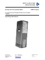
1
Density and Concentration Meter DIMF-Compact For continuously measuring the density and concentration of liquids Operating Instructions Bopp & Reuther Messtechnik GmbH Am Neuen Rheinhafen 4 67346 Speyer Germany Phone : +49 6232 657-0 Fax: +49 6232 657-505 [email protected] www.bopp-reuther.de A-EN-06535-00Rev.B 05/2015 Page 1 of 14 Operating Instructions Density Meter DIMF-Compact Contents Contents .................................................................................................................................................. 2 Introduction .............................................................................................................................................. 3 I. Transport, Delivery, Storage ................................................................................................................ 3 II. Warranty .............................................................................................................................................. 3 III. General Safety Information ................................................................................................................ 3 1. Technical Data..................................................................................................................................... 4 1.1 Density transducer ........................................................................................................................ 4 1.2 Evaluation electronics ................................................................................................................... 4 1.3 Factory setting ............................................................................................................................... 5 2. Intended Use ....................................................................................................................................... 5 3. Measuring Principle ............................................................................................................................. 5 4. Installation ........................................................................................................................................... 6 4.1 Installing the device....................................................................................................................... 6 4.2 Required differential pressure ....................................................................................................... 6 4.3 Examples of installation positions ................................................................................................. 7 5. Assembly ............................................................................................................................................. 7 5.1 Density transducer ........................................................................................................................ 7 5.2 Piping ............................................................................................................................................ 7 5.3 Process connections ..................................................................................................................... 8 6. Electrical Connection ........................................................................................................................... 8 6.1 Connection .................................................................................................................................... 8 7. Commissioning .................................................................................................................................... 8 8. On-Site Adjustment ............................................................................................................................. 8 8.1 Zero adjustment with water ........................................................................................................... 8 8.2 Adjustment with any density.......................................................................................................... 9 9. Configuration, Operation ..................................................................................................................... 9 10. Maintenance ...................................................................................................................................... 9 10.1 Cleaning ...................................................................................................................................... 9 10.2 Zero point adjustment ................................................................................................................. 9 11. Error Detection / Troubleshooting ................................................................................................... 10 11.1 Errors caused by the liquid........................................................................................................ 10 11.2 Errors caused by the connection provided by the customer ..................................................... 11 11.3 Errors caused by the electronics ............................................................................................... 11 12. Service ............................................................................................................................................. 11 13. Appendix .......................................................................................................................................... 12 13.1 Wiring diagram .......................................................................................................................... 12 13.2 Dimensions ............................................................................................................................... 12 13.3 Example of configuration data log............................................................................................. 13 13.4 EC Declaration of Conformity (August 2013) ............................................................................ 14 Page 2 of 14 Technical details subject to change. A-EN-06535-00Rev.B Bopp & Reuther Messtechnik GmbH Density Meter DIMF-Compact Operating Instructions Introduction I. Transport, Delivery, Storage Storage and transport: Protect devices against humidity, soiling, impacts and damage. Delivery inspection Upon receipt, check the delivery for completeness. Compare the device data with the data on the delivery note and in the order records. Report any in-transit damage immediately upon delivery. Damages reported at a later date shall not be recognised. II. Warranty Please refer to the contractual terms and conditions relating to delivery for the scope and period of warranty. Warranty claims shall be conditional to correct installation and commissioning in accordance with the operating instructions of the device. III. General Safety Information Read and observe these operating instructions thoroughly and keep them available for reference. Installation has to be carried out by qualified personnel. ! Always observe the generally acknowledged rules of technology and these operating instructions during installation and operation of the device We shall accept no liability for improper handling, use, installation, operation and maintenance of the device. In the case of corrosive media, the material resistance of the oscillating pipe has to be checked. Damaged devices must be shut down. Bopp & Reuther Messtechnik GmbH A-EN-06535-00Rev.B Technical details subject to change. Page 3 of 14 Operating Instructions Density Meter DIMF-Compact 1. Technical Data 1.1 Density transducer Density range 500 to 1500 kg/m³ Calibration range 800 to 1200 kg/m³ Up to 0.1% ( 1 kg/m³) Measuring accuracy depending on the model better than 0.02 % ( 0.2 kg/m³) Repeatability Medium temperature* 0°C to + 80°C Ambient temperature* 0°C to + 60°C Via integrated Pt1000 in accordance with DIN Class A directly in the transmitter Temperature compensation Operating pressure 6 bar depending on the type of connection Liquid Pumpable liquids Material: wetted parts Stainless steel 1.4571 (others on request) Material: Transmitter housing stainless steel 1.4571 Smallest inside diameter 2 x 7 mm parallel Weight approx. 1.2 kg Process connections Internal thread G ¼“ All percentages refer to a density of 1000 kg/m³ at 20°C. For exact specifications of the device model, see the configuration data sheet of the supplied device. * In the standard version of the device condensation must be prevented, i.e. the measured temperature must be higher than the ambient temperature. Welded special version of the device is available for any temperature within the ranges specified above. 1.2 Evaluation electronics Functions Output signal Communication protocol The electronics integrated in the sensor housing ensures the oscillating element in the density transducer is excited at its natural frequency, compensates temperature influences and provides the operator with measuring results via an RS232 data interface Operating density, temperature Through specific programming of reference density, concentration, °Brix or other parameters derived from density Measured values are transferred to a PC via the RS232 interface Depending on the output format: 9600 baud, 7 data bits, 1 stop bit, even parity or 9600 baud, 8 data bits, 1 stop bit, no parity Power supply Communication with the module occurs via a customary terminal program, e.g. Windows® terminal, Hyper terminal… 15 – 24 V DC , < 20 mA Electrical connection Via connector Cable specification (Four core) cable length max. 30 m Page 4 of 14 Technical details subject to change. A-EN-06535-00Rev.B Bopp & Reuther Messtechnik GmbH Density Meter DIMF-Compact Operating Instructions Ambient temperature 0°C to + 80°C Storage temperature -20°C to + 80°C Degree of housing protection IP65 Housing dimensions 50 (D) x 175 (L) x 60 (H) mm Calibration and configuration According to ordering data at Bopp & Reuther Messtechnik GmbH 1.3 Factory setting The density transducers of the DIMF-Compact series have been parameterised according to your specifications. After switching on the power supply, DIMF-Compact outputs measured values once a second. 2. Intended Use The DIMF density transducer allows the continuous measurement of the density or concentration of liquids and liquid mixtures. The proven oscillating element principle ensures a high-degree of accuracy in combination with outstanding long-term stability. The simple construction assures reliable operation even under tough process conditions. 3. Measuring Principle The real sensor of the density transducer is an oscillating element in the form of a tube bent into a tuning fork. The liquid to be measured passes continuously through this element. Excited electromagnetically by an excitation coil, it will oscillate at its natural frequency. Changes in the density of the liquid lead to changes in the natural frequency. This change in frequency, sensed by a pick-up coil, represents the measurement effect. An additional built-in resistance thermometer measures the process temperature, which can also be used to equalise the temperature influence in the transducer. Each density transducer is calibrated with various liquids of different densities. The transducer constants for calculating the density from the frequency, the calibration temperature and the correction coefficients for the temperature influence can be seen in the configuration data protocol (see section 13.3 for example). Bopp & Reuther Messtechnik GmbH A-EN-06535-00Rev.B Technical details subject to change. Page 5 of 14 Operating Instructions Density Meter DIMF-Compact 4. Installation 4.1 Installing the device The device can be installed directly in the main product line for a flow rate of up to 10 ℓ/min. Installation in a by-pass is recommended for higher flow rates or measurements at containers. For other viscosities, differing pressure losses have to be considered (see details in section 4.2). Density transducers of the DIMF series measure independent of the flow rate and also at zero flow rate. Their application is, therefore, normally problem-free. However, it has to be ensured that the operating flow rate in the transducer - updates the sample fast enough - equalises the temperature in the transducer - prevents gas bubbles or any sediment collecting in the oscillating tube - does not cause cavitation in the oscillating tube - does not cause wear through abrasives CAUTION: The pressure in the product line should never fall below the vapour pressure. Keep the density transducer out of direct sunlight. If necessary, heat insulation has to be provided. With higher medium temperatures, make sure the integrated electronics is not exposed to temperatures above 80°C. 4.2 Required differential pressure From experience, a flow rate of 1 to 6 ℓ/min is recommended to ensure a sufficiently fast sample update. Max. flow rate: 0 to 10 ℓ/min Pressure loss curve Pressure loss for water 20°C Druckverlustkurve zumfor DIMF-Compact Pressure loss curve DIMF-Compact Druckverlust Pressure loss [mbar] [mbar] 2500 2000 1500 1000 500 0 0 5 10 15 20 25 Flow rate [ℓ/min] Durchfluss Durchfluß [l/min] Page 6 of 14 Technical details subject to change. A-EN-06535-00Rev.B Bopp & Reuther Messtechnik GmbH Density Meter DIMF-Compact Operating Instructions 4.3 Examples of installation positions Standard installation position Clean liquids Also lower flow rates Without gas admixtures Any Installation position for liquids which are subject to sedimentation. Installation position for liquids in which gas bubbles can occur. The arrow indicates the possible direction of flow. 5. Assembly 5.1 Density transducer - Handle with care; do not knock Install in the by-pass or directly in the product line De-aerate before commissioning Provide a constant flow through the density transducer Any flow direction is possible, see section 4.3 For the flow rate, see details in section 4.2 (provides current liquid sample, prevents sedimentation) Prevent generation of vapour bubbles - Minimum diameter of the connecting pipe: 6 mm Fit sampling connection laterally if the main line is horizontal Supply pipe should be as short as possible If necessary, provide heat insulation for supply pipe If necessary, provide flushing connections close to the density transducer 5.2 Piping Bopp & Reuther Messtechnik GmbH A-EN-06535-00Rev.B Technical details subject to change. Page 7 of 14 Operating Instructions Density Meter DIMF-Compact 5.3 Process connections Ensure that the transducer connection is compatible with the piping connections. See the supplied configuration data sheet for the type of connection of your density transducer. Model with quick assembly block 6. Electrical Connection 6.1 Connection - The power supply and the data lines are connected by the customer in the connector (see section 13.1) - For the connector type, see Appendix 7. Commissioning - Flush pipes before connecting the density transducer - Ensure that all connections are tight - De-aerate the density transducer - Switch on the power supply 8. On-Site Adjustment 8.1 Zero adjustment with water Fill the device with distilled water. Make sure there are no gas bubbles in the device. The density output must be similar to the water density. Send the letter "W" via the RS232 interface. The device measures the density and calculates the water density relating to the current temperature. The K0 value is corrected using these two values and saved again in the device. After adjustment, the device displays the water density. Page 8 of 14 Technical details subject to change. A-EN-06535-00Rev.B Bopp & Reuther Messtechnik GmbH Density Meter DIMF-Compact Operating Instructions 8.2 Adjustment with any density Fill the device with the medium. Make sure there are no gas bubbles in the device. The medium density for the current temperature must be known. Adjustment takes place until the operating density has been reached. Send the letter "A" and the density via the RS232 interface, e.g. 998.12 kg/m³, as follows: "A0998.120". Pay particular attention to the number of characters and the decimal point! The device measures the current density and calculates the offset for the density received. The adjustment value is corrected and saved in the device. After adjustment, the device displays the exact transferred density. If problems occur after the on-site adjustment, the factory calibration data can be reset by sending the letter "B" to the device via the RS232 interface. 9. Configuration, Operation Operation at the device itself is not possible. Only the on-site adjustment is available for the configuration (see chapter 8) 10. Maintenance Maintenance work involves cleaning and zero point adjustment. 10.1 Cleaning The density transducer should be cleaned according to the sedimentation tendencies of the measured liquid. The simplest cleaning method is to increase the flow velocity through the density transducer to the maximum permissible value for a few minutes in order to flush away any sediment and solids. If this measure is not successful, the density transducer should be cleaned with special detergent if flushing connections are provided. Always observe the corrosion resistance of the density transducer material. 10.2 Zero point adjustment Abrasion, sedimentation or corrosion can cause the zero point of the density transducer to shift. The zero point shift can be established via a comparison measurement and rectified by an on-site adjustment (see chapter 8 and 11). Bopp & Reuther Messtechnik GmbH A-EN-06535-00Rev.B Technical details subject to change. Page 9 of 14 Operating Instructions Density Meter DIMF-Compact 11. Error Detection / Troubleshooting Periodical inspections of the density transducer facilitate error detection and can provide information about possible error sources. The inspection can usually be limited to a comparison between the value measured by the density transducer and a reference measurement (e.g. sampling with laboratory measurement or a comparison density meter connected in series). It is essential that the reference measurement is sufficiently reliable and accurate (if necessary, calibratable) to ensure correct results. During this comparison, ensure that the reference conditions are comparable to actual operating conditions (if necessary, take the temperature coefficient of the used liquid into consideration). If the value measured by the density transducer does not match the result of the reference measurement, carry out the following measures: - Inspect the density transducer for serious damages (temper colours on the housing due to high temperature as well as obvious mechanical damage, e.g. connector, etc.) - Look for process-related malfunctioning (e.g. empty product line, gas bubbles) A seriously damaged density transducer must be disassembled and returned to Bopp & Reuther Messtechnik GmbH (see chapter 12). Otherwise, troubleshooting should be carried out as described below. There are three general sources of error: - Errors caused by the liquid (see section 11.1) - Errors caused by the connection provided by the customer (see section 11.2) - Errors caused by the electronics (see section 11.3) 11.1 Errors caused by the liquid Error Negative measuring error Unstable display Possible reason Air locks or gas bubbles in the product or inside the transducer Positive measuring error Long-term drift Sedimentation in the transducer Negative measuring error Long-term drift The display does not change or is too slow The displayed temperature is too low Page 10 of 14 Corrosion Abrasion Flow in the transducer is too low or zero Technical details subject to change. Remedy Increase pressure in the product line De-aerate the product line Increase the flow velocity in the transducer Increase the flow velocity in the transducer (recommended value, e.g. 6 ℓ/min) Remove any sediments in the transducer using an appropriate solvent (observe the corrosion resistance of the transducer) Inspect the material resistance of the transducer Reduce the flow velocity in the transducer (recommended value, e.g. 1 ℓ/min see section 4.2) Open all shut-off valves Increase the flow velocity in the transducer A-EN-06535-00Rev.B Bopp & Reuther Messtechnik GmbH Density Meter DIMF-Compact Operating Instructions 11.2 Errors caused by the connection provided by the customer - Check the power supply connection and the communication lines (see section 13.1). After switching on the power supply, a sound is audible in the device at a pitch of approx. 400 Hz. If this sound is not audible, the power supply has most probably been connected incorrectly - Measured values are not output via the RS232 line -> check correct connection of the communication lines - Check the protocol settings in the terminal program (see communication - protocol, see section 1.2) 11.3 Errors caused by the electronics - No oscillating noise audible at a pitch of approx. 400 Hz -> see chapter 12 - Device oscillates but measured values are not output -> see chapter 12 - Unrealistic measured values are output that deviate from the actually measured value by hundreds of kg/m³ - Air / Sediment in the device, see section 11.1 - Possibly failed on-site adjustment -> reset factory calibration data (see section 8.2) - Measured values still deviate significantly after resetting the factory calibration data -> see chapter 12 12. Service Please contact our Service Department with regard to the density and concentration meter: Bopp & Reuther Messtechnik GmbH Dept. MRV-S Service Am Neuen Rheinhafen 4 67346 Speyer, Germany Phone: +49 6232 657 – 402 Fax: +49 6232 657 – 561 Bopp & Reuther Messtechnik GmbH A-EN-06535-00Rev.B Technical details subject to change. Page 11 of 14 Operating Instructions Density Meter DIMF-Compact 13. Appendix 13.1 Wiring diagram Pin 1 Pin 2 Pin 3 Pin 4 Pin 5 15 – 24V GND RS232 control commands from PC to DIMF RS232 measured values from DIMF to PC Leave unconnected The following connector must be used by the customer: Binder cable connector round series 712 5-pole e.g. Bopp & Reuther Messtechnik, item no.: 2-08-45001-020 e.g. manufacturer no.: 99-0413-00-05 e.g. purchase via RS: RS order no.: 115-2764 Purchase via R.E.D.: Order no. 99-0413-00-05 13.2 Dimensions All dimensions in mm Page 12 of 14 Technical details subject to change. A-EN-06535-00Rev.B Bopp & Reuther Messtechnik GmbH Density Meter DIMF-Compact Operating Instructions 13.3 Example of configuration data log Kalibrierzertifikat DIMF-Compact Calibration certificate DIMF‐Compact Kunde / Customer: Musterfirma Prüfmedien / Calibration liquids: Alkohol ‐ Wasser / Alcohol ‐ Water Seriennummer / Serial No.: 10037350 Aufnehmertyp / Test item: DIMF Compact Prüfdatum / Test date: 09.09.2010 Prüfer / Tester: Schmidt Kalibrierungstabelle / Calibration table Dichte Referenz Dichte Prüfling Istwert [kg/m³] Sollwert [kg/m³] Density of ref. Density Test item Prüfmedien Calibration liquids Frequenz Prüfling [Hz] Frequency Medium / Liquid 1 371,417 1003,376 Medium / Liquid 2 370,784 1000,433 Medium / Liquid 3 377,337 834,462 Medium / Liquid 4 376,964 825,884 Fehler [kg/m³] Error Temperatur [°C] Temperature Fehler [%] Error 15,87 -0,0021 0,0210 25,69 0,0041 -0,0408 34,99 0,0071 -0,0597 44,71 -0,0018 0,0150 1003,355 1000,474 834,522 825,869 1,0 0,8 Aufnehmerkonstanten / Calibration constants: K2: KT1: Lambda: 0,6 -3354,333984 kg/m³ 6,050909 kg/(m³•s²) -0,002517 1/K 16,500000 kg/(m³•K) Messverfahren / measurement method: Serialnr. 38400 Master 1 Kalibrierung gegen Mastergerät Calibration against reference 0,4 Fehler / Error [kg/m³] K0: 0,2 0,0 750 800 850 900 950 1000 1050 ‐0,2 ‐0,4 ‐0,6 ‐0,8 Kalibrierung der Master gültig bis Calibration master valid until 02.2011 ‐1,0 Dichte / Density [kg/m³] Umgebungstemperatur Kalibrierraum 20°C Ambient temperature calibration laboratory Dieses Protokoll wurde automatisiert erstellt und ist ohne Unterschrift gültig. Druckdatum / printed: 9.9.2010 This protocol was created automatically and is valid without signature Bopp & Reuther Messtechnik GmbH A-EN-06535-00Rev.B Technical details subject to change. Page 13 of 14 Operating Instructions Density Meter DIMF-Compact 13.4 EC Declaration of Conformity (August 2013) Page 14 of 14 Technical details subject to change. A-EN-06535-00Rev.B Bopp & Reuther Messtechnik GmbH