1
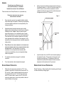
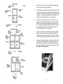
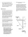
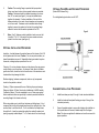
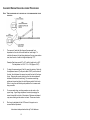
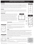
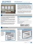
PHILIPS
PRODUCTS
MANUFACTURED HOUSING
VINYL WINDOW
INSTALLATION INSTRUCTIONS
(EXCLUDES
PHILIPS PRODUCTS
PHONE NUMBER:
574/296-0000
STORM WINDOWS)
LIT-1610
3/05
REV 2
GENERAL
PROPER INSTALLATION IS ESSENTIAL FOR THE
ACCEPTABLE PERFORMANCE OF THIS WINDOW.
IMPROPER INSTALLATION WILL VOID THE WARRANTY.
2.
These instructions are for Philips Products, Inc. vinyl windows only.
PLEASE
Check the squareness with diagonal measurements (see figure 1).
The difference between 1 to 4 and 2 to 3 should not exceed 1/4". If
the R.O. does not conform to these requirements, it must be
modified so that the sill is square to the floor within tolerance and
the diagonals are within the 1/4" allowance.
READ THESE INSTRUCTIONS COMPLETELY
Figure 1
BEFORE INSTALLING THE WINDOW.
1.
These instructions represent an acceptable installation method.
Other methods may be acceptable. Determining the acceptability
of alternate installation methods is the sole responsibility of the
housing manufacturer.
2.
Appropriate personal protective equipment (such as safety
glasses, gloves, steel-toed boots, etc.) should be worn during the
installation process. Caution: Weight of products requires
proper lifting techniques. Use a reasonable number of people
with the required strength to carry, lift, and install the window unit.
These instructions are not intended to address all of the safety
issues associated with the installation of these windows; it is the
responsibility of the housing manufacturer to establish appropriate
safety practices.
3.
PHILIPS PRODUCTS, INC.
DOES NOT WARRANT THAT THE PRODUCTS AND
INSTRUCTIONS PROVIDED COMPLY WITH ALL APPLICABLE BUILDING CODES
AND REGULATIONS.
It is the responsibility of the housing
manufacturer to insure the products and methods used in
construction and installation conform to all applicable building
codes and regulations.
4.
For casement style windows, see page 9, for additional
instructions.
5.
Do not leave windows in direct sunlight when wrapped.
ROUGH OPENING PREPARATION
1.
Make certain the rough opening (referred to as "R.O." in the
remainder of document) is correctly sized and constructed. The
R.O. must be ¼" greater in width and height than the portion of
the window that fits in the R.O. The R.O. sill must be square
within 1/8" across its width. However, if the R.O. sill is out of
square by a greater amount, it may not be possible to shim and
square the window in the opening.
2
3.
Inspect the exterior face of the R.O. where the mounting flange of
the window will contact. This area must not have gaps or voids
beneath the mounting flange. The sheathing or exterior wall
material that the window will be fastened to must be structurally
adequate so that the window unit is fully anchored.
WINDOW INSPECTION AND PREPARATION
Window Terminology – Become familiar with the terminology used throughout these instructions by studying figure 2.
3
Figure 2
1.
Measure the window prior to proceeding with the installation to
ensure that it matches the rough opening.
2.
These windows are fabricated with fusion welded joined corners.
Care should be exercised in the handling of the products as it is
possible to crack the welded outer frame. Inspect the outer frame
for damage. If frame is cracked, fractured, or damaged due to
handling, contact Philips Products, Inc. for instructions.
3.
Inspect the mounting flanges to ensure they have not been
damaged or distorted during shipping or handling to the extent
that they will not seat flat against the exterior perimeter of the
R.O. If damaged or distorted, straighten the mounting flange so
that it will make contact with the exterior face of the wall or
contact Philips Products, Inc. for instructions.
4.
Windows must always be closed and locked during installation.
Make sure there are no gaps or voids between the window
mounting flange and the exterior perimeter of the R.O. Gaps or
voids in this area may provide a path for water and air to enter.
5.
It is possible to install the window "upside down" and/or "inside
out" which will cause the unit to operate incorrectly, thereby
voiding the warranty. Note: The weep holes are always at the
bottom of the window at the exterior face (see figure 2). Never
fill, modify, or block weep holes.
Figure 3
4
5
6.
Apply a ¼" continuous bead of pumpable sealant to the back
side of the mounting flange (see figure 3), in line with prepunched holes. (Caution: If the window units are pre-sealed prior
to installation, a skin may form on the sealant, causing a potential
for failure. Refer to the sealant manufacturers instructions for
sealant curing time. Be sure to install the window before the
sealant sets up on the mounting flange.)
WINDOW INSTALLATION
1.
Place the window in the R.O. with the window sill resting on the
R.O. sill. If the R.O. sill is not square to the floor and if you have
elected to shim the window, then place shims beneath the low
corner of the unit until the sill of the unit is square. Shims must
be placed beneath the extreme corners of the window frame;
additional shims must be placed every 12" on center to fully support the weight of the unit. Shims may be used at the
frame/jambs if these frame/jambs are not straight and plumb; use
enough shims to straighten and plumb the frame/jambs. Shims
should not be used at the frame head of a unit; if R.O. header
deflects, building loads will be transferred to window, causing
improper operation or failure of window.
2.
Center the window from left to right but do not remove the sill
from contact with the R.O. sill and any shims that were required to
square the sill of the unit. When installing windows it is required
to use corrosion resistant fasteners that produce a minimum of 1"
penetration into the framing members.
3.
While holding the window flat against the exterior of the wall, start
a fastener in the approximate center of one of the frame/jamb
mounting flanges. Continue installing fasteners in the following
order; center of opposite frame/jamb, center of head and center of
sill. Note: If scaffolding interferes with the top of the window, it is
acceptable to install this later when it is more accessible.
4.
Warning: Fenestration products are not to be used with
corrugated metal siding.
5.
After the fasteners have been installed through the midpoint of
each mounting flange, it is recommended that you re-check the
window to be certain it is centered from side to side in the
opening, and that the window frame members are straight and
that the window frame is square, (measure opposite corners of
the window frame in a manner similar to measuring the diagonals
of the R.O., it should be within 1/8"). Before proceeding, it is
recommended that you check to ensure window operates
properly. If it does not, remove fasteners and reinstall window as
per above instructions. If shipping block(s) is present, remove at
this time.
Warning: Do not over drive fasteners, to do so
will fracture or unduly deform the mounting
flange and compromise the seal. Use caution in cold
weather when installing fasteners through the nailing
fin, the vinyl material becomes more brittle as
temperatures decrease. Do not apply fasteners
or staples through any other surface of the
window other than the Philips specified areas
and/or the mounting flange. Failure to comply
may void any manufacture warranty.
6
Figure 4
7
6.
7.
Caution: The mounting flange is provided with pre-punched
holes, never leave holes or slots unsealed; water can penetrate.
Caution: Fasteners should be installed so spacing is not more
than 10" on center (see figure 4), but may be installed closer
together if so desired. Continue installation of the rest of the
fasteners starting in the center of each member and progressing
out to the corners. Fasteners must be installed close enough
together to ensure the sealant on the back of mounting flange
makes full contact with the exterior perimeter of the R.O.
OPTIONAL FIELD MULLING/STACKING PROCEDURES
(Series 800 Windows Only)
For mulling/stacking instructions use Lit-1607.
Figure 5
Note: One (1) fastener must be installed at each corner so that
it is within ¾” to 1¼” of the end of the frame member extrusion
joined to form the corner (see figure 4).
OPTIONAL INSTALLATION PROCEDURES
Insulation – Insulate between the window frame and the interior of the R.O.
at both jambs and at the head. Caution: Do not over pack insulation, as
bowed frame/jambs may result. Expandable foam type material may bow
frame also, causing improper operation of the unit.
Cleaning – Do not use abrasive cleaners on the glass as they may permanently scratch or mar the surface. Any cleaners, other than a mild detergent and soft cloth, should be tried in a small corner of the window so as to
check whether they damage the finish.
Weather-stripping, hardware components, tracks or vinyl components
should not be painted or stained.
Flashing – Philips recommends the use of flashing for proper drainage.
Reference Section 16 (New Construction Installations) of AAMA Installer
Certification Manual. It is also acceptable to use a “house wrap system”
that is sealed and allows no opportunity for water to penetrate behind the
mounting flange to the interior wall cavity.
When using staple guns to install vinyl windows and sliding doors, it it not
necessary that one leg of the staple pass through the nailing fin hole. Care
must be taken to not break the fin. If a fin is cracked or the staple blows
through the fin, it must be repaired by sealing the crack with sealant and
placing a properly installed staple 1” or 2” on each side of the blow through.
8
CASEMENT INSTALLATION PROCEDURES
1.
Install the window per steps 1 through 5 under window installation.
2.
Install the head and frame/jamb flashing per steps 1 through 5 as
instructed previously.
3.
Open all operable sashes to remove the shipping clips installed, on
the top and bottom of the sash, farthest away from the hinges.
Note: The clips are applied with adhesive and must be removed for
proper operation.
9
CASEMENT WINDOW HINGE ADJUSTMENT PROCEDURES
NOTE: THESE
PROCEDURES ARE TO BE USED ONLY IF THE WINDOW NEEDS FUTURE
ADJUSTING.
1.
The amount of sash that this hinge will compensate for is
dependant on the ratio of the sash width vs. sash height. To
calculate the amount of sash drag adjustment for any given window
size, take the ratio of width to height multiplied by 1/16”.
Example: Sash size equals 24” x 36”, width to height ratio is .667.
Total adjustment is .667 x 1/16 = .042 (approx. 3/64”)
2.
To adjust the casement sash, first fully open the window. Next, slip
the adjustment wrench (Truth part number 31887) onto the base of
the stud, found between the support arm and the track of the lower
hinge. Swinging the wrench away from the lock side window will
decrease the amount of sash drag. The maximum sash drag
adjustment is reached when the stud flats are parallel to the track.
Note: turning the stud flats beyond parallel will not increase sash
drag correction.
3.
For severe sash drag, a similar procedure can be used on the
upper hinge. Upper hinge adjustment is made by swinging the
wrench toward the lock side of the window. Maximum adjustment
may cause binding as the window is closed. Please use caution.
4.
Stud may be adjusted with std. 3/8” wrench if support arm is
removed before adjustment.
Instructions developed and written by Truth Hardware.
10