1
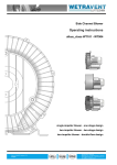
OPERATING INSTRUCTIONS
Two-speed Gearbox
2K800 / 2K801 / 2K802
08.2007 Edition
4161 758 103h
2K800/2K801/2K802
NOTE
These operating instructions also apply to the predecessor model 2K50.
Subject to alterations in design
Copyright by ZF
Reproduction, in whole or in part, is only allowed with our written approval and authorization.
Printed in Germany
Edition 08.2007
4161 758 103h
2
Operating Instructions
2K800/2K801/2K802
1
2
3
Contents
Preface.....................................................................................................................................................5
1.1
Safety instructions .........................................................................................................................5
1.2
ZF instructions ...............................................................................................................................5
1.3
Service products.............................................................................................................................6
Application and Design..........................................................................................................................7
2.1
Application ....................................................................................................................................7
2.2
Features..........................................................................................................................................7
2.3
Design ............................................................................................................................................8
2.4
Technical data ................................................................................................................................9
2.5
Installation positions ....................................................................................................................10
Initial Installation.................................................................................................................................11
3.1
Axial runout, radial runout and length tolerances – drive motor .................................................11
3.2 Balancing .....................................................................................................................................12
3.2.1 Semi-key balancing......................................................................................................................12
3.2.2 Full-key balancing .......................................................................................................................12
3.3
3.3.1
3.3.2
3.3.3
3.3.4
3.3.5
Adaptation, motor/gearbox ..........................................................................................................13
Open design .................................................................................................................................13
Close design (with shaft sealing ring)..........................................................................................14
Open design with adapter ring for 2K800 and 2K801 .................................................................15
Open design with adapter ring for 2K802....................................................................................15
Version with pulley drive ............................................................................................................16
3.4
Gearbox - fit.................................................................................................................................16
3.5 Output ..........................................................................................................................................17
3.5.1 Version with belt output ..............................................................................................................17
3.5.2 Version with coaxial output.........................................................................................................17
4
3.6
3.6.1
3.6.2
3.6.3
3.6.4
3.6.5
3.6.6
Electrical connection, gearchange ...............................................................................................18
Switching unit with solenoid unit ................................................................................................18
Switching unit with servo-motor .................................................................................................20
Switching logic for switching unit with solenoid unit .................................................................22
Switching logic for switching unit with solenoid unit and centre position..................................23
Switching logic for switching unit with servo-motor ..................................................................24
Switching logic for switching unit with servo-motor and centre position ...................................25
3.7
3.7.1
3.7.2
3.7.3
3.7.4
Lubrication...................................................................................................................................26
Recirculating lubrication..............................................................................................................26
Ports and connections for recirculating lubrication .....................................................................28
Gearbox oil pump (option) ..........................................................................................................29
Heat exchanger (option)...............................................................................................................31
Taking into Operation .........................................................................................................................33
4.1
Initial inspection ..........................................................................................................................33
3
Operating Instructions
Contents
5
Maintenance .........................................................................................................................................33
5.1
6
7
4
2K800/2K801/2K802
Oil change....................................................................................................................................33
Repair....................................................................................................................................................34
6.1
Gearbox fault checklist ................................................................................................................34
6.2
Gearbox - disassemble .................................................................................................................35
6.3
Hub ..............................................................................................................................................35
Frequently Asked Questions (FAQ) ...................................................................................................36
Operating Instructions
2K800/2K801/2K802
1
Preface
This documentation is intended for specialists who
have experience to carry out maintenance and
repair work.
The ZF product is documented in accordance with
the design status as of the issue date.
The following safety notices are used in these
operating instructions:
NOTE
Used to highlight special sequences, methods,
information, etc.
CAUTION
Used when incorrect and improper operating
procedures can cause damage to the product.
!
!
DANGER!
Used when due lack of care and attention
can cause injury to personnel and/or
damage to property.
ENVIRONMENTAL HAZARDS!
Lubricants and cleaning products must
not be poured onto the ground, into
groundwater or down the drain.
• Obtain and comply with the safety
regulations relevant to these products
issued by your local environmental
authority.
• Collect used oil in a suitably large
container.
• Dispose of used oil, clogged filters,
lubricants and cleaning products in
accordance with local environmental
protection regulations.
• Always follow the instructions issued
by the manufacturer when handling
lubricants and cleaning products.
Preface
1.1
Safety instructions
•
All persons repairing ZF units are responsible
for their own work safety.
•
Every applicable safety regulation and legal
requirement must be complied with in order to
prevent injury to personnel and/or damage to
the product during the course of maintenance
and repair work.
•
Repair staff should familiarize themselves with
these regulations before commencing work.
•
Correct and proper repair of these ZF products
can only be assured by appropriately trained
specialists.
•
The organization in charge of repairs is
responsible for ensuring that such training is
given.
•
Read these operating instructions carefully
before commencing any testing or repair work.
CAUTION
Pictures, drawings and components do not
always represent the original object but are
used to illustrate working procedures.
The illustrations, diagrams and parts are not
drawn to scale and no assumptions should be
made regarding size and weight (including
within a single illustration or drawing).
Work must be performed as described in the
text.
Following the completion of repair work and
testing, the specialists must satisfy themselves that
the product will function perfectly again.
1.2
ZF instructions
•
Remove any traces of old seals or gaskets from
mating faces. Use an oil stone to carefully
remove any burrs or similar irregularities.
•
Carefully cover or shield open gearboxes to
prevent the ingress of foreign matter.
5
Operating Instructions
Preface
1.3
2K800/2K801/2K802
Service products
Product
Grease
Name/specification
Shell Avania WR2
Quantity
(approx.)
[dm3]
Use
Remarks
General-purpose
Fuchs Renolit CXEP2
Esso Beacon EP2
Gearbox oil
HLP 46 to ISO VG 46
Gearbox oil
HLP 32 to ISO VG 32
6
Gearbox oil for
recirculating
lubrication
Gearbox oil for
recirculating
lubrication with
heat exchanger
Can also be used for
recirculating lubrication
with heat exchanger
Operating Instructions
2K800/2K801/2K802
2
2.1
Application and Design
Application and Design
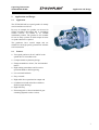
Application
The ZF-DUOPLAN two-speed gearbox is mainly
used in machine tool drives.
By way of example, the gearbox can be used in
turning machines (horizontal B5) or machining
centers (vertical V1) thanks to its variable
installation position. The gearbox is also suitable
for use in many systems in which torque increase
or speed reduction is required.
The gearboxes have coaxial output and are
suitable for the high speeds generated in machine
tool construction.
2.2
Features
•
Two-speed gearboxes for AC and DC main
spindle drives in machine tools
•
•
Compact thanks to planetary design
•
High running smoothness and low-noise
operation thanks to helical gearing
•
•
•
•
Low torsional backlash
•
•
High efficiency
Flange-mountable to all AC, DC and standard
motors
Easy to install
High radial forces permitted on output end
Combined axial and radial force thanks to
flexible output bearings
Electromagnetic or electromechanical gear
switching (depends on the version)
7
Operating Instructions
Application and Design
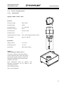
2.3
2K800/2K801/2K802
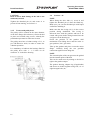
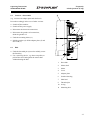
Design
The gearbox primarily comprises the following
assemblies:
Connecting parts
• Drive hub (1)
• Adapter plate (2) with radial shaft seal (3) and
hub bearings (4), as necessary
Housing
• Gearbox housing (5)
Input
• Sun gear (6)
• Ring gear (7)
• Ring gear bearings (8)
Output
• Bearing housing (9)
• Output bearings (10, 11)
• Output shaft (12)
• Radial shaft seal (13)
• Planet carrier (14)
• Axial bearing (15)
Shift mechanism
• Sliding sleeve (16)
• Shift fork (17)
• Brake disc (18)
Shift unit
• With servo-motor or solenoid unit (19)
027933
8
Operating Instructions
2K800/2K801/2K802
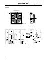
2.4
Application and Design
Technical data
Typ
2K800
2K801/802
Standard
version
2K800
2K801/802
with STW
(i=1.236)
Nominal power
max. 84 kW
max. 84 kW
Nominal speed
1000 rpm
1000 rpm
Max. speed
in direct drive i=1
5000 rpm
5000 rpm
NOTE
When using engine brakes/counterflow to brake
the spindles (e.g. emergency stop) ensure that the
moments of inertia do not exceed the admissible
output torques. Braking times must be adapted
accordingly.
Type
2K800
2K801/802
Standard
version
2K800
2K801/802
with STW
(i=1.236)
Nominal input max. 800 Nm
torque (S1)
max. 800 Nm
Max. output
torque (S1) for
i = 1.00
800 Nm
989 Nm
i = 3.19
2552 Nm
3154 Nm
i = 4.00
3200 Nm
3955 Nm
Weight
approx. 110 kg
approx. 325 kg
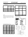
Model plate (standard)
(affixed to gearbox housing)
Standard fixing dimension (in mm)
in accordance with EN 50347: 2001
Two-speed
gearbox
2K800
FF350
2K801
FF400
2K802
FF500
Motor size
180
200
225
h
180
200
225
d
60
65
75
l
140± 0.2
140± 0.2
140± 0.2
b
300
350
450
e2
350
400
500
a1
400
450
550
s2
4x18.5
8x18.5
8x18.5
9
Operating Instructions
Application and Design
2.5
2K800/2K801/2K802
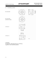
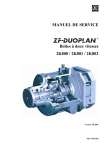
Installation positions
Horizontal B5
Horizontal B5
(shift unit rotated)
Vertical V1
Vertical V3
027929
CAUTION
The breather outlet must always be at the top,
regardless of the installation position.
10
Operating Instructions
2K800/2K801/2K802
3
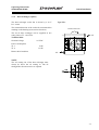
3.1
Initial Installation
Initial Installation
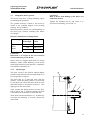
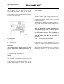
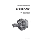
Axial runout, radial runout and length
tolerances – drive motor
In order to guarantee fault-free operation, the
motor must not exceed the specified tolerances.
A
B
C
L
001064
Axial runout, radial runout and length tolerances –
electric motor mounting flange:
Gearbox
type
2K800 /
2K801
2K802
Tolerance
A
B
C
L=140
0.030
0.063
0.063
± 0.200
A
B
C
L=140
0.030
0.063
0.063
± 0.200
Tolerances A, B, C to DIN 42955R
Please note that the tolerance of the shaft length "L" is
restricted in relation to the DIN standard
CAUTION
The special tolerance for shaft length "L" must
be maintained in order to guarantee fault-free
gearbox operation. Undersize shafts must be
compensated for by using shims when
mounting to the motor. Oversize shafts must be
machined to the correct length.
Take into account the motor shaft elongation
caused by heating in motors with fixed bearing on
the B-side (opposite the motor output shaft).
11
Operating Instructions
Initial Installation
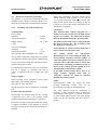
3.2
2K800/2K801/2K802
Balancing
The hubs (2) come with a keyway (1) for
transmitting power from the motor shaft (3) as
standard.
1
There are two balancing types for the motor and
gearbox: Semi-key and full-key, which are
described in more detail in DIN ISO 8821.
2
It must be ensured that the hub is balanced in the
same way as the motor.
3
This is why it is very important to indicate the
motor data, dimensions and balancing type when
ordering.
Motor output shafts with standard fitted key
in accordance with EN 50347: 2001
Gearbox
type
2K800
2K801
2K802
3.2.1
Shaft diameter
Fitted
key
Fitted key
length
60 mm
65 mm
75 mm
80 mm
A18x11
A18x11
A20x12
A22x14
110 mm
110 mm
125 mm
140 mm
Semi-key balancing
In semi-key balancing, the keyway is filled with a
balance
compensation
corresponding
to
approximately half a key, shape B by default. This
is based on the original key, shape, length and
position used by the motor manufacturer and is
defined as a counterweight. In semi-key balancing
– in contrast to full-key balancing – the joint
passes through a shared component. This means
imbalance can arise after assembly due to
tolerance factors.
As a result, it is recommended that rebalancing
should be performed after the joined parts have
been assembled.
3.2.2
Full-key balancing
In full-key balancing, the motor shaft is balanced
with a full key whereas the hub is not. The key,
shape, length and position are not important in
this case.
12
Semi-key balancing
Full-key balancing
Operating Instructions
2K800/2K801/2K802
3.3
Initial Installation
Adaptation, motor/gearbox
The motors must have a flange-mounting option
for mounting the gearboxes.
The gearbox housing is fitted to the motor by
means of the centering adapter on the bearing
housing. This is standard.
CAUTION
Risk of motor shaft damage if the hub is not
sufficiently heated.
Tighten the threaded pin (9) and secure it to
prevent it from turning, see section 3.4.
Different gearbox variants are used depending on
the motor type. Gearbox mounting also differs
accordingly.
Reference dimensions for hub position
Gearbox type
For output
shaft length
Dimension C
in mm
140
82.3 –0.2
140
148.3 –0.2
170
182.3 –0.2
2K800
2K801
2K802
CAUTION
Dimension C on request in the case of motors
with fixed bearing on the B-side.
Spacer discs are supplied with shims of varying
thickness. These enable balancing of the motor
shaft length tolerances and, therefore, compliance
with reference dimension "C".
3.3.1
Open design
The open version is the gearbox without adapter
plate but with seal on the motor output shaft (2) to
prevent gearbox oil ingress.
The drive hub (1) is delivered loose with the
gearbox. Clean the fitting surfaces of the motor
(3) and drive hub. Check the motor shaft for axial
and radial runout as described in section 3.1. Also
lightly grease the motor shaft.
After cleaning the fitting surfaces, heat the drive
hub to approx 120 °C from the opening and slide
it onto the motor shaft until it reaches the stop.
Then check reference dimension "C". If undersize,
use shims for balancing. If oversize, shorten the
motor shaft.
13
Operating Instructions
Initial Installation
3.3.2
Close design (with shaft sealing ring)
This variant incorporates an adapter plate (5) with
shaft seal (7), which means that the gearbox forms
a compact, closed unit.
The adapter plate (5) and drive hub (1) are
separately delivered loose. Clean the fitting
surfaces of the motor (3) and drive hub. Check the
motor shaft (2) for axial and radial runout as
described in section 3.1. Also lightly grease the
motor shaft (2).
After cleaning the fitting surfaces, place the
adapter plate with radial shaft seal (7) onto the
motor housing. Heat the drive hub to approx
120 °C from the opening and slide it onto the
motor shaft until it reaches the stop.
Then check reference dimension "C" and change
using shims if necessary.
CAUTION
Risk of motor shaft damage if the hub is not
sufficiently heated.
Tighten the threaded pin (9) and secure it to
prevent it from turning, see section 3.4.
CAUTION
Thoroughly grease the radial shaft seal and the
drive hub before installation. When installing,
make sure that the sealing lip and the radial
shaft seal are in the correct position.
NOTE
The radial shaft sealing ring in the drive motor
must be removed on the output end when the
closed design is used.
14
2K800/2K801/2K802
Operating Instructions
2K800/2K801/2K802
3.3.3
Initial Installation
Open design with adapter ring for
2K800 and 2K801
The adapter ring allows adaptation to different
connection dimensions. A seal is required on the
motor output shaft.
The adapter ring (5) and drive hub (1) are
delivered loose. Clean the fitting surfaces of the
motor (3) and drive hub (1). Check the motor
shaft (2) for axial and radial runout as described in
section 3.1. Also lightly grease the motor shaft.
After cleaning the fitting surfaces, place the
adapter ring onto the motor housing. Then heat
the drive hub to approx 120 °C from the opening
and slide it onto the motor shaft (2) until it
reaches the stop.
Then check reference dimension "C" and change
using shims if necessary.
CAUTION
Risk of motor shaft damage if the hub is not
sufficiently heated.
Tighten the threaded pin (9) and secure it to
prevent it from turning, see section 3.4.
3.3.4
Open design with adapter ring for
2K802
The adapter ring allows adaptation to different
connection dimensions. A seal is required on the
motor output shaft.
The adapter ring (5) and drive hub (1) are
delivered loose. Clean the fitting surfaces of the
motor (3) and drive hub (1). Check the motor
shaft (2) for axial and radial runout as described in
section 3.1. Also lightly grease the motor shaft
(2).
After cleaning the fitting surfaces, place the
adapter ring onto the motor housing. Then heat
the drive hub to approx 120 °C from the opening
and slide it onto the motor shaft (2) until it
reaches the stop.
Then check reference dimension "C" and change
using shims if necessary.
15
Operating Instructions
Initial Installation
2K800/2K801/2K802
CAUTION
Risk of motor shaft damage if the hub is not
sufficiently heated.
Tighten the threaded pin (9) and secure it to
prevent it from turning, see section 3.4.
3.3.5
Version with pulley drive
The pulley will be centred on the outer diameter
of the drive flange (K6 tolerance), friction-locked
in place and secured using screws, whereby the
permitted torque must be taken into account.
The pulley must have a balance rating of 6.3, as
per VDI Directive 2060, in order to ensure low
vibration operation.
It is mandatory to lubricate the bearings fitted in
the pulley drive with 1 – 1.5 l/min via oil
connector ‘S’ in the drive housing.
3.4
Gearbox - fit
NOTE
When fitting the drive hub (1), screw in and
tighten the threaded pin (9) onto the fitted key.
Make sure you coat the threaded pin with liquid
seal before installing it.
Make sure that the O-ring (10) is in the correct
position during installation. The O-ring is
delivered loose with the gearbox and has to be
coated with grease before being inserted into the
seal groove in the housing (6).
Check the position of the gearbox shift
mechanism. The sliding sleeve must be in the 1st
gear position ("low" gear ratio).
Take up the gearbox and place it onto the motor
flange. Carefully bring the sun gear/hub
connection together when doing this.
NOTE
The external spline of the sun gear must be guided
into the internal spline of the hub.
This can be made easier by turning to the left or
right at the gearbox output.
The gearbox housing, adapter ring (if applicable)
and motor are bolted together using four, six or
eight hexagon bolts (11).
028978
16
Operating Instructions
2K800/2K801/2K802
Initial Installation
Fill the gearbox with oil and connect up the
recirculating lubrication system and the power
supply. The breather outlet must always be at the
top, regardless of the installation position. Tighten
by max. 1 turn if necessary.
The gearbox is now ready for use.
3.5
3.5.1
Output
Version with belt output
The belt pulley must be centered on the outer
diameter of the output flange (tolerance K6),
fastened with the bolts so that it is frictionally
engaged and secured. Comply with the specified
tightening torques.
The belt pulley should be balanced to quality 6.3
as per VDI Directive 2060 in order to ensure lowvibration operation.
027928
CAUTION
Note the maximum specified tensioning force
when tightening the belts in order to prevent
bearing overload. The average belt force must
be between the bearings. When assembling, it
must be possible to easily slide the belt pulley
onto the output shaft. Heat the belt pulley if
necessary.
1st gear position
3.5.2
A
B
In the case of the version with coaxial output
(shaft stub), also note the balancing type for the
output (see section 3.2). The gearbox is delivered
with full-key balancing.
Brake disc
Sliding sleeve
CAUTION
The gearboxes can be operated under the same
degrees of protection as those defined for AC
and DC motors.
Version with coaxial output
Refer to the installation drawing for the fitted key
dimensions. Always fix the fitted keys using
threaded pins.
When setting up, make sure that the motor cooling
air can flow in and out unhindered.
NOTE
Before taking the electric motor/gearbox assembly
into operation, check that the gearbox output can
be turned by hand.
In the case of drive units that are fixed on the
gearbox flange, support the motor on the B-side
so that it does not vibrate.
17
Operating Instructions
Initial Installation
3.6
2K800/2K801/2K802
Electrical connection, gearchange
The gearbox is electrically connected using the
supplied 8-pole Harting connector (HAN 8 U).
The plug-in connection is located on the shift unit.
3.6.1
Switching unit with solenoid unit
Technical data:
Power rating
Standard
with neutral position
Supply voltage
± 10%
Current consumption
Standard
with neutral position
120 W
144 W
CAUTION
The solenoid must remain energized for a
further 0.5 to 1.0 seconds once the limit switch
signals are reached. The limit switch signals
must be monitored during the operating time.
24 V DC
The limit switches must only be energized with
the control current (0,1 - 0.5 A) and not with
the changeover current (6 A).
5A
6.0 A
If the number of resisters rather small, also a
lower control current can be used.
The required cable lead diameter is 1.5 mm².
The 24 VDC connection voltage and 5/6 A power
consumption must be assured at the solenoid plug.
Losses due to cable length and transition resistors
must be taken into account.
If switching the solenoid by relay, we recommend
you use a varistor, e.g. Siemens type S14-30
(30 V), to connect to the 24 V voltage, pin 2 and
pin 3.
Scope of supply:
Sleeve housing, screw connection, socket insert
and 8 jacks, type Harting AWG16
(ZF order no. 4161 298 004).
The shift unit can only be obtained as a complete
part.
Gearbox shift mechanism:
Gearchanges are effected when the 24 V voltage
is applied to pin 2 and 3. The polarity of the
applied voltage dictates which gear is engaged.
Solenoid L3 is always energized when the voltage
is applied, regardless of the polarity. It releases
the gear lock-out device before the gearchange is
effected.
18
During the gearchange, the main spindle motor
should make the shaft oscillate +5° at a rate of
1 to 5 rotation direction changes per second. The
limit switch signals from S1 (contact 4) and S2
(contact 6) serve to shut off the solenoid once the
gearchange is complete.
The control current for end-position
monitoring is to be set according to length, line
and transition resistance and the number of
connection points. Increased resistance due to
corrosion after some time must be taken into
consideration. Switching of inductive loads by
means of the control current requires it to be
wired parallel to the load by a diode.
If the limit switches detect that a gear is no
longer securely engaged, steps such as
emergency shut-off etc. must be initiated
through the control system.
NOTE
Electromagnetic fields can falsify the limit
position monitoring currents. This can be
prevented by re-routing or shielding the line.
The shift sequence must be monitored. If
necessary, a timer should be used to cancel the
shift sequence after approx. 2 seconds if there is
no limit switch signal (S1/S2). The main spindle
motor can not be operated until this signal is
present.
Operating Instructions
2K800/2K801/2K802
Initial Installation
Circuit diagram for switchgear unit with
solenoid unit and two switch positions
(standard) or three switch positions (with
neutral position):
1st gear ==>
e.g. 4:1
2nd gear ==>
1:1
3rd gear ==>
Neutral position, idling
(option)
Solenoid L1
Solenoid L2
Solenoid L3
Shift to 1st gear
Shift to 2nd gear
Release of lock-out device before
gearchange
Shift to neutral position (option)
Solenoid L4
Solenoid L4 must be energized for shifts from 1st
gear to 2nd gear and vice versa. Solenoid L4 is
de-energized in the case of shifts to neutral.
NOTE
Neutral can only be engaged from 1st gear.
Immediately shut off the power at L1 or L2 as
soon as limit switch S3 receives the signal.
19
Operating Instructions
Initial Installation
3.6.2
2K800/2K801/2K802
Switching unit with servo-motor
Specifications:
Power rating
85W
Supply voltage
24V DC ± 10%
Current consumption
(max. starting current)
5A
A supply cable cross-section of 1.5 mm² is
required.
The gear switching unit’s plug must be connected
up to the 24V DC supply voltage and the 5A
current consumption circuit.
Cable length and transfer resistance losses must
be taken into consideration.
We recommend using a varistor, e.g. Siemens
S14-30 (30V), for the 24V connections to Pin 2
and Pin 3 if you are using relays to switch the
switching unit.
Package contains:
Grommets, screws, socket unit and 8 Harting
AWG16 contact sockets,
(ZF Order-No. 4161 298 004).
The switching unit is only available as a complete
unit.
Gear switching:
The main spindle motor must undergo an
oscillating movement at an angle of ± 5° with 1 5 rotational direction changes per second whilst
switching gear levels. However, the gear’s
switching gear-teeth normally mesh together
during the first rotational direction change. This
means that the actual switching time is approx.
300 - 400 ms. The mechanical gearing level
switching is carried out by a switching unit on the
gear that is driven by a DC motor (24V DC) or a
solenoid unit.
The gear switching components (axial movement,
toothed sliding collar) are positive locking
components.
20
The switching positions are monitored by stop
switches inside the switching unit. A time relay
has been provided for monitoring the time lapse
that, if necessary, will reset the process if the
switching process has not been completed within
2 seconds after the switching process started (i.e.
if a signal has not been received from stop switch
S1 or S2). A new switching process must be
initiated afterwards. A time limit of 10 seconds
has been implemented for approx. 4 - 5 further
switching attempts. The system must be checked
out if the gearing has not switched over within
this time. Check the oscillating movement angle
and number of rotational direction changes and in
the majority of cases a smaller value must be set
and the switching process can be repeated
afterwards. (The gearing level switching sequence
plan can be found in Chapters 3.6.3 / 3.6.4 / 3.6.5
/ 3.6.6).
CAUTION
The stop switch signal must always be
monitored whilst the system is running.
The stop switch must be supplied with control
current (max. 0.5A) only and not with the
switching current (5A).
The switching sequence must be monitored and
the switching process must be reset by a timing
relay after approx. 2 seconds, if necessary, if the
stop switch does not generate a signal (S1/S2).
The main spindle motor must not be released by
the new switching command afterwards.
Operating Instructions
2K800/2K801/2K802
Initial Installation
Circuit diagram for a switching unit with three
switch positions (with neutral position):
1st Gear ==>
e.g. 4:1
2nd Gear ==>
1:1
3rd Gear ==>
neutral switch position,
idle running
(option)
The gearing is connected up electrically using the
8-pin Harting plug (HAN 8 U) supplied by us.
The plug connection is on the switching unit (with
neutral position):
027931
027932
21
Operating Instructions
Initial Installation
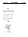
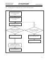
3.6.3
2K800/2K801/2K802
Switching logic for switching unit with solenoid unit
Reduce main spindle motor speed
from operating speed to zero.
Leave controller enable on
converter.
Apply desired oscillating speed to
converter and speed controller
without delay. 1)
Solenoid energized
(pin 2 and 3)
Gear ratio change is
completed within 2 seconds.
(Acknowledgement from limit
switch S1 or S2 from the shift unit)
Y
Shut off desired oscillating speed.
Solenoid OFF after 0.5 to 1.0
seconds
N
N
Number of attempted
shifts > 5 each from the
starting position
(polarity reversal)
Y
Gear ratio change not successful:
Switch off main spindle motor.
Check system.
Gear ratio change complete.
Main spindle motor start
after min. 0.5 seconds.
1) Alternatively, the first switching test can be performed without oscillating, but this requires a de-energized main spindle motor or minor outputend masses.
22
Operating Instructions
2K800/2K801/2K802
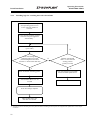
3.6.4
Initial Installation
Switching logic for switching unit with solenoid unit and centre position
Reduce main spindle motor speed
from operating speed to zero.
Leave controller enable on
converter.
Apply desired oscillating speed to
converter and speed controller
without delay. 1)
The solenoid unit is powered
when switching from gear 1
<--> gear 2
The lifting magnet is
powered (pin 1, 2, 3 and 8)
Switching to the neutral
position is only possible from
gear 1. The lifting magnet is
powered (pin 2 and 3)
Pin 1 and 8 de-energized
Gear level switching is completed
within 2 seconds (ready signal from
stop switch S1, S2 or. S3 in the
switching unit)
Y
Shut off desired oscillating speed.
Solenoid OFF after 0.5 to 1.0
seconds
N
N
Number of attempted
shifts > 5 each from the
starting position
(polarity reversal)
Y
Gear ratio change not successful:
Switch off main spindle motor.
Check system.
Gear ratio change complete.
Main spindle motor start
after min. 0.5 seconds.
1) Alternatively, the first switching test can be performed without oscillating, but this requires a de-energized main spindle motor or minor outputend masses.
23
Operating Instructions
Initial Installation
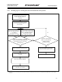
3.6.5
2K800/2K801/2K802
Switching logic for switching unit with servo-motor
Reduce main spindle motor speed
from operating speed to zero.
Leave controller enable on
converter.
Apply desired oscillating speed to
converter and speed controller
without delay. 1)
Servomotor for gear ratio
change ON (pin 2 and 3)
Gear ratio change is
completed within 2 seconds.
(Acknowledgement from limit
switch S1 or S2 from the shift unit)
Y
Shut off desired oscillating speed.
Servo motor OFF after 0.5 to 1.0
seconds
N
N
Number of attempted
shifts > 5 each from the
starting position
(polarity reversal)
Y
Gear ratio change not successful:
Switch off main spindle motor.
Check system.
Gear ratio change complete.
Start main spindle motor
1) Alternatively, the first switching test can be performed without oscillating, but this requires a de-energized main spindle motor or minor outputend masses.
24
Operating Instructions
2K800/2K801/2K802
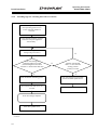
3.6.6
Initial Installation
Switching logic for switching unit with servo-motor and centre position
Reduce main spindle motor speed
from operating speed to zero.
Leave controller enable on
converter.
Apply desired oscillating speed to
converter and speed controller
without delay. 1)
Servomotor for gear ratio
change ON (pin 2 and 3)
Gearing level switching is
terminated in the neutral position by
a ready signal from S3.
(servo-motor short circuit)
Y
Shut off desired oscillating speed.
N
N
Number of switching attempts >5
for the given output length
(polarity reversal)
Y
Gear ratio change not successful:
Switch off main spindle motor.
Check system.
Gearing level switching is
terminated in the neutral position.
Centre position is polled via Pins 5
d7
Start main spindle motor
25
Operating Instructions
Initial Installation
3.7
Lubrication
3.7.1
Recirculating lubrication
NOTE
The 2K800, 2K801 and 2K802 gearboxes must
always be operated with recirculating lubrication.
In this case, the oil level is not visible in the oil
sight glass.
2K800/2K801/2K802
The following instances are no cause for concern:
• The oil level in the tank falls due to foaming of
the gearbox oil in the gearbox during
operation.
• An oil-air emulsion is formed in the oil return
and in the tank.
3.7.1.1
Recirculating lubrication for V1/B5
operation
CAUTION
Before operation for the first time, ensure that
the gearbox oil supply is taken into operation
first. To do this, check the oil level in the
reservoir and, if necessary, top up with oil until
the oil level is no longer below the minimum
mark in the reservoir.
Refer to section 3.7.2 for the position of the oil
inlets and outlets.
The pump, oil tank and heat exchanger
components must be arranged below the
gearbox oil level. The transmission oil supply
flow must be monitored.
If the gearbox is installed in vertical position V3,
the gearbox oil can be supplied both radially and
centrally.
NOTE
After switching off the machine, check that the oil
level in the reservoir does not rise above the
maximum mark.
The centrifugal forces acting on the oil can lead to
insufficient lubrication of the gearing during
continuous direct-drive operation.
Occasionally changing gear (ratio) and then
starting the motor (nMot=1000 rpm) supplies oil to
the gearing and prevents one-sided, positionspecific loading of the gearing.
Some applications require a very low operating
temperature level which can be reached by
connecting an adapted gearbox oil supply with oil
cooling. The respective gearbox versions are
prepared accordingly.
The gearbox has different ports and connections
for recirculating lubrication – depending on the
installation position and the operating type – in
order to ensure optimum gearbox cooling without
affecting lubrication.
The diagrams on page 22 show the oil inlet and
outlet points on the gearbox. Please refer to the
relevant installation drawings for precise details.
26
Oil inlet quantity:
Inlet 1: 2.5 l/min.
Inlet 2: 0.5 l/min.
The outlet line should be dimensioned so as to
prevent oil return blockages in the gearbox
(Di approx. 20 mm)
3.7.1.2
Recirculating lubrication with heat
exchanger
A heat exchanger is installed in the recirculating
lubrication system to ensure additional
temperature reduction.
Operating Instructions
2K800/2K801/2K802
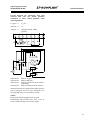
3.7.1.3
Initial Installation
Recirculating lubrication with
intermediate tank
Installation example B5
The tank volume should be at least ten times the
recirculating oil quantity in order to ensure
effective oil cooling.
NOTE
To prevent gearbox damage due to lack of oil, ZF
recommends you install an oil level sensor at the
intermediate tank.
A 60 µm filter must be used at the gearbox oil
inlet.
Option:
Tank with larger volume
(see chap. 3.7.4)
027930
27
Operating Instructions
Initial Installation
3.7.2
2K800/2K801/2K802
Ports and connections for recirculating lubrication
028049
Installation position
B5
Oil inlet port
M
0.5 l/min
Max. pressure
Oil return port
G or F
3 bar
or
K
2.5 l/min
V1
V3
5 bar
D or E
M
0.5 l/min
3 bar
K
2.5 l/min
5 bar
M
0.5 l/min
K
2.5 l/min
or
L (with suction)
H and I (with suction)
3 bar
5 bar
or
or
M
0.5 l/min
P
2.5 l/min
D
3 bar
G or F
5 bar
NOTE
The principal factor in determining the oil supply volume is always the volume that flows out of the oil return.
28
Operating Instructions
2K800/2K801/2K802
3.7.3
3.7.3.1
Initial Installation
Gearbox oil pump (option)
Specifications
Supply volume 3.4 dm3 / min.
Electrics:
Nominal voltage:
400V 50 Hz
Nominal rating:
100W
Operating mode:
S1 = 100% ED
Protection category:
IP 44
Nominal speed:
2 850 revs/min
Insulation class:
F
Thermal protection contact:
160°C when integrated and executed
Cable length:
approx. 1 000 mm
Hydraulics:
Supply volume:
1.21 cm³/U
Nominal pressure:
> 6.5 bar
Intake filter:
Filter mesh: 100 µm
Option:
Tank with larger volume (19 Ltr.)
The plastic container on the pump must be
removed when the tank is used. The pump is
then inserted together with the O-ring in the
appropriate opening and secured by means
of M8x35 cap screws.
More information about the products and
functional descriptions can be found in the
operating instructions
4161 758 005 (German)
4161 758 105 (English)
29
Operating Instructions
Initial Installation
3.7.3.2
2K800/2K801/2K802
Connection for nominal voltage 100-120 V AC
Terminal diagram 100 – 120 V AC:
Termin
L
N
PE
Jumpers
Circuit diagram for 100 – 120 V AC:
Capacitor CB
al
U1
Low
voltage
•
•
U2
U5
•
U6
•
Z1
Z2
11
Temperature monitoring
12
•
PE
Protective conductor
Connections 11 and 12 are for monitoring the temperature
of the pump motor.
3.7.3.3
Connection for nominal voltage 200-240 V AC
Terminal diagram 200-240 V AC:
Termin
L
N
PE
Jumpers
Circuit diagram for 200-240 V AC:
Capacitor CB
al
U1
•
•
U2
U5
U6
•
•
Z1
Z2
11
Temperature monitoring
12
PE
•
Protective conductor
Connections 11 and 12 are for monitoring the
temperature of the pump motor.
30
High
voltage
Operating Instructions
2K800/2K801/2K802
3.7.4
Initial Installation
Heat exchanger (option)
The heat exchanger cooler fan is driven by a 24 V
D.C. motor.
Type TL 1
The rotation direction of the cooler fan must match the
marking on the housing (note suction direction).
Rotation direction
The air-oil heat exchanger can be supplied in two
rating classes, TL 1 and TL 4.
Oil
Technical data:
Nominal voltage
Power consumption
TL 1
TL 4
24 V DC
41 W
113 W
Blower drive brushless
Oil
NOTE
The oil coming out of the heat exchanger must
always be above the oil coming in. The oil
through-flow direction can be as required.
AIR
31
Operating Instructions
Initial Installation
2K800/2K801/2K802
Type TL 4
Rotation direction
Oil
Air
Oil
Circuit diagram:
Customer side
32
Blower-side interface
Operating Instructions
2K800/2K801/2K802
4
4.1
Taking into Operation
Initial inspection
Check that the gearbox is correctly installed
before taking it into operation.
•
•
•
•
•
•
•
Taking into Operation/Maintenance
5
5.1
Gearbox oil ports and connections
Oil supply/oil fill assured
Electrical connections
Ease of movement (can be turned by hand)
Breather vertical position
Oil change
Oil change interval: Every 5000 operating
hours
Mechanical fastening
Motor flange-mounting
Maintenance
!
ENVIRONMENTAL HAZARD!
Lubricants and cleaning agents must not
be allowed to enter the ground, the water
table or the sewage system.
• Request safety information for the
products concerned from your local
environmental protection authority
and follow any instructions herein at
all times.
• Always collect used oil in a suitably
large container.
• Always dispose of used oil, clogged
filters, lubricants and cleaning agents
in accordance with environmental
protection laws.
• Always
observe
manufacturer
instructions when dealing with
lubricants and cleaning agents.
Drain used gearbox oil into a suitable container if
it is at operating temperature.
The drain ports differ depending on the
installation position and gearbox version (see
section 3.7.2).
Pour new gearbox oil through port I.
The oil level itself is all important. The oil
quantity in liters indicated on the model plate is a
reference value only.
If available, let the oil pump operate briefly after
filling with oil to remove any air and top up with
oil again if necessary.
33
Operating Instructions
Repair
6
2K800/2K801/2K802
Repair
Questions for fault diagnosis:
In the event of gearbox malfunctions, first check
the connected components and their ports and
connections.
•
Is gearbox oil sight glass dark/discolored
black?
•
Smell of burning oil at oil breather?
Carefully document the type of fault so as to assist
manufacturer diagnosis (see section 6.1).
•
Repairs on the gearbox itself may only be carried
out by ZF Friedrichshafen AG or by authorized
ZF after-sales points.
Gearbox running noise in 1:1 or 4:1 gear
ratio, or only in one rotation direction or in
both rotation directions?
•
Before the running noise occurred, was the
machine operated in only one gear ratio (1:1)
for an extended period of time?
6.1
•
Did the running noise occur after changing
the machine's cycle or was the machine cycle
unchanged?
•
Was any maintenance carried out on the
machine before the fault occurred and, if yes,
what did this maintenance work involve?
•
No gear change or gear loss in the event of a
shift problem?
•
Does shift logic conform to ZF specifications
(see page 22-25)?
•
What is the solenoid voltage during the shift
sequence?
Gearbox fault checklist
If you encounter drive unit faults, please refer to
the remedies in section 7 first of all for help.
If this does not solve the problem, you will need
to provide the following information for diagnosis
at ZF Friedrichshafen AG or an authorized ZF
after-sales point:
Gearbox data on the model plate:
Typ:
(Type)
Stückliste:
(Parts list no.)
Serien-Nr.:
(Serial no.)
...
.... ... ...
... ...
Motor data on the model plate
Manufacturer:
...
Type/size:
...
34
Operating Instructions
Frequently
2K800/2K801/2K802
6.2
Asked Questions (FAQ)
Gearbox - disassemble
(e.g. version with adapter plate and shaft seal)
Proceed accordingly in the case of other versions.
•
•
•
•
Switch off the machine
•
•
Undo the mounting bolts (11)
6.3
Switch off the power supply
Disconnect the electrical connections
Disconnect the gearbox oil connections,
drain the gearbox oil
Pull the gearbox (6) off the adapter plate (5) and
drive hub (1)
Hub
•
Undo the threaded pin (9) used to radially secure
the fitted key
•
Use a removing device, e.g. three-arm puller, to
pull off the drive hub against the motor shaft
without heating the hub.
1
Drive hub
2
Motor shaft
3
Motor
4
Cover
5
Adapter plate
6
Gearbox housing
7
Shaft seal
9
Threaded pin
10 O-ring
11 Mounting bolt
35
Frequently
Operating Instructions
Asked Questions (FAQ)
7
2K800/2K801/2K802
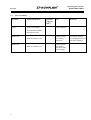
Frequently Asked Questions (FAQ)
Error
Cause of error
Remedy
Gearbox is loud, knocking
noises
• Loose contact on motor speed
sensor, which causes permanent
motor governing.
Check speed sensor and electrical
lines to motor, clean speed sensor if
necessary.
• Speed sensor dirty, no clear
signals sent.
Check engine management system,
adjust speed control accordingly
(softer setting).
Long periods at high cutting speed
in ratio 1:1 followed by change to
machining in ratio 4:1.
No gearbox damage.
Gearbox is loud, running noise
in ratio
Motor shaft is too long,
axial bearing damaged
Check bearing,
install new bearing if necessary
Gearbox leaking at gearbox
input/output.
Defective seals.
Renew seals, send gearbox to ZF
for inspection if necessary.
Gearbox leaking at breather
• Oil has aged.
• Change the oil.
• Too much oil added during oil
change.
• Check the oil level and correct if
necessary.
• Loose contact in the plug
connection on the gearbox shift
unit.
• Check the plug connection and
clean if necessary, secure
connectors using clips.
• Error in the shift unit.
• Send gearbox to ZF for
inspection.
Gearbox is loud, running noise.
Machine control receives no
shift position signals from the
gearbox shift unit.
Gear disengages
36
• Limit position switch defective
Gearbox running noise normalizes
after several gear changes.
• Send gearbox to ZF
Friedrichshafen AG for
inspection
Operating Instructions
2K800/2K801/2K802
Frequently
Asked Questions (FAQ)
37
ZF Friedrichshafen AG
Sonder-Antriebstechnik
Ehlersstraße 50 • D-88046 Friedrichshafen
Phone: ++49 (75 41) 77-0 • Fax: ++49 (75 41) 77-34 70
E-mail: [email protected] • Internet: www.zf.com