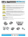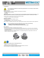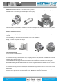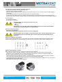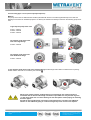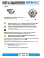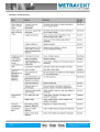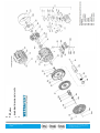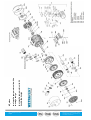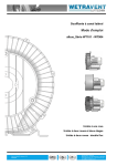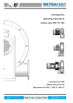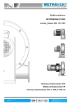
1
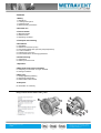
Side Channel Blower
Operating instructions
albus_class WT101 - WT904
single-impeller blower - one stage design
two-impeller blower - two-stage design
two-impeller blower - double-flow design
BA_Nr.: BAWT2 Version V2.0
English
WETRAVENT Lufttechnik
Albstrasse 10 D-73765 Neuhausen - Germany
[email protected] I www.wetravent.com
Tel: 0049 (0) 7158-98 775-97
Contents
1 Safety
1.1 Definitions
1.1.1 Safety alert symbol
1.1.2 Signal words
1.2 General safety precautions
2 Intended use
3 Technical data
3.1 Mechanical data
3.2 Electrical data
3.3 Operating conditions
4 Transport and handling
5 Installation
5.1 Installation
5.2 Electrical connection (motor)
5.3 Connecting pipes/hoses (vacuum pump/compressor)
5.3.1 Inlet connection
5.3.2 Discharge connection
5.3.3 Procedure when connecting pipes/hoses
6 Commissioning
6.1 Preparation
6.2 Start-up and shut-down
7 Operation
8 Shut-down and longer standstills
8.1 Preparing for shut-down or longer standstill
8.2 Storage conditions
9 Servicing
9.1 Emptying/Rinsing/Cleaning
9.2 Repairs/troubleshooting
9.3 Service/After-sales service
10 Disposal
EU declaration of conformity
Design of Side channel blower albus_class
BA_Nr.: BAWT2 Version V2.0
English
WETRAVENT Lufttechnik
Albstrasse 10 D-73765 Neuhausen - Germany
[email protected] I www.wetravent.com
Tel: 0049 (0) 7158-98 775-97
1 Safety
1.1 Definitions
To point out dangers and important information, the following signal words and symbols are used in these operating
instructions:
1.1.1 Safety alert symbol
The safety alert symbol is located in the safety precautions in the highlighted heading field on the left next
to the signal word (DANGER, WARNING, CAUTION).
Safety precautions with a safety alert symbol indicate a danger of injuries.
Be sure to follow these safety precautions to protect against injuries or death!
Safety precautions without a safety alert symbol indicate a danger of damage.
1.1.2 Signal words
DANGER
WARNING
NOTICE
Danger of injuries. Indicates an imminently hazardous situation, that will result in death or
serious injury if the corresponding measures are not taken.
Danger of injuries. Indicates a potentially hazardous situation, which could result in death or
serious injury if the corresponding measures are not taken.
Danger of injuries. Indicates a potentially hazardous situation, which may result in minor or
moderate injury if the corresponding measures are not taken.
Danger of damage. Indicates a potentially hazardous situation, which may result in property
damage if the corresponding measures are not taken.
Indicates a possible disadvantage, i.e. undesirable conditions or consequences can occur if the
corresponding measures are not taken.
Indicates possible advantages if the corresponding measures are taken; tip.
BA_Nr.: BAWT2 Version V2.0
English
WETRAVENT Lufttechnik
Albstrasse 10 D-73765 Neuhausen - Germany
[email protected] I www.wetravent.com
Tel: 0049 (0) 7158-98 775-97
1.2 General safety precautions
Improper use of the unit can result in serious or even fatal injuries! All work on and with the pumpmotor unit (transport, installation, operation, shut-down, maintenance, disposal) may only be carried
out by trained, reliable expert personnel!
When working on the unit, there is a danger of injury, e.g. in the form of cuts/cutting off,
crushing and burns! During all work on and with the pump-motor unit (transport, installation,
operation, shut-down, maintenance, disposal) wear personal safety equipment (safety helmet,
protective gloves, safety shoes)!
Hair and clothing can be pulled into the unit or caught and wound up moving parts! Do not
wear long, loose hair or wide, loose clothes! Use a hair net!
Electrical danger! Work on electrical installations may be carried out by trained and
authorized electricians only!
Electrical danger!
Before beginning work on the unit or system, the following measures must be carried out:
Deenergize.
Secure against being switched on again.
Determine whether deenergized.
Ground and short-circuit.
Cover or block off adjacent energized parts.
Electrical danger!
Do not open the motor terminal box until absence of electricity has been ensured!
Danger due to vacuum and gauge pressure:
sudden escape of fluids (skin and eye injuries), sudden drawing in of hair and clothing!
Danger due to escaping fluid: Burns! Use mounting elements, connections, lines, fittings and
containers with sufficient freedom from leaks and strength for the pressures which occur.
Check the mounting elements, connections, lines, fittings and containers for strength, leaks
and firm seating at regular intervals!
Danger from rotating parts (external fan, impeller, shaft): Cutting/cutting off of extremities,
Grasping/winding up of hair and clothing!
Danger due to vacuum and gauge pressure: sudden escape of fluids (skin and eye injuries),
sudden drawing in of hair and clothing! Danger due to escaping fluid: Burns!
Start-up and operation only under the following conditions:
The pipes/hoses must be connected to inlet and discharge connections.
Inlet and discharge connections and the connected pipes/hoses may not be closed,
clogged or soiled.
Check the mounting elements, connections of the pipe/hose connections, lines, fittings
and containers for strength, leaks and firm seating at regular intervals!
Danger from rotating impeller: Cutting/cutting of off extremities!
The rotating impeller is accessible with the inlet and discharge connections open!
With free entry and exit of gases, i.e. with direct intake out of or direct feeding into the
atmosphere without piping, the following therefore applies:
Provide the inlet and discharge connections of the pump-motor unit either with additional
mufflers or with additional piping of a sufficient length to prevent access to the impeller!
Danger of burns from hot surfaces of the pump-motor unit and from hot fluids!
High temperatures of up to approx. 160°C [320°F] can occur on the surface of the pumpmotor
unit. Cover the pump-motor unit with a suitable touch protection (e.g. perforated plate cover
or wire cover). Do not touch during operation! Allow to cool after shut-down!
BA_Nr.: BAWT2 Version V2.0
English
WETRAVENT Lufttechnik
Albstrasse 10 D-73765 Neuhausen - Germany
[email protected] I www.wetravent.com
Tel: 0049 (0) 7158-98 775-97
2 Intended use
This operating manual
is intended for side channel compressors of the albus class, WT_series (WT_albus),
contains instructions bearing on transport and handling, installation, commissioning, operation, shut-down, storage,
servicing and disposal of the WT_albus,
must be completely read and understood by all operating and servicing personnel before beginning to work with or on
the WT_albus,
must be strictly observed,
must be available at the site of operation of the WT_albus.
About the operating and servicing personnel of the WT_albus
These persons must be trained and authorized for the work to be carried out.
Work on electrical installations may be carried out by trained and authorized electricians only.
The WT_albus
are pump-motor units for generating vacuum or gauge pressure;
are used to extract, pump and compress the following gases:
– Air,
– Non-flammable, non-aggressive, non-toxic and non-explosive gases or gas-air mixtures.
– With differing gases/gas-air mixtures, inquire with the Service Department.
are equipped with one of the following kind of drive motors:
– 3-phase AC drive motor with a standard design
– Single-phase AC drive motor
are intended for industrial applications,
are designed for continuous operation.
With increased switch-on frequency (6x per hour with equal pauses and operating times) or with increased gas inflow and
ambient temperature, the excess temperature limit of the coil and the bearing can be exceeded.
Consult WETRAVENT when using under such conditions.
Foreseeable misuse
to use the WT_albus in applications other than industrial applications unless the necessary protection is provided
on the system, e.g. guards suitable for children's fingers;
to use the device in rooms in which explosive gases can occur if the WT_albus is not expressly intended for this
purpose;
to extract, to deliver and to compress explosive, flammable, corrosive or toxic fluids, unless the WT_albus is
specifically designed for this purpose;
Any unauthorized modifications of the WT_albus are prohibited for safety reasons.
The operator is only permitted to perform the maintenance and service work described in these operating instructions.
Maintenance and servicing work which goes beyond this may only be carried out by companies which have been
authorised by the manufacturer (ask the WETRAVENT service department for details).
BA_Nr.: BAWT2 Version V2.0
English
WETRAVENT Lufttechnik
Albstrasse 10 D-73765 Neuhausen - Germany
[email protected] I www.wetravent.com
Tel: 0049 (0) 7158-98 775-97
3 Technical data
3.1 Mechanical data
See rating plate.
Minimum distances:
Minimum distance to face of vacuum pump/compressor cover
Minimum distance to fan guard (for sucking in cooling air)
:
Type
WT1 – WT5
WT6 – WT8
WT9
[mm]
20
20
25
Type
WT1 – WT5
WT6
WT8 – WT9
[mm ]
40
50
60
:
3.2 Electrical data
See rating plate.
3.3 Operating conditions
Temperatures
Rating plate
Temperature of pumped gases:
max. permissible temperature: +45°C
Nominal value: +15°C
Temperature of pumped gases: Pump-motor units for higher fluid temperatures on request.
Ambient temperature:
max. permissible temperature: +40°C
min. permissible temperature:-20°C
Nominal value: +25°C
Ambient temperatures between 25°C and 40°C affect the permissible total pressure difference. At higher temperatures the
winding may be damaged and the grease change interval may be shortened.
Pressures
Permitted total pressure difference: See rating plate.
The total pressure difference, shown on the rating plate, applies only for the following conditions:
Ambient temperature: 25°C
Pressure for vacuum operation: 1013 mbar at pressure connection;
Pressure for compressor operation: 1013 mbar at suction connection;
Intake temperature (temperature of conveyed gases at suction connection): 20°C
For ambient temperatures between 25°C and 40°C, the total pressure difference specified on the rating plate must be
reduced (at 40°C by 10%).
Consultation with WETRAVENT is essential for such operational conditions. (www.wetravent.com).
Installation altitude: Max. of 1,000 m [3,280 ft] above sea level.
When installing the pump-motor unit at an altitude of more than 1,000 m [3,280 ft] above sea level, first inquire with the Service
department (www.wetravent.com).
BA_Nr.: BAWT2 Version V2.0
English
WETRAVENT Lufttechnik
Albstrasse 10 D-73765 Neuhausen - Germany
[email protected] I www.wetravent.com
Tel: 0049 (0) 7158-98 775-97
4 Transport and Handling
Tipping or falling can lead to crushing, broken bones etc.! Sharp edges can cause cuts!
Wear personal safety equipment (gloves, safety shoes and protective helmet) during transport!
Danger from tipping or falling loads!
Prior to transport and handling make sure that all components are securely assembled and secure or
remove all components the fasteners of which have been loosened!
The transport must be carried out in different ways depending on the type:
WT1 – WT5 (single-impeller): Manual handling
WT5. (two-impeller), WT6 – WT9: Transport with crane, hooked onto eye bolt/lifting attachment (1 attachment point).
Eye bolt/lifting attachment:
Types with a weight of up to 30 kg [66 lbs] are not equipped with an eye bolt/lifting attachment.
Types with a weight of more than 30 kg [66 lbs] are equipped with an eye bolt/lifting attachment as standard.
The eye bolt/lifting attachment is mounted on the vacuum pump/compressor housing.
In case of possible removal and remounting of the eye bolt, it must be ensured that the eye level is positioned exactly in
the axis direction of the pump-motor unit. Lay shims under the eye bolt if necessary.
The eye bolt/lifting attachment must be firmly tightened.
Loads laterally to the ring level are not permissible. Heavy impact loads during transport must be avoided.
Base plate just for transport purpose
BA_Nr.: BAWT2 Version V2.0
English
WETRAVENT Lufttechnik
Albstrasse 10 D-73765 Neuhausen - Germany
[email protected] I www.wetravent.com
Tel: 0049 (0) 7158-98 775-97
5 Installation
Electrical danger! The pump-motor unit must be installed so that the electrical device cannot be
damaged by external influences! In particular, the feed pipes must be securely routed, e.g. in cable
ducts, in the floor etc.
Danger from crushing due to pump-motor unit tipping over! Wear personal safety equipment
(protective gloves and safety shoes). Handle the unit with the appropriate care. Install the pumpmotor unit on a solid foundation or on a solid mounting surface! Check screw glands/unions for
mounting the pump-motor unit on the mounting surface regularly for strength.
Danger of fire from flammable substances! The pump-motor unit must never come into
contact with flammable substances.
Danger of burns from hot surfaces of the pump-motor unit and from hot fluids!
High temperatures of up to approx. 160°C [320°F] can occur on the surface of the pumpmotor unit.
The pump-motor unit must be installed so that accidental touch of its surface is not possible. Cover
the pump-motor unit with a suitable touch protection (e.g. perforated plate cover or wire cover).
Danger of injuries from flying parts! Select installations so that parts that are thrown out through the grate if the
external fan breaks cannot hit persons!
Danger of overheating due to hot surface of pump-motor unit! High temperatures can occur on
the surface of the pump-motor unit. Temperature sensitive parts, such as lines or electronic
components, may not come into contact with the surface of the pump-motor unit.
Carry out the following work to install the pump motor unit:
Installation and securing,
Attachment of the included loose muffler if necessary,
Attachment of threaded flange or hose flange (available as accessories) for the connection of inlet or discharge pipe to
the muffler,
Electrical connection,
Connection of inlet and discharge connection to the system.
BA_Nr.: BAWT2 Version V2.0
English
WETRAVENT Lufttechnik
Albstrasse 10 D-73765 Neuhausen - Germany
[email protected] I www.wetravent.com
Tel: 0049 (0) 7158-98 775-97
5.1 Installation
For an installation that differs from the following specifications, it is necessary to inquire with the
Service Department!
Ambient conditions:
The pump-motor unit is suitable for installation in the following environments:
In a dusty or damp environment,
in buildings,
in the open.
When properly installed in the open, the pump-motor unit must be protected from exposure to intensive sunlight, e.g. by
attaching a protective roof. Otherwise, no special protective devices against the effects of weathering are required.
The drive motors of the pump-motor units have the following design:
with degree of protection IP55 (see rating plate).
Installation conditions:
The pump-motor unit must be installed as follows:
on level surfaces,
at a maximum height of 1000 m [3280 ft] above sea level.
When installing at an altitude of more than 1,000 m [3,280 ft] above sea level, first inquire with the service department.
To ensure sufficient cooling of the pump-motor unit, also observe the following:
Ventilation screens and openings must remain clear.
Discharge air of other units may not be directly sucked in again!
Noise radiation:
To reduce the noise radiation, the following must be observed:
Do not mount pump-motor unit on noise conducting or noise-radiating parts (e.g. thin walls or sheet-metal plates).
Provide pump-motor unit with sound insulating intermediate layers (e.g. rubber buffers under the base of the pumpmotor unit) if necessary.
Install the pump-motor unit on a stable foundation or on a rigid mounting surface. This provides for smooth, lowvibration running of the pump-motor unit.
Components for reducing noise on the pump motor unit:
Mufflers (included as standard equipment):
On delivery the pump-motor units are equipped with attached mufflers as standard.
The noise radiation is considerably reduced by the mufflers.
BA_Nr.: BAWT2 Version V2.0
English
WETRAVENT Lufttechnik
Albstrasse 10 D-73765 Neuhausen - Germany
[email protected] I www.wetravent.com
Tel: 0049 (0) 7158-98 775-97
Additional silencer (available as an accessory for the WT_albus):
The additional mufflers enable a further noise reduction. They may only be used with free entry and exit of gases, i.e. with
direct intake out of or direct feeding into the atmosphere without piping.
Sound protection hood (available as an accessory for the WT_albus):
Noise protection hoods are suitable for installation in rooms and in the open. They reduce both the total sound pressure
level and tonal components that are perceived as particularly annoying.
Installation variants/axis position:
Basically, when installing the pump-motor unit, the following variants are possible with a different axis position (horizontal
or vertical):
Horizontal installation
Vertical installation on the vacuum pump/compressor cover ("cover installation")
Vertical mounting on the wall
Basically, all variants are possible with all type.
Horizontal axis mounting
The foot of the unit has fastening holes.
Screw the foot of the unit to the base using suitable screws. All fastening holes must have screws!
Vertical axis mounting on the compressor cover ("cover position")
For vertical axis mounting on the compressor cover, use spring elements. Spring elements are available as accessories
and come in a set of 3. The upper part has a threaded stud and the lower part a threaded hole.
Fastening spring elements to the unit:
Screw threaded studs of the spring elements into the holes on the front side of the compressor cover and tighten.
Fastening the unit with spring elements to the foundation:
Select suitable fastening elements for the threaded hole. Screw spring elements over the threaded hole into the base or
foundation.
Vertical axis mounting on the wall with the compressor covers pointing downward
For vertical axis mounting of the unit on the wall, the unit is fastened using the holes in the foot. The foot of the unit has
fastening holes.
Place the unit with the foot to the wall on a base plate with sufficient load-bearing capability in the mounting position.
Screw the foot of the unit to the wall using suitable screws. All fastening holes must have screws!
Remove the base plate.
BA_Nr.: BAWT2 Version V2.0
English
WETRAVENT Lufttechnik
Albstrasse 10 D-73765 Neuhausen - Germany
[email protected] I www.wetravent.com
Tel: 0049 (0) 7158-98 775-97
5.2 Electrical connection (motor)
Electrical danger! Malpractice can result in severe injuries and material damage!
Electrical danger! The electrical connection may be carried out by trained and authorized
electricians only!
Electrical danger! Before beginning work on the unit or system, the following measures must
be carried out:
Deenergize.
Secure against being switched on again.
Determine whether deenergized.
Ground and short-circuit.
Cover or block off adjacent energized parts
Incorrect connection of the motor can lead to serious damage to the unit!
Regulations:
The electrical connection must be carried out as follows:
according to the applicable national and local laws and regulations,
according to the applicable system-dependent prescriptions and requirements,
according to the applicable regulations of the utility company.
Electrical power supply:
Observe the rating plate. It is imperative that the operating conditions correspond to the data given on the rating plate!
Deviations permissible without reduction in performance:
±5 % voltage deviation
±2 % frequency deviation
Connection to drive-motor terminal box:
Open the required cable entry openings on the terminal box. Here the following two cases are differentiated:
The cable entry opening is prefabricated and provided with a sealing plug.
Screw out sealing plug.
OR
The cable entry opening is closed off with a casting skin.
Break out casting skin using a suitable tool. For example, use a metal pin with a corresponding diameter or a chisel and
hammer.
When pounding out the casting skin on the cable entry openings in the terminal box, the terminal
box or its parts can be damaged (e.g. terminal board, cable connections). Proceed with suitable
caution and precision when doing so! Prevent flash formation!
Mount cable glands on the terminal box. Proceed as follows:
Select one cable gland in each case which is suitable for the cable diameter.
Insert this cable gland in the opening of the terminal box. Use a reducer if necessary.
Screw on the cable gland so that no moisture, dirt etc. can penetrate into the terminal box.
Carry out the connection and the arrangement of the jumpers in accordance with the circuit diagram in the terminal
box.
Connect the protective conductor to the terminal with the following symbol:
BA_Nr.: BAWT2 Version V2.0
English
WETRAVENT Lufttechnik
Albstrasse 10 D-73765 Neuhausen - Germany
[email protected] I www.wetravent.com
Tel: 0049 (0) 7158-98 775-97
The electrical connection must be carried out as follows:
The electrical connection must be permanently safe.
There may be no protruding wire ends.
Clearance between bare live parts and between bare live parts and ground: ≥ 5.5 mm [0.217"] (at a nominal voltage of
UN ≤ 690V).
For the tightening torques for terminal board connections (except terminal strips).
For terminals with clamping straps, the conductors must be inserted so that approximately the same clamping height
results on both sides of the bar. Individual conductors must therefore be bent into a U-shape or connected with a cable lug.
This also applies to:
the protective conductor,
the outer ground conductor.
Electrical danger! The terminal box must be free from
foreign bodies,
dirt,
humidity.
Terminal box cover and cable entries must be tightly closed so as to make them dustproof
and waterproof. Check for tightness at regular intervals.
For motor overload protection:
Use motor circuit breakers.
This must be adjusted to the specified nominal current (see rating plate).
Electrical danger! There is danger of an electrical shock when a defective pump-motor unit is
touched! Mount motor circuit breaker. Have electrical equipment checked regularly by an
electrician.
Interference immunity of drive motor:
For drive motors with integrated sensors, the operator must provide for sufficient interference immunity itself. Select a
suitable sensor signal cable (e.g. with screening, connection as for a motor power-supply cable) and analyzing unit.
Operation with frequency converter:
With a power supply by a frequency converter, the following must be observed:
High-frequency current and voltage harmonics in the motor supply cables can lead to emitted electromagnetic
interference. This is dependent on the converter design (type, manufacturer, interference suppression measures).
Be sure to observe the EMC notes of the converter manufacturer!
Use screened power supply cables if necessary. For optimal screening, the screen must be conductively connected
over a large area to the metal terminal box of the drive motor with a screwed metal gland.
In the case of drive motors with integrated sensors (e.g. PTC thermistors) interference voltage can occur on the sensor
cable depending on the converter type.
Limit speed: see specifications on the rating plate.
BA_Nr.: BAWT2 Version V2.0
English
WETRAVENT Lufttechnik
Albstrasse 10 D-73765 Neuhausen - Germany
[email protected] I www.wetravent.com
Tel: 0049 (0) 7158-98 775-97
5.3 Connecting pipes / hoses (vacuum pump/compressor)
Mufflers:
The pump-motor units are delivered with mufflers (indicated with arrows in the following illustrations) for the inlet and
discharge connections as standard equipment. On delivery the mufflers are already mounted on the following pump-motor
units.
single-impeller pump-motor units
WT101 – WT901
WT409 – WT609
WT303 – WT603
two-impeller pump-motor units
with a two stage design
WT302 – WT902
X
two-impeller pump-motor unit
with double-flow design
WT504 – WT904
On two-impeller pump-motor units with a twostage design the discharge-side muffler is included loose for packingrelated reasons and must be mounted by the customer .
X
Danger from rotating impeller: Cutting/cutting of off extremities! The rotating impeller is
accessible with the inlet and discharge connections open! With free entry and exit of gases,
i.e. with direct intake out of or direct feeding into the atmosphere without piping, the following
therefore applies:
Provide the inlet and discharge connections of the pump-motor unit either with additional
mufflers or with additional piping of a sufficient length to prevent access to the impeller!
BA_Nr.: BAWT2 Version V2.0
English
WETRAVENT Lufttechnik
Albstrasse 10 D-73765 Neuhausen - Germany
[email protected] I www.wetravent.com
Tel: 0049 (0) 7158-98 775-97
Connections:
To prevent foreign bodies from entering the unit, all connections are sealed off when delivered. Do not remove the sealing
plugs until immediately before connecting the pipes/hoses.
The following applies for the arrangement of the pipe/hose connections:
The pumped gases are sucked in via the inlet connection and
discharged via the discharge connection .
The shaft rotating direction is marked with an arrow on the back of the vacuum pump/compressor housing
The delivery direction of the gases is marked with arrows on both connections .
.
Danger from interchanging inlet and pressure line! Interchanged inlet and pressure lines can lead to
damage to the pump-motor unit and the system, and as a result of this to serious injuries! Make sure
that the inlet and pressure line cannot be confused when connecting. Look for the clear marking
with the arrow indicating the delivery direction on the inlet and discharge connections.
Danger due to vacuum and gauge pressure! Danger due to escaping fluid! During operation,
connected pipes and vessels are vacuumized or pressurized! Use only mounting elements,
connections, lines, fittings and containers with sufficient freedom from leaks and strength for the
pressures which occur. Make sure that the mounting elements and connections are mounted
sufficiently firmly and leak-free!
Attach pipes/hoses free of mechanical tensions. Support the weight of the pipes/hoses.
5.3.1 Inlet connection
The inlet connection with the related muffler is marked with an arrow pointing into the vacuum pump /
compressor. Connect the inlet pipe here. The pumped gases are sucked in via this .
Danger from solid bodies and impurities in the pump-motor unit! If solid bodies penetrate into the
pump-motor unit, blades of the impellers can break and broken pieces can be thrown out.
Install a filter in the inlet pipe. Replace filter regularly!
5.3.2 Discharge connection
The discharge connection with the related muffler is marked with an arrow pointing out of the vacuum pump/compressor.
Connect the discharge pipe here. The pumped gases are discharged via this .
5.3.3 Procedure when connecting pipes/hoses
Attach the pipes/hoses to the unit as described in the following. The pipes/hoses are connected differently to inlet and
discharge connections depending on the muffler design and the type of line (pipe or hose):
Muffler with inside threads: The pipe is screwed directly into the muffler.
Muffler without inside thread:
– Screw threaded flange (available as an accessory) onto the muffler.
– Screw the pipe into the threaded flange.
Hose connection:
– screw the hose flange (available as an accessory) onto the silencer.
– Push the hose onto the hose flange and secure it with a hose clamp.
BA_Nr.: BAWT2 Version V2.0
English
WETRAVENT Lufttechnik
Albstrasse 10 D-73765 Neuhausen - Germany
[email protected] I www.wetravent.com
Tel: 0049 (0) 7158-98 775-97
6 Commissioning
6.1 Preparation
Danger from closed connections! With closed/soiled intake or discharge connections vacuum or
gauge pressure results in the pump-motor unit. This can overheat and damage the drive motor
winding. Before start-up, make sure that the inlet and discharge connections are not closed, clogged
or soiled!
Measures before start-up:
If a shut-off device is installed in the discharge pipe: Make sure that the unit is NOT operated with the shut-off device
closed.
Before starting up the pump-motor unit, observe the values specified on the rating plate. Specifications on the drivemotor nominal current apply at a gas entry and ambient temperature of +45° C.
Adjust the motor circuit breaker to the drive-motor nominal current.
Check direction of rotation:
The intended rotating direction of the shaft is marked with arrows on the vacuum pump/compressor housing .
The gas delivery direction is marked with arrows on the inlet and discharge connections
.
Make sure the pipes/hoses on the inlet and discharge connections are properly connected.
Switch the pump-motor unit on briefly and then off again.
Compare the actual rotating direction of the external fan with the intended shaft rotating direction indicated with the
arrows shortly before the pump-motor unit comes to a standstill.
If necessary, reverse the direction of rotation of the motor.
Electrical danger! The electrical connection may be carried out by trained and authorized
electricians only!
Electrical danger! Before beginning work on the unit or system, the following measures must be
carried out:
Deenergize.
Secure against being switched on again.
Determine whether deenergized.
Ground and short-circuit.
Cover or block off adjacent energized parts.
Check operating speeds:
Observe the operating speed specified on the rating plate. This may not be exceeded, as otherwise the noise radiation,
vibration behavior, grease consumption duration and bearing change interval worsen. To prevent damage as a result of
higher speeds, it may be necessary to inquire with the Service Department as to the maximum speed.
Danger of hearing damage due to noise radiation! However, the actual noise emission during
operation is highly dependent on the installation and system conditions. Conduct a noise
measurement in the system during operation after installing the pump-motor unit. The
following measures can be taken from 85 dB(A) and must be taken from 90 dB(A):
Mark noise area with a warning sign.
Wear hearing protection.
With free entry and exit of gases, i.e. with direct intake out of or direct feeding into the
atmosphere without piping, attach an additional muffler.
6.2 Start-up and shut-down
Start-up:
Open shut-off device in intake/discharge pipe.
Switch on power supply for drive motor.
Shut-down:
Switch off power supply for drive motor.
Close shut-off device in intake/discharge pipe.
BA_Nr.: BAWT2 Version V2.0
English
WETRAVENT Lufttechnik
Albstrasse 10 D-73765 Neuhausen - Germany
[email protected] I www.wetravent.com
Tel: 0049 (0) 7158-98 775-97
7 Operation
Improper use of the unit can result in serious or even fatal injuries!
Have you read the safety precautions in Chapter 1? Otherwise you many not carry out any work with or on
the pump-motor unit! Also be sure to read the safety precautions in Chapter 6!
Danger of burns from hot surfaces of the pump-motor unit and from hot fluids!
High temperatures of up to approx. 160°C [320°F] can occur on the surface of the pump motor unit.
Do not touch during operation! Allow to cool after shut-down!
Danger of overheating due to hot surface of pump-motor unit!
High temperatures of up to approx. 160°C [320°F] can occur on the surface of the pump motor unit.
Temperature sensitive parts, such as lines or electronic components, may not come into contact with
the surface of the pump-motor unit.
Danger of overheating! During operation the standstill heating may, if installed, not be
switched on!
Danger of rusting due to collection of condensed water in drive motor area!
On drive motors with closed condensed water openings:
Remove closures occasionally to allow any water which has collected to drain off.
Danger of bearing damage!
Heavy mechanical impacts must be avoided during operating and while at a standstill.
BA_Nr.: BAWT2 Version V2.0
English
WETRAVENT Lufttechnik
Albstrasse 10 D-73765 Neuhausen - Germany
[email protected] I www.wetravent.com
Tel: 0049 (0) 7158-98 775-97
8 Shut-down and longer standstills
8.1 Preparing for shut-down or longer standstill
Danger of rusting due to collection of condensed water in drive motor area!
On drive motors with closed condensed water openings:
Remove closures occasionally to allow any water which has collected to drain off.
Danger of bearing damage! Avoid mechanical shocks during operation and shut-down.
Prior to shut-down or longer standstill, proceed as follows:
Switch off the pump-motor unit.
Close shut-off device in inlet and pressure line if installed.
Disconnect pump-motor unit from power supply.
Release pressure. When doing so, open pipes/hoses slowly and carefully so that the vacuum or gauge pressure in the
pump-motor unit can be released.
Remove pipes/hoses.
Provide mufflers on inlet and discharge side with sealing plugs.
8.2 Storage conditions
To prevent standstill damage during storage, the environment must provide the following conditions:
dry,
dust-free,
low-vibration.
ambient temperature:
- min. -30°C [-22°F]
- max. 40°C [+104°F].
Lubrication of rolling bearings after longer storage:
The new pump-motor unit may at first be stored following delivery. If the time from deliver to commissioning exceeds the
following periods, the lubrication of the rolling bearings must be renewed:
Under advantageous storage conditions (as specified above): 4 years.
Under disadvantageous storage conditions (e.g. high humidity, salty air, sandy or dusty air): 2 years.
In these cases open rolling bearings must be relubricated and closed rolling bearings must be completely replaced. In this
case be sure to inquire with the service department. In particular, exact information with regard to the procedure and
grease type is required.
Improper use of the unit can result in serious or even fatal injuries!
All maintenance work on the pump-motor unit must always be performed by the service department!
Maintenance work on the pump-motor unit may only be conducted by the operator itself when the related
maintenance manual on hand! Inquire with the service department! ([email protected]).
Commissioning after longer standstill:
Before recommissioning after a longer standstill, measure the insulation resistance of the drive motor. With values ≤ 1 kΩ
per volt of nominal voltage, the winding is too dry.
BA_Nr.: BAWT2 Version V2.0
English
WETRAVENT Lufttechnik
Albstrasse 10 D-73765 Neuhausen - Germany
[email protected] I www.wetravent.com
Tel: 0049 (0) 7158-98 775-97
9 Servicing
Improper use of the unit can result in serious or even fatal injuries!
All maintenance work on the pump-motor unit must always be performed by the service department!
Maintenance work on the pump-motor unit may only be conducted by the operator itself when the related
maintenance manual on hand!
Inquire with the service department! ([email protected]).
9.1 Emptying / rinsing / cleaning
Before any maintenance/servicing work, empty, rinse and clean the outside of the unit.
Empty unit with air and rinse until all residues have been removed.
Clean the outside of the unit with compressed air.
– Wear gloves and protective safety glasses.
– Secure the surrounding area.
– Clean the entire surface of the unit and exterior fan with compressed air.
BA_Nr.: BAWT2 Version V2.0
English
WETRAVENT Lufttechnik
Albstrasse 10 D-73765 Neuhausen - Germany
[email protected] I www.wetravent.com
Tel: 0049 (0) 7158-98 775-97
9.2 Repairs / troubleshooting
BA_Nr.: BAWT2 Version V2.0
English
WETRAVENT Lufttechnik
Albstrasse 10 D-73765 Neuhausen - Germany
[email protected] I www.wetravent.com
Tel: 0049 (0) 7158-98 775-97
9.3 Service / after-sales service
Our service is available for work (in particular the installation of spare parts, as well as maintenance and repair work), not
described in these operating instruction. ([email protected]).
Observe the following when returning pumpmotor unit:
The pump-motor unit must be delivered complete, i.e. not dismantled.
The pump-motor unit may not present a danger to the workshop personnel. Each pump motor unit on delivery to the
workshop must be accompanied with a fully completed "Statement on health safety and on the protection of the
environment".
The original rating plate of the pump-motor unit must be properly mounted, intact and legible. All warranty claims are
voided for pump-motor units delivered for a damage expertise without the original rating plate or with a destroyed
original rating plate.
In case of warranty claims, WETRAVENT must be informed of the operating conditions, operating duration etc. and
additional detailed information provided on request if necessary.
10 Disposal
Have the entire pump-motor unit scrapped by a suitable disposal company. No special measures are required when doing
so. For additional information on disposing of the unit, ask the service department. ([email protected]).
(*)
BA_Nr.: BAWT2 Version V2.0
English
WETRAVENT Lufttechnik
Abt. Service
Albstr. 10
73765 Neuhausen a.d.F.
Tel.: 0049 (0) 7158-98 775-97
[email protected]
www.wetravent.com
WETRAVENT Lufttechnik
Albstrasse 10 D-73765 Neuhausen - Germany
[email protected] I www.wetravent.com
Tel: 0049 (0) 7158-98 775-97
single-impeller pump-motor units
WT_albus
BA_Nr.: BAWT2 Version V2.0
English
WETRAVENT Lufttechnik
Albstrasse 10 D-73765 Neuhausen - Germany
[email protected] I www.wetravent.com
Tel: 0049 (0) 7158-98 775-97
two-impeller pump-motor unit with
double-flow design
two-impeller pump-motor units with a
two stage design
WT_albus
BA_Nr.: BAWT2 Version V2.0
English
WETRAVENT Lufttechnik
Albstrasse 10 D-73765 Neuhausen - Germany
[email protected] I www.wetravent.com
Tel: 0049 (0) 7158-98 775-97
WETRAVENT Lufttechnik
Diana Werner
Albstr. 10
D-73765 Neuhausen a.d.F.
Germany
Responsible for documentation:
Albrecht Mayer
Albstr. 10
D-73765 Neuhausen a.d.F.
EU declaration of conformity
Designation:
Side channel blower WT_albus (albus class)
Types WT1….. - WT9…..
The side channel blower described above meets the following applicable Community harmonisation legislation:
2006/42/CE
Directive 2006/42/EC of the European Parliament and of the Council of 17 May 2006 on
machinery, and amending Directive 95/16/EC
2006/95/CE
Directive 2004/108/EC of the European Parliament and of the Council on the
approximation of the laws of the Member States relating to electromagnetic.
Standards applied:
EN 1012-1: 1996
Compressors and vacuum pumps - Safety requirements - Part 1: Compressors
EN 1012-2: 1996
Compressors and vacuum pumps - Safety requirements - Part 2: Vacuum pumps
WETRAVENT Lufttechnik
D-73765 Neuhausen a.d.F. / Germany
01.10.2010
-------------------------------------------
-------------------------------------------
Bernd Glocker
Développement et construction
Senior Manager R&D
Diana Werner
Direction
CEO
BA_Nr.: BAWT2 Version V2.0
English
WETRAVENT Lufttechnik
Albstrasse 10 D-73765 Neuhausen - Germany
[email protected] I www.wetravent.com
Tel: 0049 (0) 7158-98 775-97
WETRAVENT Lufttechnik
D-73765 Neuhausen a.d.F.
Germany
Tel.: 0049-(0) 7158-9877-598
Fax: 0049-(0) 7158-9877-599
24h: 0049-(0) 173-955 81 80
Mail: [email protected]
www.wetravent.com
BA_Nr.: BAWT2 Version V2.0
English
WETRAVENT Lufttechnik
Albstrasse 10 D-73765 Neuhausen - Germany
[email protected] I www.wetravent.com
Tel: 0049 (0) 7158-98 775-97