1
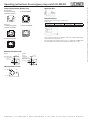
Operating instructions for emergency stop switch ES-XW/XN Removing/Installing Contact Block and Panel Mounting Removing First unlock the operator button. Squeeze the latch lever on the yellow bayonet ring and pull back the bayonet ring with force until the latch pin clicks, then turn the contact block counter-clockwise and pull out. Notes for removing the contact block 1) With the button in the locked position, do not remove the contact block, otherwise the switch may be damaged. 2) When the contact block is removed, the monitor contact (NO contact) is closed. 3) While removing the contact block, do not exert an excessive force, otherwise the switch may be damaged. 4) An LED lamp is built into the contact block for illuminated pushbuttons. When removing the contact block, pull out the contact block straight to prevent damage to the LED lamp. If an excessive force is exerted, the LED lamp may be damaged and fail to light. Panel Mounting Remove the locking ring from the operator and check that the rubber gasket is in place. Align the anti-rotation projection on the bezel with the recess in the panel, insert the operator from panel front into the panel hole and tighten the locking ring using ring wrench ES-XN9Z-T1 to a torque of 2.5Nm. Face the side without thread on the operator with TOPmarking upward, and tighten the locking ring using ring wrench ES-MW9Z-T1 to a torque of 2.0Nm. Rubber gasket Rubber gasket Recess TOP marking TOP marking Sleeve without threed Locking ring ES-XW... Anti-rotation projection Locking ring ES-XN About anti-rotation To prevent the ES-XW emergency stop switch from rotating when resetting from the latched position with excessive force, use of a nameplate (ES-HWAV-27) is recommended. Align the side without thread on the operator with TOP marking, the small ▲ marking on the projection on the nameplate, and the recess on the mounting panel. 250V Conventional Free Air Thermal Current (Ith) 5A ▼ making ▲ making (Turn clockwise) TOP making Notes for Operation When using the emergency stop switch for safetyrelated equipment in a control system, refer to the safety satandards and regulations in each country and region depending on the application purpose of the actual machines and installations to make sure of correct operation. Before using the emergency stop switch, perform risk assessment to make sure of safety. Wiring Tighten the terminal screws to a torque of 0.6 to 0.8 Nm. Contact Bouncing When the button is reset by pulling or turning, the NC main contacts cause bouncing. When pressing the button, the NO monitor contacts cause bouncing. When designing a control circuit, take the bouncing into consideration (reference value: 20 ms). LED Illuminated Switches The LED lamp is built into the contact block and cannot be replaced. Handling Do not expose the switch to excessive shocks and vibrations, otherwise the switch may be deformed or damaged, causing malfunction or operation failure. Padlock Emergency Stop (ES-XN) The padlockable emergency stop switches can be reset by turning only, and cannot be pulled to reset. Do not attempt to pull to reset, otherwise damage or malfunction may result. Main Contact Projection Before installing the emergency stop nameplate, break the projection on the nameplate using pliers. Installing First unlock the operator button. Align the small ▼ marking on the edge of the operator sleeve with the small ▲ marking on the yellow bayonet ring. Hold the contact block, not the bayonet ring. Press the contact block onto the operator and turn the contact block clockwise until the bayonet ring clicks. Notes for installing the contact block 1) With the button in the locked position, do not install the contact block, otherwise the switch may be damaged. 2) Make sure that the bayonet ring is secured in the locked position. (Push) (Squeeze) Latch lever Rated Insulation Voltage (Ui) Rated Operational Voltage (Ue) Bayonet ring (Turn counterclockwise) (Squeeze) (Pull) Contact Ratings [Main Contact (NC) and Monitor Contact (NO)] Monitor Contact Read this instruction sheet and the catalog for the ES-XN/XW series emergency stop switches to make sure of correct operation before starting installation, wiring, operation, maintenance, and inspection. Make sure that the instruction sheet is kept by the end user. Turn off the power to the ES-XN/XW before starting installation, wiring, maintenance and inspection of the ES-XN/XW. Failure to turn power off may cause electric shock or fire hazard. Use wires of a proper size to meet voltage and current requirements. Tighten the M3 terminal screws to a tightening torque of 0.6 to 0.8 Nm. Improper wires and loose terminals during operation will cause overheating and fire hazard. Provide a proper protection against electric shocks. When using the ES-XN emergency stop nameplate (ES-HNAV-27). Rated Operational Current SAFETY NOTE AC Resistive Load (AC-12) 50/60Hz Inductive Load (AC-15) DC 125V - 5A 250V 3A - 3A 1.5A Resistive Load (DC-12) 2A 0.4A 0.2A Inductive Load (DC-13) 1A 0.22A 0.1A - 1.2A 0.6A - 0.6A 0.3A Resistive Load (DC-12) 2A 0.4A 0.2A Inductive Load (DC-13) 1A 0.22A 0.1A AC Resistive Load (AC-12) 50/60Hz Inductive Load (AC-14) DC 30V Built-in LED Ratings Rated Voltage Operating Voltage Operating Current 24V AC/DC 24V AC/DC±10% 15 mA Specifications Applicable Standard IEC 60947-5-1, EN 60947-5-1 IEC 60947-5-5, EN 60947-5-5 JIS C8201-5-1, JIS C8201-5-5, UL508, UL991, NFPA79, CSA C22.2 No.14, GB14048-5 Standard Operating Operating temperature Conditions Non illuminated : -25 to +60 °C (no freezing) LED illuminated : -25 to +55 °C (no freezing) Relative humidity : 45 to 85 % RH (no condensation) Storage temperature : -45 to +80 °C (no freezing) Minimum Direct 80 N Opening Force Minimum Direct 4.0 mm Opening Travel Maximum Travel 4.5 mm Contact Resistance 50 mΩ maximum (initial value) Insulation Resis100 MΩ minimum (500V DC megger) tance Over voltage II Category Impulse Withstand 2.5 kV Voltage Pollution Degree 3 Operating Fre900 operations/hour quency Mechanical Life 250,000 operations min Electrical Life 100,000 operations min 250,000 operations min (24V AC/DC, 100mA) Shock Resistance Operating extremes : 150 m/s² Damage limits : 1,000 m/s² Vibration Resistance Operating extremes :10 to 500 Hz, amplitude 0.35mm, acceleration 50 m/s² Damage limits:10 to 500 Hz, amplitude 0.35mm, acceleration 50 m/s² Degree of ProIP65 (panel front) tection Terminal Protection Short-circuit Protective Device Conditional Shortcircuit Current Applicable Tightening Torque Applicable Wire ES-XW Recommended Tightening Torque of Locking Ring ES-XN Recommended Tightening Torque of Locking Ring Total Weight of Padlock and Hasp Reinforced Insulation (IEC 60664-1) IP20 250V/10A fuse (Type aM IEC60269-1/ IEC60269-2) 1,000 A 0.6 to 0.8 Nm 0.75 to 1.25 mm² (AWG18 to 16) 2.0 Nm 2.5 Nm 1500g maximum Between live parts and Bezel Contact Arrangements (Bottom View) Non-illuminated ES-XW1E-BV412MFR/ ES-XN4E-BL412MFRH ES-XW1E-BV404MFR 12 31 11 32 11 L 24 R L 41 21 42 32 31 32 12 11 R Padlock and Hasp Applicable padlock and hasp are shown below. Padlock size 31 a b c d 7 mm maximum 19 mm minimum 39 mm minimum 15 mm minimum*) *) Dimension d is 6 mm or more when attaching a padlock from the side of a switch. ES-XW1E-LV404Q4MFR 11 X1 24 12 22 23 Illuminated ES-XW1E-LV412Q4MFR/ ES-XN4E-LL412Q4MFR L Applicable Wire 12 41 22 R L 21 23 X2 LED 24V X1 32 R 42 31 X2 Since various from and sizes are available, make sure of applicability using the actual padlock and hasp before use. The total weight of the padlock and hasp can be a maximum of 1500g. When the total weight exceeds this limit, the switch may malfunction or fail. ES-XW1E-LV413Q4MFR 11 12 41 22 L 21 LED 24V X1 34 R 42 33 X2 Mounting Hole Dimensions ES-XN R0.8 maximum Φ30.5 +0.5 0 4.8 +0.2 0 +0.5 0 +0.4 0 24.1 φ 22.3 3.2 +0.4 0 R0.8 maximum +0.2 0 33.0 ES-XW LED Unit Internal Circuit X1 R LED X2 EUCHNER GmbH + Co. KG Kohlhammerstraße 16 D-70771 Leinfelden-Echterdingen Tel. +49 711 7597-0 Fax +49 711 7533-16 www.euchner.de [email protected] Subject to technical modifications; no responsibility is accepted for the accuracy of this information. © EUCHNER GmbH + Co. KG 105026-07-06/12 Operating instructions for emergency stop switch ES-XW/XN