1
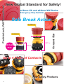
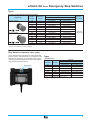
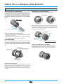
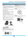
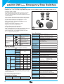
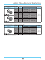
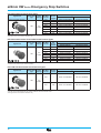
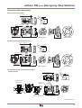
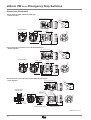
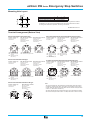
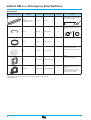
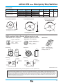
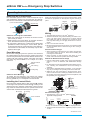
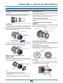
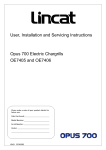
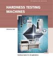
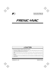
ø16mm XA Series
ø22mm XW Series
Emergency Stop Switches
ø16mm XA and ø22mm XW Series
Emergency Stop Switches
Safe Break Action
ø22 XW Series
ø16 XA Series
48.7 mm
Actual
Size
27.9 mm
Compact Size
Push-to-Lock, Pull/Turn-to-Reset
New Global Standard for Safety!
Up to 4 Poles of Contacts
New Safety Products
2
Safety
World’s
First
Safe Break Action
When the contact block is detached from the operator, the cam
directly opens the NC main contacts (contacts are off).
Compact Size
ø16 XA Series
World’s
First
The depth behind the panel is 27.9 mm.
Up to 4 contacts are available!
Detaching the Contact Block
Operator
Same dimensions
for any number of
contacts!
Contact Block
Closed
(ON)
Open
(OFF)
27.9
mm
Safety Features
Conventional Emergency Stop Switches
Normal Status
Latched
XA/XW Series Emergency Stop Switches
Normal Status
Latched
World's
ø22 XW Series
NC contacts:
OFF (machine
cannot
operate)
NC contacts:
OFF (machine
cannot
operate)
NC contacts:
ON (machine
can operate)
The depth behind the panel:
Solder terminal: 37.1 mm
Screw terminal: 48.7 mm
Up to 4 contacts save space.
Same dimensions
for any number of
contacts!
Energy
Normal
NC contacts are always on
standby to turn on
(hazardous)
Operator Stroke
Latched
Low
Low
Energy
High
High
NC contacts:
ON (machine
can operate)
Shortest
Normal
Conventional
Emergency Stop Switch
NC contacts are always on
standby to turn off (safe)
Operator Stroke
Latched
With the XA and XW emergency stop switches, the energy level of the “on”
(closed) NC contacts is higher than that of the “off” (open) contacts. If the
contact block falls off due to excessive shocks, the NC contacts are always
inclined to turn off, thus ensuring safety by stopping the machine.
48.7
mm
Direct Opening Action
IEC60947-5-5, 5.2, IEC60947-5-1, Annex K
Space Saving!
Safety Lock Mechanism
IEC60947-5-5, 6.2
As of June, 2004
Easy Operation
Variety
Three terminal styles
Push-to-lock, Pull/Turn-to-unlatch
The XA and XW emergency stop switches can be unlatched by
either pulling or turning the operator.
Unlatching by pulling
Unlatching by turning
Screw Terminal
Solder Terminal
PC Board Terminal
Two button colors
Bright Red
Munsell 7.5R4.5/14
Dark Red
Munsell 5R4/12
3
ø16mm XA Series Emergency Stop Switches
The World’s First ø16 mm, 4-contact Emergency Stop Switch.
Compact size - only 27.9 mm deep behind the panel.
• Lead-free, RoHS compliant.
• The depth behind the panel is only 27.9 mm for 1 to 4 contacts.
• IDEC’s original “Safe break action” ensures that the contacts open when the contact block is detached from the
operator.
• 1 to 4NC main contacts and 1NO monitor contact
• Push-to-lock, Pull or Turn-to-reset operator
• Direct opening action mechanism (IEC60947-5-5, 5.2,
IEC60947-5-1, Annex K)
• Safety lock mechanism (IEC60947-5-5, 6.2)
• Degree of protection IP65 (IEC60529)
• Two operator sizes: ø29 and ø40 mm
• Dark red (Munsell 5R4/12) or bright red (Munsell 7.5R4.5/
14) colors are available for the operator of emergency stop
switches, and gray for stop switch operators.
• UL, c-UL approved. EN compliant
Direct Opening Action
Specifications
Standard
UL508
CSA C22.2 No. 14
EN60947-5-1
EN60947-5-5 (Note)
Approval Organization/
File No.
Mark
Operating Humidity
45 to 85% RH (no condensation)
Storage Temperature
–45 to +80°C
TÜV Product Service
Operating Force
Push to lock: 10.5N
Pull to reset: 10N
Turn to reset: 0.16 N·m
Self-declaration (European
Commission’s Low Voltage
Directive)
Minimum Force
Required for Direct
Opening Action
60N
Minimum Operator
Stroke Required for
Direct Opening Action
4.0 mm
Maximum Operator
Stroke
4.5 mm
Contact Ratings
(NC main contacts/NO monitor contact)
Rated Insulation Voltage (Ui)
Rated Current (Ith)
Rated Operating Voltage (Ue)
Resistive Load
(AC-12)
Inductive Load
(AC-15)
Resistive Load
(DC-12)
DC
Inductive Load
(DC-13)
Resistive Load
(AC-12)
AC 50/60 Hz
Inductive Load
(AC-14)
Resistive Load
(DC-12)
DC
Inductive Load
(DC-13)
30V
–
300V
5A
125V
3A
250V
3A
Rated Operating Current
AC 50/60 Hz
Monitor
Contacts
IEC60947-5-1, EN60947-5-1
IEC60947-5-5 (Note), EN60947-5-5 (Note)
JIS C8201-5-1, UL508, CSA C22.2 No. 14
Operating Temperature –25 to +60°C (no freezing)
UL/c-UL File No. E68961
Note: Except for stop switches (operator color: gray).
Main
Contacts
Applicable Standards
–
1.5A
1.5A
2A
0.4A
0.2A
1A
0.22A
0.1A
–
1.2A
0.6A
–
0.6A
0.3A
2A
0.4A
0.2A
1A
0.22A
0.1A
• Minimum applicable load: 5V AC/DC, 1 mA (reference value)
(Operating area may vary according to the operating conditions and load
types.)
• The rated operating currents are measured at resistive/inductive load types
specified in JIS C8201-5-1.
Contact Resistance
50 mΩ maximum (initial value)
Insulation Resistance
100 MΩ minimum (500V DC megger)
Overvoltage Category
II
Impulse Withstand
Voltage
2.5 kV
Pollution Degree
3
Operation Frequency
900 operations/hour
Shock Resistance
Operating extremes: 150 m/s2
Damage limits:
1000 m/s2
Vibration Resistance
Operating extremes: 10 to 500 Hz, amplitude 0.35 mm
acceleration 50 m/s2
Damage limits:
10 to 500 Hz, amplitude 0.35 mm
acceleration 50 m/s2
Mechanical Life
250,000 operations minimum
Electrical Life
100,000 operations minimum
250,000 operations minimum (24V AC/DC, 100 mA)
Degree of Protection
IP65 (IEC60529)
Short-circuit Protection 250V/10A fuse (Type aM, IEC60269-1/IEC60269-2)
Conditional
Short-circuit Current
1000A
Terminal Style
Solder terminal, PC Board terminal
Recommended
Tightening Torque
for Locking Ring
0.88 N·m
Connectable Cable
1.25 mm2 maximum (AWG16 maximum)
Soldering Conditions
20W/5 seconds maximum, or 260°C/3 seconds
maximum
Weight
ø29 mm type: 23 g, ø40 mm type: 28 g
Note: Except for stop switches (operator color: gray).
4
ø16mm XA Series Emergency Stop Switches
Types
Solder Terminal/PC Board Terminal Types
Appearance
ø29mm Operator
ø40mm Operator
NC Main
Contact
NO Monitor
Contact
1NC
2NC
3NC
4NC
1NC
2NC
3NC
1NC
2NC
3NC
4NC
1NC
2NC
3NC
—
—
—
—
1NO
1NO
1NO
—
—
—
—
1NO
1NO
1NO
Type No.
Terminal Style
Solder Terminal
PC Board Terminal
XA1E-BV301∗
XA1E-BV301V∗
XA1E-BV302∗
XA1E-BV302V∗
XA1E-BV303∗
XA1E-BV303V∗
XA1E-BV304∗
XA1E-BV304V∗
XA1E-BV311∗
XA1E-BV311V∗
XA1E-BV312∗
XA1E-BV312V∗
XA1E-BV313∗
XA1E-BV313V∗
XA1E-BV401∗
XA1E-BV401V∗
XA1E-BV402∗
XA1E-BV402V∗
XA1E-BV403∗
XA1E-BV403V∗
XA1E-BV404∗
XA1E-BV404V∗
XA1E-BV411∗
XA1E-BV411V∗
XA1E-BV412∗
XA1E-BV412V∗
XA1E-BV413∗
XA1E-BV413V∗
Operator
Color Code
R: Dark red
RH: Bright red
• Specify a color code in place of ∗ in the Type No.
• Terminal cover (XA9Z-VL2) is ordered separately.
Stop Switches (operator color: gray)
Some mobile teaching pendants are easily detachable
from the system, and stop switches, not emergency stop
switches, are required on such pendants. IDEC’s graycolored stop switches avoid the confusion of emergency
stop switches and stop switches.
Stop Switch
Types
• Stop Switches
NC Main
Contacts
NO Monitor
Contacts
1NC
2NC
3NC
4NC
1NC
2NC
3NC
—
—
—
—
1NO
1NO
1NO
Type No.
Terminal Style
Solder Terminal
PC Board Terminal
XA1E-BV301N
XA1E-BV301VN
XA1E-BV302N
XA1E-BV302VN
XA1E-BV303N
XA1E-BV303VN
XA1E-BV304N
XA1E-BV304VN
XA1E-BV311N
XA1E-BV311VN
XA1E-BV312N
XA1E-BV312VN
XA1E-BV313N
XA1E-BV313VN
• Operator is ø29 mm and gray-colored (code: N).
5
AS-Interface Components
ø16mm XA Series Emergency Stop Switches
Dimensions
• ø29mm Operator
Panel Thickness 0.5 to 3.7
1.7
+0
.2
0
17.9
27.2
19.8
8.7
6.2
+0.2
0
+0.2
0
ø1
PC Board Layout
(Bottom View)
Panel Cut-out
Gasket
Terminal Cover
XA9Z-VL2
19.8
8.7
ø2
9
.2
Locking Ring
.8
les
ho
9
ø2
11.2
19.8
8.7
30.4
ø1
8-
3-ø
1.7
ho
2.1
les
6.5
25.8
3.1
29.4
20.6
30.4
PC Board Terminal Type
• ø40mm Operator
Solder Terminal Type
Panel Thickness 0.5 to 3.7
1.7
+0
.2
0
17.9
27.2
19.8
8.7
6.2
+0.2
0
ø1
+0.2
0
PC Board Layout
(Bottom View)
Panel Cut-out
Terminal Cover
XA9Z-VL2
ø2
les
2
.
ø1
Gasket
Locking Ring
9.
8
19.8
8.7
ho
0
ø4
30.4
11.2
8.7
19.8
8-
3-ø
1.7
6.5
ho
les
25.8
2.1
29.4
30.4
3.1
PC Board Terminal Type
20.6
Solder Terminal Type
All dimensions in mm.
• NC main contacts only
• The values shown above are the
minimum dimensions for mounting
with other ø16 mm pushbuttons. For
other control units of different sizes
and styles, determine the values
according to the dimensions, operation, and wiring convenience.
TOP
1
TOP
2
1
Left
Right
2
1
1NC: Terminals on right
2NC: Terminals on right and left
3NC: Terminals on right, left, and top
6
2
1
50 mm minimum
2
40 mm minimum
XA1E-BV4
Left
Right
2
X
XA1E-BV3
NC main contacts: Terminals 1-2
NO monitor contacts: Terminals 3-4
1
Y
Y
2
X
• With NO monitor contacts
NC main contacts: Terminals 1-2
2
+0.2
0
1
ø16.2
Terminal Arrangement (Bottom View)
1
Mounting Hole Layout
4
3
1NC: Terminals on top
2NC: Terminals on right and left
ø16mm XA Series Emergency Stop Switches
Accessories
Description & Appearance
Material
Ordering
Type No.
Type No.
Package
Quantity
Remarks
Ring Wrench
Metal
(nickel-plated brass)
MT-001
MT-001
• Used to tighten the locking ring
when installing the XA emergency
stop switch onto a panel.
• The recommended tightening
torque is 0.88 N·m at maximum.
1
Locking Ring
• Black
Plastic
HA9Z-LN
HA9Z-LNPN10
10
Terminal Cover
• White
• Used for solder terminals.
• Also applicable to the XW series.
PBT
XA9Z-VL2
XA9Z-VL2PN02
2
Nameplates
Description
Legend
(blank)
For ø29mm Operator
For ø40mm Operator
Type No.
EMERGENCY STOP
HAAV-27
(blank)
HAAV4-0
EMERGENCY STOP
HAAV4-27
• For ø29mm Operator
Material
Plate Color
Legend Color
Polyamide
Yellow
Black
HAAV-0
• For ø40mm Operator
3.5
ø4
0
ø6
ø1
6
1.7
0.3
• Panel thickness when using the nameplate: 0.5 to 2 mm
ø1
6
1.7
0.5
• Panel thickness when using the nameplate: 0.5 to 2 mm
All dimensions in mm.
7
AS-Interface Components
ø16mm XA Series Emergency Stop Switches
Operating Instructions
Removing the Contact Block
Installing the Contact Block
First unlock the operator button. While pushing up the white
bayonet ring, using a small screwdriver (width: 2.5 to 3 mm)
if necessary, turn the contact block counterclockwise and
pull out. Do not exert excessive force when using a
screwdriver, otherwise the bayonet ring may be damaged.
First turn the bayonet ring to the unlocked position.
Bayonet Ring
Bayonet Ring
Unlocked
Locked
Align the small ▲ marking on the edge of the operator base
with the TOP marking on the contact block. Press the contact block onto the operator and turn the contact block clockwise until the bayonet ring clicks.
➁ Turn counterclockwise
➀ Push
TOP marking
• Notes for Removing the Contact Block
1. When the contact block is removed, the monitor contact
(NO contact) is closed.
2. While removing the contact block, do not exert excessive
force, otherwise the switch may be damaged.
Panel Mounting
marking
➀ Press
Remove the locking ring from the operator and check that
the rubber gasket is in place. Insert the operator from panel
front into the panel hole. Face the side with the anti-rotation
protrusion on the operator upward, and tighten the locking
ring.
Operator Unit
Anti-rotation Protrusion
Rubber Gasket
Locking Ring
• Notes for Panel Mounting
To mount the XA emergency stop switches onto a panel,
tighten the locking ring to a tightening torque of 0.88 N·m
maximum using ring wrench MT-001. Do not use pliers. Do
not exert excessive force, otherwise the locking ring may be
damaged.
8
➁ Turn
TOP marking (contact block)
• Notes for Installing the Contact Block
Check that the contact block is securely installed on the
operator. When the emergency stop switch is properly
assembled, the bayonet ring is in place as shown below.
ø16mm XA Series Emergency Stop Switches
Operating Instructions
Wiring
Contact Bounce
1. The applicable wire size is 1.25 mm2 maximum.
When the button is reset by pulling or turning, the NC main
contacts will bounce. When pressing the button, the NO
monitor contacts will bounce.
2. Solder the terminals using a 20W soldering iron within 5
seconds, or at 260°C within 3 seconds. Do not apply
external force. Make sure that the soldering iron touches
the terminals only. When wiring, do not apply tensile force
on the terminals.
3. Use a non-corrosive rosin flux.
4. Because the terminal spacing is narrow, use protective
tubes or heat shrinkable tubes to avoid burning of wire
coating or short circuit.
When designing a control circuit, take the contact bounce
time into consideration (reference value: 20 ms).
Nameplate
When anti-rotation is not required, remove the projection
from the nameplate using pliers.
Projection
• PC Board Terminal Type
1. When mounting a contact block on a PC board, provide
sufficient rotating space for the PC board when installing
and removing the contact block.
2. When mounting an XA emergency stop switch on a PC
board, make sure that the operator is securely installed.
• About PC Board and Circuit Design
1. Use PC boards made of glass epoxy copper-clad laminated sheets of 1.6 mm in thickness, with double-sided
through hole.
Handling
2. PC boards and circuits must withstand rated voltage and
current, including the instantaneous current and voltage
at switching.
Do not expose the switch to excessive shock and vibration,
otherwise the switch may be deformed or damaged, causing malfunction or operation failure.
Nameplate
3. The minimum applicable load is 5V AC/DC, 1 mA. This
value may vary according to the operating environment
and load.
4. Within the 2.8∗ mm areas shown in the figure below, terminals touch the PC board, resulting in possible short circuit on the printed circuit. When designing a PC board
pattern, take this possibility into consideration.
19.8
8.7
(0.5)
les
1.2
ho
ø
0-
1.6
(PC Board)
2.8∗
(0.5)
(0.5)
(0.5)
2.8∗
19.8
8.7
1
Solder Surface
Surface for installing
components
Solder Surface
Surface for installing
components
2.8∗
2.8∗
All dimensions in mm.
• Installing Insulation Terminal Cover
To install the terminal cover (XA9Z-VL2), align the TOP
marking on the terminal cover with TOP marking on the contact block, and press the terminal cover toward the contact
block.
Note: For wiring, insert the wires into the holes in the terminal cover before
soldering.
9
ø22mm XW Series Emergency Stop Switches
ø22 mm, 4-contact Emergency Stop Switch.
Compact size - only 37.1 mm deep behind the panel (screw terminal type 48.7 mm with terminal cover).
• Lead-free, RoHS compliant.
• The depth behind the panel is only 37.1 mm for 1 to 4 contacts (screw terminal type 48.7 mm with terminal cover).
• The same depth behind the panel for illuminated and non-illuminated switches.
• IDEC’s original “Safe break action” ensures that the contacts
open when the contact block is detached from the operator.
• 1 to 4NC main contacts and 1 or 2NO monitor contact
• Push-to-lock, Pull or Turn-to-reset operator
• Direct opening action mechanism (IEC60947-5-5, 5.2,
IEC60947-5-1, Annex K)
• Safety lock mechanism (IEC60947-5-5, 6.2)
• Degree of protection IP65 (IEC60529)
• Screw terminal type is finger-safe (IP20).
• Two operator sizes: ø40 and ø60 mm
• Dark red (Munsell 5R4/12) or bright red (Munsell 7.5R4.5/14)
Direct Opening Action
colors are available for the non-illuminated operator.
• Push-ON illumination type available (operator size: ø60)
• UL, c-UL approved. EN compliant
Specifications
Standard
Mark
UL508
CSA C22.2 No. 14
Approval Organization/
File No.
UL/c-UL File No. E68961
(solder terminal, PC board
terminal types)
UL/c-UL Listing
(screw terminal type only)
TÜV Product Service
EN60947-5-1
EN60947-5-5
Self-declaration (European
Commission’s Low Voltage
Directive)
Contact Ratings
(NC main contacts/NO monitor contact)
Rated Operating Current
Screw
Terminal Type
Solder
Rated Insulation Voltage (Ui) Terminal Type
PC Board
Terminal Type
Rated Current (Ith)
Rated Operating Voltage (Ue)
Resistive Load
(AC-12)
AC 50/60 Hz
Inductive Load
(AC-15)
Main
Contacts
Resistive Load
(DC-12)
DC
Inductive Load
(DC-13)
Resistive Load
(AC-12)
AC 50/60 Hz
Inductive Load
(AC-14)
Monitor
Contacts
Resistive Load
(DC-12)
DC
Inductive Load
(DC-13)
250V
300V
–
5A
125V
5A
(Note 1)
3A
(Note 2)
2A
0.4A
0.2A
1A
0.22A
0.1A
–
1.2A
0.6A
–
0.6A
0.3A
2A
0.4A
0.2A
1A
0.22A
0.1A
30V
–
250V
3A
1.5A
• Minimum applicable load: 5V AC/DC, 1 mA (reference value)
IEC60947-5-1, EN60947-5-1
IEC60947-5-5 (Note), EN60947-5-5 (Note)
JIS C8201-5-1, UL508, CSA C22.2 No. 14
Non-illuminated: –25 to +60°C (no freezing)
Operating Temperature
LED illuminated: –25 to +55°C (no freezing)
Operating Humidity
45 to 85% RH (no condensation)
Storage Temperature
–45 to +80°C
Push to lock: 32N
Operating Force
Pull to reset: 21N
Turn to reset: 0.27 N·m
Minimum Force
Required for Direct
80N
Opening Action
Minimum Operator
Stroke Required for
4.0 mm
Direct Opening Action
Maximum Operator
4.5 mm
Stroke
Applicable Standards
Contact Resistance
Insulation Resistance
Overvoltage Category
Impulse Withstand
Voltage
Pollution Degree
Operation Frequency
50 mΩ maximum (initial value)
100 MΩ minimum (500V DC megger)
II
Terminal Style
Recommended
Tightening Torque for
Locking Ring
Solder terminal, PC board terminal, M3 screw terminal
2.5 kV
3
900 operations/hour
Operating extremes: 150 m/s2
Shock Resistance
Damage limits:
1000 m/s2
Operating extremes: 10 to 500 Hz, amplitude 0.35 mm,
acceleration 50 m/s2
Vibration Resistance
Damage limits:
10 to 500 Hz, amplitude 0.35 mm,
acceleration 50 m/s2
Mechanical Life
250,000 operations minimum
100,000 operations minimum
Electrical Life
250,000 operations minimum (24V AC/DC, 100 mA)
Degree of Protection
IP65 (IEC60529)
Short-circuit Protection 250V/10A fuse (Type aM, IEC60269-1/IEC60269-2)
Conditional
1000A
Short-circuit Current
(Operating area may vary according to the operating conditions and load types.)
2.0 N·m
Screw terminal type: 0.75 to 1.25 mm2 (AWG18 to 16)
Solder terminal / PC board terminal types:
1.25 mm2 maximum (AWG16 maximum)
20W/5 seconds maximum, or 260°C/3 seconds
maximum
• The rated operating currents are measured at resistive/inductive load types
specified in JIS C8201-5-1.
Connectable Cable
Note 1: Solder terminal/PC board terminal types: 3A
Note 2: Solder terminal/PC board terminal types: 1.5A
Soldering Conditions
Illumination Ratings
Recommended
Tightening Torque for
Terminal Screw
0.6 to 1.0 N·m
Weight
ø40 mm type: 72 g
ø60 mm type: 81 g
Rated Voltage
24V AC/DC
10
Operating Voltage
24V AC/DC ±10%
Rated Current
15 mA
ø22mm XW Series Emergency Stop Switches
Non-illuminated Screw Terminal Types
Appearance
ø40mm Operator
ø60mm Operator
NC Main
Contact
NO Monitor
Contact
1NC
2NC
3NC
4NC
1NC
2NC
3NC
2NC
1NC
2NC
3NC
4NC
1NC
2NC
3NC
2NC
—
—
—
—
1NO
1NO
1NO
2NO
—
—
—
—
1NO
1NO
1NO
2NO
Type No.
IP20
w/Terminal Cover
XW1E-BV401MF∗
XW1E-BV401M∗
XW1E-BV402MF∗
XW1E-BV402M∗
XW1E-BV403MF∗
XW1E-BV403M∗
XW1E-BV404MF∗
XW1E-BV404M∗
XW1E-BV411MF∗
XW1E-BV411M∗
XW1E-BV412MF∗
XW1E-BV412M∗
XW1E-BV413MF∗
XW1E-BV413M∗
XW1E-BV422MF∗
XW1E-BV422M∗
XW1E-BV501MF∗
XW1E-BV501M∗
XW1E-BV502MF∗
XW1E-BV502M∗
XW1E-BV503MF∗
XW1E-BV503M∗
XW1E-BV504MF∗
XW1E-BV504M∗
XW1E-BV511MF∗
XW1E-BV511M∗
XW1E-BV512MF∗
XW1E-BV512M∗
XW1E-BV513MF∗
XW1E-BV513M∗
XW1E-BV522MF∗
XW1E-BV522M∗
Operator
Color Code
R: Dark red
RH: Bright red
• Specify a color code in place of ∗ in the Type No.
• IP20 types can be connected to solid wires only.
Non-illuminated Solder Terminal/PC Board Terminal Types
Appearance
ø40mm Operator
NC Main
Contact
NO Monitor
Contact
1NC
2NC
3NC
4NC
1NC
2NC
3NC
2NC
—
—
—
—
1NO
1NO
1NO
2NO
Type No.
Terminal Style
Solder Terminal
PC Board Terminal
XW1E-BV401∗
XW1E-BV401V∗
XW1E-BV402∗
XW1E-BV402V∗
XW1E-BV403∗
XW1E-BV403V∗
XW1E-BV404∗
XW1E-BV404V∗
XW1E-BV411∗
XW1E-BV411V∗
XW1E-BV412∗
XW1E-BV412V∗
XW1E-BV413∗
XW1E-BV413V∗
XW1E-BV422∗
—
Operator
Color Code
R: Dark red
RH: Bright red
• Specify a color code in place of ∗ in the Type No.
• Terminal cover (XA9Z-VL2) is ordered separately.
11
AS-Interface Components
ø22mm XW Series Emergency Stop Switches
LED Illuminated Screw Terminal Types
Appearance
Illumination
Type
Rated
Voltage
NC Main
Contact
24V
AC/DC
1NC
2NC
3NC
4NC
1NC
2NC
3NC
2NC
ø40mm Illuminated Operator
LED
NO
Monitor
Contact
—
—
—
—
1NO
1NO
1NO
2NO
Type No.
IP20
w/Terminal Cover
XW1E-LV401Q4MFR
XW1E-LV402Q4MFR
XW1E-LV403Q4MFR
XW1E-LV404Q4MFR
XW1E-LV411Q4MFR
XW1E-LV412Q4MFR
XW1E-LV413Q4MFR
XW1E-LV422Q4MFR
XW1E-LV401Q4MR
XW1E-LV402Q4MR
XW1E-LV403Q4MR
XW1E-LV404Q4MR
XW1E-LV411Q4MR
XW1E-LV412Q4MR
XW1E-LV413Q4MR
XW1E-LV422Q4MR
• The operator color is red only.
• IP20 types can be connected to solid wires only.
LED Illuminated Solder Terminal/PC Board Terminal Types
Appearance
Illumination
Type
Rated
Voltage
NC Main
Contact
NO
Monitor
Contact
24V
AC/DC
1NC
2NC
3NC
4NC
1NC
2NC
3NC
2NC
—
—
—
—
1NO
1NO
1NO
2NO
ø40mm Illuminated Operator
LED
Type No.
Terminal Style
Solder Terminal
PC Board Terminal
XW1E-LV401Q4R
XW1E-LV401Q4VR
XW1E-LV402Q4R
XW1E-LV402Q4VR
XW1E-LV403Q4R
XW1E-LV403Q4VR
XW1E-LV404Q4R
XW1E-LV404Q4VR
XW1E-LV411Q4R
XW1E-LV411Q4VR
XW1E-LV412Q4R
XW1E-LV412Q4VR
XW1E-LV413Q4R
XW1E-LV413Q4VR
XW1E-LV422Q4R
—
• The operator color is red only.
• Terminal cover (XA9Z-VL2) is ordered separately.
Push-ON LED Illuminated Screw Terminal Types
Appearance
Illumination
Type
Rated
Voltage
NC Main
Contact
NO
Monitor
Contact
IP20
w/Terminal Cover
3NC
—
XW1E-TV403Q4MFR
XW1E-TV403Q4MR
2NC
1NO
XW1E-TV412Q4MFR
XW1E-TV412Q4MR
Type No.
ø40mm Illuminated Operator
LED
24V
AC/DC
• The operator color is red only.
• Push-ON types is illuminated when the operator is latched, and turns off when reset.
• IP20 types can be connected to solid wires only.
12
ø22mm XW Series Emergency Stop Switches
Dimensions (Non-Illuminated)
• Screw Terminal Type (IP20)
Panel Thickness 0.8 to 6
R0
.8
ø2
+0.2
0
x.
+0
0 .4
R
24.1 0
+0.4
2.3
3.2
ma
Panel Cut-out
Gasket
Locking Ring
0.5
ø4
0
20.1
37
18.5
ø6
0
M3 Terminal Screw
48.7
IP20 Protection Cover
XW9Z-VL2MF
32
32
ø40mm Operator
ø60mm Operator
• Screw Terminal Type (w/terminal cover)
Panel Thickness 0.8 to 6
R0
.8
ø2
ma
x.
3.2
+0.2
0
+0
.
0 4
24.1
R
+0.4
0
2.3
Panel Cut-out
0
ø6
0.5
ø4
Gasket
Locking Ring
20.1
37
18.5
0
M3 Terminal Screw
47.2
48.7
32
32
ø40mm Operator
• Solder Terminal and PC Board Terminal Types
ø40mm Operator
ø60mm Operator
R0
Panel Thickness 0.8 to 6
.8
ma
x.
ø2
+0
.
0 4
3.2
+0.2
0
24.1
R
19.8
8.7
2.3
+0.4
0
Terminal Cover
XW9Z-VL2M
Panel Cut-out
PC Board Layout
(Bottom View)
17.4
19.8
8.7
Terminal Cover
XA9Z-VL2
20.1
Gasket
Locking Ring
les
.2
ho
0
ø4
33.6
19.8
8.7
11.2
33.6
19.8
8.7
ø1
8-
3-ø
6.5
1.7
ho
les
3.1
2.1
35
39.6
PC Board Terminal Type
0.5
32
Solder Terminal Type
All dimensions in mm.
13
AS-Interface Components
ø22mm XW Series Emergency Stop Switches
Dimensions (Illuminated)
• Screw Terminal (IP20) LED Illuminated Type
ø40mm Operator
Panel Thickness 0.8 to 6
R0
.8
ma
3.2
x.
ø2
2.3
+0.2
0
R
24.1 0
+0.4
+0
0 .4
Panel Cut-out
LED Push-ON Type
M3 Terminal Screw
0.5
Gasket
Locking Ring
37
20.1
ø4
0
18.5
20.1
18.5
IP20 Protection Cover
XW9Z-VL2MF
48.7
32
• Screw Terminal (w/terminal cover) LED Illuminated Type
ø40mm Operator
Panel Thickness 0.8 to 6
R0
.8
ø2
ma
3.2
x.
+0.2
0
+0
.
0 4
R
+0.4
24.1 0
2.3
Panel Cut-out
LED Push-ON Type
M3 Terminal Screw
Gasket
Locking Ring
20.1
0.5
0
18.5
ø4
20.1
37
18.5
47.2
48.7
32
• Solder Terminal and PC Board Terminal LED Illuminated Types
40mm Operator
Panel Thickness 0.8 to 6
R0
.8
8.7
5.7
2.3
+0
.
0 4
3.2
+0.2
0
24.1
R
19.8
ma
x.
ø2
+0.4
0
Terminal Cover
XW9Z-VL2M
Panel Cut-out
PC Board Layout
(Bottom View)
19.8
8.7
5.7
les
.2
17.4
Terminal Cover
XA9Z-VL2
20.1
Gasket
Locking Ring
ho
0
ø4
1
-ø
33.6
19.8
8.7
11.2
19.8
8.7
10
3-ø
1.7
6.5
ho
les
3.1
2.1
35
39.6
PC Board Terminal Type
0.5
32
Solder Terminal Type
All dimensions in mm.
14
ø22mm XW Series Emergency Stop Switches
Mounting Hole Layout
ø22.3
+0.4
0
X
Y
Y
Screw Terminal Type
70 mm minimum
Solder/PC Board Terminal Type
50 mm minimum
• The values shown above are the minimum dimensions for mounting with other ø22mm
pushbuttons. For other control units of different sizes and styles, determine the values
according to the dimensions, operation, and wiring convenience.
X
All dimensions in mm.
Terminal Arrangement (Bottom View)
TOP
Right
TOP
2
Right
3
4
1
X1
4
3
X1 X2
LED
1
2
1
2
1
1NC: Terminals on right
2NC: Terminals on right
and left
3NC: Terminals on right,
left, and top
Left
X1
X2
4
3
1NC: Terminals on top
2NC: Terminals on right
and left
Left
X1
X2
4
3
1
2
Right
2
LED
Right
2
2
Right
2
X2
LED
1
1
1
X2
X1
TOP
4
Solder Terminal Type only
Notes:
• For screw terminal types, the back label of contact block shows the terminal
numbers of contacts in two digits. The number in ten digits show the contact
number, while the number in the units place show the contact codes (NC main
contact: 1-2, NO monitor contact: 3-4).
• For solder terminal and PC board terminal types, the contact block is marked
with contact codes (NC main contact 1-2: black, NO monitor contact 3-4: blue).
1
2
4
3
Left
3
Left
Right
2
2
Right
1
Left
1
LED
1
2
TOP
3
4
LED
1
X1
With 1NO monitor contacts
NC main contacts:
Terminals 1-2
NO monitor contacts:
Terminals 3-4
2
LED
Right
X2
1NC: Terminals on top
2NC: Terminals on right and left
TOP
1
3
With 2NO monitor contacts
NC main contacts:
Terminals 1-2
NO monitor contacts:
Terminals 3-4
TOP
2
2
1
Left
• Screw Terminal Illuminated Push-ON Type
NC main contacts only
NC main contacts:
Terminals 1-2
4
Solder Terminal Type only
With 1NO monitor contacts
NC main contacts:
Terminals 1-2
NO monitor contacts:
Terminals 3-4
TOP
4
2
Right
1
X2
2
LED
Left
1
2
1NC: Terminals on right
2NC: Terminals on right
and left
3NC: Terminals on right,
left, and top
Right
3
1NC: Terminals on top
2NC: Terminals on right
and left
2
3
2
X1
2
1
Right
4
NC main contacts only
NC main contacts:
Terminals 1-2
TOP
2
1
2
1
2
LED
Left
Left
1
With 2NO monitor contacts
NC main contacts:
Terminals 1-2
NO monitor contacts:
Terminals 3-4
2
1
1
1NC: Terminals on right
2NC: Terminals on right
and left
3NC: Terminals on right,
left, and top
TOP
2
4
• Solder Terminal/PC Board Terminal Illuminated Types
With 1NO monitor contacts
NC main contacts:
Terminals 1-2
NO monitor contacts:
Terminals 3-4
TOP
1
2
2
3
1NC: Terminals on top
2NC: Terminals on right and left
• Screw Terminal Illuminated Type
NC main contacts only
NC main contacts:
Terminals 1-2
3
Right
1
4
TOP
2
Left
1
1
1
Left
1
2
1NC: Terminals on right
2NC: Terminals on right
and left
3NC: Terminals on right,
left, and top
With 2NO monitor contacts
NC main contacts:
Terminals 1-2
NO monitor contacts:
Terminals 3-4
1
1
Left
1
Right
1
2
4
2
1
Left
2
1
3
1
Right
2
Left
TOP
2
2
1
2
1
With 1NO monitor contacts
NC main contacts:
Terminals 1-2
NO monitor contacts:
Terminals 3-4
1
TOP
2
NC main contacts only
NC main contacts:
Terminals 1-2
1
With 2NO monitor contacts
NC main contacts:
Terminals 1-2
NO monitor contacts:
Terminals 3-4
2
TOP
1
• Non-illuminated Solder Terminal/PC Board Terminal Types
With 1NO monitor contacts
NC main contacts:
Terminals 1-2
NO monitor contacts:
Terminals 3-4
2
NC main contacts only
NC main contacts:
Terminals 1-2
2
• Screw Terminal Non-illuminated Type
X1 X2
15
AS-Interface Components
ø22mm XW Series Emergency Stop Switches
Accessories
Description & Appearance
Material
Type No.
Ordering Type No.
Package
Quantity
Ring Wrench
Metal
(nickel-plated brass)
(weight: approx. 150 g)
• Used to tighten the locking ring
when installing the XW emergency
stop switch onto a panel.
MW9Z-T1
MW9Z-T1
1
Anti-rotation Ring
8
ø2
110
• The anti-rotation ring is used for
preventing the operator from turning.
Plastic
HW9Z-RL
HW9Z-RLPN10
1.5
10
Locking Ring
TOP
9
ø2
ø22
• Black
Plastic
HW9Z-LN
HW9Z-LNPN05
5
Terminal Cover
• White
• Used for solder terminals.
• Also applicable to the XA series.
PBT
XA9Z-VL2
XA9Z-VL2PN02
2
Terminal Cover
• Black
• Used for screw terminals.
PPE
XW9Z-VL2M
XW9Z-VL2MPN02
2
IP20 Protection Cover
Polyamide
XW9Z-VL2MF
XW9Z-VL2MFPN02
Note:
• XW emergency stop switches of screw terminal type are provided with a terminal cover.
• All dimensions in mm.
16
Remarks
2
• Black
• Used on terminals for IP20 finger
protection.
• Only solid wires can be used.
• The IP20 protection cover cannot
be removed once installed.
ø22mm XW Series Emergency Stop Switches
Nameplate
Description
Legend
For ø40mm Operator
For ø60mm Operator
HWAV-0
HWAV-0
EMERGENCY STOP
HWAV-27
HWAV-27
(blank)
HWAV5-0
HWAV5-0
EMERGENCY STOP
HWAV5-27
HWAV5-27
EMERGENCY STOP
HWAV5F-27
HWAV5F-27PN10
Material
Plate
Color
Legend
Color
Yellow
Black
Polyamide
1
PBT
10
• For ø60mm Operator
PET film sticker
• Sticker-type Nameplate
for ø60mm Operator
0
ø6
Y
E
ERGENC
Package
Quantity
Ordering Type No.
(blank)
• For ø40mm Operator
M
Type No.
ø80
ø80
ø2
2
STO P
1.5
0.9
0.6
7
2.3
2.
ø2
2
ø2
• Panel thickness when using
the nameplate: 0.8 to 4.5 mm
• Panel thickness when using
the marking plate: 0.8 to 4 mm
SEMI-compliant Switch Guards (ø22mm panel cut-out)
• SEMI S2-0200, 12.5.1 compliant
• SEMATECH Application Guide for
SEMI S2-93, 12.4 compliant
• Type No.: HW9Z-KG1
• Degree of Protection: IP65
• Color:
Yellow
• Package quantity: 1
• Type No.: HW9Z-KG2
• Degree of Protection: IP65
• Color:
Yellow
• Package quantity: 1
Dimensions
Dimensions
36.5
ø90
Gasket
2
ø2
Mounting
Mounting
TOP Marking
TOP Marking
Operator
Panel Thickness: 1.2 to 4
• Type No.: HW9Z-EMO-NPP
• Color:
Yellow (red legend)
• Package quantity: 10
˙
ø76.1
32
80
2
2.
ø2
38
22
64
48
• EMO Sticker
Locking Ring
TOP Marking
TOP Marking
Locking Ring
Operator
Panel Thickness: 1.2 to 4
All dimensions in mm.
• The HW9Z-KG1 and HW9Z-KG2 switch guards are applicable for ø40mm operators only.
Caution:
International industrial standards such as European Union Directive, IEC60204-1, and JIS B9960-1 require that emergency stop
switches must be installed in the manner in which the operator can access and operate the switches easily, and prohibit the use of
switch guards. The HW9Z-KG1 and HW9Z-KG2 switch guards are used for the emergency stop switches installed on semiconductor
manufacturing equipment only. Do not use the switch guards for emergency stop switches installed on machine systems such as
machine tool and food processing systems.
17
AS-Interface Components
ø22mm XW Series Emergency Stop Switches
Operating Instructions
Removing the Contact Block
Notes for installing the contact block
First unlock the operator button. Grab the bayonet ring ➀
and pull back the bayonet ring until the latch pin clicks ➁,
then turn the contact block counterclockwise and pull out ➂.
Make sure that the bayonet ring is in the locked position. Check
that the two projections on the bayonet ring are securely in
place.
➂ Turn counterclockwise
Latched
Unlatched
Bayonet Ring
Projections
➀ Grab
➀ Grab
➁ Pull
Wiring
• Notes for removing the contact block
1. When the contact block is removed, the monitor contact
(NO contact) is closed.
2. While removing the contact block, do not exert excessive
force, otherwise the switch may be damaged.
3. An LED lamp is built into the contact block for illuminated
pushbuttons. When removing the contact block, pull the
contact block straight to prevent damage to the LED lamp.
If excessive force is exerted, the LED lamp may be damaged and fail to light.
1. The applicable wire size is 1.25 mm2 maximum.
2. Solder the terminals using a 20W soldering iron within 5 seconds, or at 260°C within 3 seconds. Do not apply external
force. Make sure that the soldering iron touches the terminals only. When wiring, do not apply tensile force on the terminals.
3. Use a non-corrosive rosin flux.
4. Because the terminal spacing is narrow, use protective tubes
or heat shrinkable tubes to avoid burning of wire coating or
short circuit.
Panel Mounting
1. When mounting a contact block on a PC board, provide sufficient rotating space for the PC board when installing and
removing the contact block.
2. When mounting an XW emergency stop switch on a PC
board, make sure that the operator is securely installed.
• Notes for Panel Mounting
To prevent the XW emergency stop switch from rotating
when resetting from the latched position, use of an anti-rotation ring (HW9Z-RL) or a nameplate is recommended.
(0.5)
(0.5)
First unlock the operator button. Align the small ▼ marking
on the edge of the operator with the small ▲ marking on the
yellow bayonet ring. Hold the contact block, not the bayonet
ring. Press the contact block onto the operator and turn the
contact block clockwise until the bayonet ring clicks.
▲ marking
(0.5)
les
1.
-ø
10
o
2h
1.6
(PC Board)
19.8
8.7
Installing the Contact Block
▼ marking
19.8
8.7
2.8∗
Locking Ring
Rubber Gasket
2.8∗
TOP marking
1. Use PC boards made of glass epoxy copper-clad laminated
sheets of 1.6 mm in thickness, with double-sided through
hole.
2. PC boards and circuits must withstand rated voltage and current, including the instantaneous current and voltage at
switching.
3. The minimum applicable load is 5V AC/DC, 1 mA. This value
may vary according to the operating environment and load.
4. Within the 2.8∗ mm areas shown in the figure below, terminals touch the PC board, resulting in possible short circuit on
the printed circuit. When designing a PC board pattern, take
this possibility into consideration.
2.8∗
Operator without
thread
• About PC Board and Circuit Design
(0.5)
Remove the locking ring from the operator and check that
the rubber gasket is in place. Insert the operator from panel
front into the panel hole. Face the side without thread on the
operator with TOP marking upward, and tighten the locking
ring using ring wrench MW9Z-T1 to a torque of 2.0 N·m
maximum.
• PC Board Terminal Type
(0.5)
5.7
(0.5)
Solder Surface
Surface for installing
components
2.8∗
Solder
Surface
Surface for installing
components
2.8∗
• Screw Terminal Type
1. Wire thickness: 0.75 to 1.25 mm2 (AWG18 to 16)
➀ Push
ø3.2 min.
4.7 min.
Crimping
Terminal
Solid Wire
Insulating Tube
4.7 to 5.9
Wire
ø1.2 max.
Applicable Crimping Terminal
ø6.0 max.
➁ Turn clockwise
6.2 max.
• Be sure to install an insulating tube on the crimping terminal.
2. Tighten the M3 terminal screw to a tightening torque of 0.6 to
1.0 N·m.
All dimensions in mm.
18
ø22mm XW Series Emergency Stop Switches
Operating Instructions
Installing & Removing Terminal Covers
Contact Bounce
• XA9Z-VL2
To install the terminal cover, align the TOP marking on the
terminal cover with TOP marking on the contact block, and
press the terminal cover toward the contact block.
When the button is reset by pulling or turning, the NC main
contacts will bounce. When pressing the button, the NO
monitor contacts will bounce.
When designing a control circuit, take the contact bounce
time into consideration (reference value: 20 ms).
LED Illuminated Switches
An LED lamp is built into the contact block and cannot be
replaced.
Note: For wiring, insert the wires into the holes in the terminal cover before
soldering.
• XA9Z-VL2M
To install the terminal cover, align the TOP marking on the
terminal cover with the TOP marking on the contact block.
Place the two projections on the bottom side of the contact
block into the slots in the terminal cover. Press the terminal
cover toward the contact block.
Installing the Anti-rotation Ring
HW9Z-RL
Align the side without thread on the operator with TOP
marking, the small ▲ marking on the anti-rotation ring, and
the recess on the mounting panel.
Without thread
▲ marking on the anti-rotation ring
TOP Marking
TOP Marking
➁ Press the
terminal cover
Anti-rotation Ring (HW9Z-RL)
➀ Place the projections
on the contact bock.
Installing the Nameplate
To remove the terminal cover, pull out the two latches on the
top side of the terminal cover. Do not exert excessive force
to the latches, otherwise the latches may break.
Align the side without thread on the operator with TOP
marking, the projection on the nameplate, and the recess on
the mounting panel.
Nameplate or Switch Guard
TOP Markings
Pull out the latches
When anti-rotation is not required, remove the projection
from the nameplate or switch guard using pliers.
Projections
IP20 Protection Terminal Cover
XW9Z-VL2MF
To install the IP20 protection cover, align the TOP marking
on the cover with the TOP marking on the contact block, and
press the cover toward the contact block.
(Press)
TOP Marking
Nameplate
Switch Guard
Handling
Do not expose the switch to excessive shocks and vibrations, otherwise the switch may be deformed or damaged,
causing malfunction or operation failure.
TOP Marking
Notes:
1. Once installed, the XW9Z-VL2MF cannot be removed.
2. The XW9Z-VL2MF cannot be installed after wiring.
3. With the XW9Z-VL2MF installed, crimping terminals cannot be used.
Use solid wires.
4. Make sure that the XW9Z-VL2MF is securely installed. IP20 cannot
be achieved when installed loosely, and electric shocks may occur.
19
Safety Precautions
• Read the user’s manual to ensure correct operation before starting installation, wiring, operation, maintenance, and inspection of the XA and XW emergency stop
switches.
Specifications and other descriptions in this catalog are subject to change without notice.
7-31, Nishi-Miyahara 1-Chome, Yodogawa-ku, Osaka 532-8550, Japan
Tel: +81-6-6398-2571, Fax: +81-6-6392-9731
www.idec.com
IDEC CORPORATION (USA)
IDEC IZUMI ASIA PTE. LTD.
1175 Elko Drive, Sunnyvale, CA 94089-2209, USA
Tel: +1-408-747-0550, Toll Free: (800) 262-IDEC, Fax: +1-408-744-9055
E-mail: [email protected], www.idec.com
No. 31, Tannery Lane #05-01, Dragon Land Building, Singapore 347788
Tel: +65-6746-1155, Fax: +65-6844-5995
E-mail: [email protected]
IDEC CANADA LIMITED
IDEC IZUMI (H.K.) CO., LTD.
Unit 22-151, Brunel Road Mississauga, Ontario, L4Z 1X3, Canada
Tel: +1-905-890-8561, Toll Free: (888) 317-4332, Fax: +1-905-890-8562
Room 1409, Tower 1, Silvercord, 30 Canton Road, Tsimshatsui, Kowloon,
Hong Kong
Tel: +852-2-376-2823, Fax: +852-2-376-0790
E-mail: [email protected]
IDEC ELECTRONICS LIMITED
Unit 2, Beechwood, Chineham Business Park, Basingstoke, Hampshire
RG24 8WA, UK
Tel: +44-1256-321000, Fax: +44-1256-327755
E-mail: [email protected]
IDEC ELEKTROTECHNIK GmbH
Wendenstraße 331, D-20537 Hamburg, Germany
Tel: +49-40-25 30 54-0, Fax: +49-40-25 30 54-24
E-mail: [email protected], www.idec.de
IDEC AUSTRALIA PTY. LTD.
2/3 Macro Court, Rowville, Victoria 3178, Australia
Toll Free: 1-800-68-4332, Fax: +61-3-9763-3255
E-mail: [email protected]
IDEC IZUMI (Shanghai) Co., Ltd.
Room E, 15F, Majesty Building, No. 138 Pudong Avenue,
Shanghai 200120, P.R.C.
Tel: +86-21-5887-9181, Fax: +86-21-5887-8930
E-mail: [email protected]
IDEC TAIWAN CORPORATION
8F, No. 79, Hsin Tai Wu Road, Sec. 1, Hsi-Chih, Taipei County, Taiwan
Tel: +886-2-2698-3929, Fax: +886-2-2698-3931
E-mail: [email protected]
Cat. No. EP1050-0 AUGUST 2004 PRINTED IN JAPAN