1
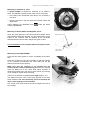
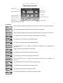
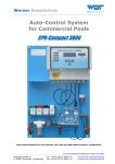
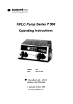
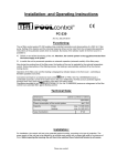
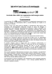
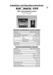
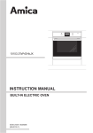
Installation and Operating Instructions
R
-20
Art.No. 3104811211
Function
The electronic backwash controller EUROTRONIK-20 switches the filtration pump of a swimming-pool on
and off at programmable times and controls the backwashing and clear rinsing cycles for cleaning the filter.
The EUROTRONIK, which is mounted on the 6-way valve with a protected quick coupling, automatically
moves the valve into the correct position and operates the filter pump. The time of the backwashing and
clear rinsing cycles is adjustable and can be seen in the LCD display.
The backwashing cycle can be carried out both on a time-control (by way of the integrated digital switch
clock) as well as pressure-dependent basis. The adjustable pressure switch (art. no. 2000599015) is not
included in the delivery package. It is also possible to start the backwashing cycle manually with a key in
the housing cover.
A connection for a 230 V motor-operated valve enables withdrawal of the water needed for the
backwashing cycle directly from the swimming pool instead of from the overflow collecting tank and
replenishment of fresh water during backwashing. An additional floating relay contact can be used
during backwashing to operate a second pump (backwash pump or blower).
A connection for an external temperature regulator provides the possibility of heating the pool during the
filtration times. An internal latch makes sure that the heater will only be enabled when the pump is running.
To empty the swimming pool, the 6-way valve can be moved into the position Empty. The key for this is
also located in the housing cover. For maintenance purposes the valve can also be moved into the
position Closed with a further key.
The respective valve position and position changes can be read on an LCD display in the housing cover
without having to open the housing. The valve disk is lifted before turning to protect the star seal. The
pump is switched off during this time.
Technical specifications
245mm x 140mm x 95mm
Dimensions:
230V/50Hz
Power supply:
Power consumption of the controler:
approx.10VA
Motor-operated valve:
max. 1,1 kW (AC3)
230V
System of protection:
IP 54
Breaking capacity:
Ambient conditions:
0-40°C, max. 95% r.H. non condensing
Usable valves:
Praher 1½" and 2"
Speck 1½" and 2"
Midas 1½" and 2"
Astral 1½"
With appropriate adapter
Astral 2"
Hayward 1½"
Static water pressure:
Water column above the valve:
max.0,3bar
max. 3,0m
Operating instructions EUROTRONIK-20
Page: 2
Table of contents
Seiten
Function
1
Technical specifications
1
Mounting
3
Preparation of the 6-way valve
3
Preparation of the controller
3
Mounting on an Astral 2" valve
4
Mounting on Astral, Midas and Hayward valves
4
Mounting of the EUROTRONIK
4
Electrical connection
5
Operating elements
6
LCD display
6
Switching the controller on/off
7
Manual control of the filter pump
7
Setting the time
7
Programming the timer (backwashing and clear rinsing times)
8
Programming the timer (filtration times)
8
Backwashing (manual)
9
Emptying the swimming pool
9
Closing the valve
9
DIP switch on the upper circuit board
10
Intermittent backwashing
10
Fortnightly backwashing
10
Service terminal (only for service personnel)
11
Operating cycles of the backwash controller
11
Input signals
11
Microswitch
11
Light scanners
11
Heater
11
Filter pump
12
Auxiliary pump
12
Motor-operated valve
12
Servomotor
13
Operating instructions EUROTRONIK-20
Page: 3
Mounting
The controller must be mounted in accordance with its system of protection so that it is protected against
moisture. The ambient temperature should lie between 0° C and + 40° C and should be as constant as
possible. The relative humidity should not exceed 95% and no condensation should occur. Direct incidence
of heat or sunlight on the device must be avoided.
The power supply to the device must be connected via an all-polar main switch with a contact gap width of
at least 3mm. The device must be switched off before the housing is opened.
Shorter osf-pin
Preparation of the 6-way valve
Guide groove
Before mounting the EUROTRONIK it must be ensured that the
valve moves easily and is free of dirt.
The 6-way valve must be in the position Filter when mounting
the controller. In this position the handle of the valve must be
removed by driving the fastening pin out of the valve shaft. Then
insert the shorter osf pin delivered with the device in the middle of
the hole in the valve shaft. If the pin is too loose in the hole, it can
be fastened with a little adhesive or grease to facilitate mounting of
the controller. For later operation of the system it is immaterial
whether the pin is loose because it is centred by the housing of the
controller.
Preparation of the controller
The controller must be in the position Filter (position on delivery).
To equalise height differences of the valve shafts, it is necessary in the case of some valves to stick one or
more of the self-adhesive spacer disks delivered with the device under the housing of the controller.
Proceed as follows to determine whether one or more spacer disks are needed:
Move the 6-way valve into the position Filter.
Mount the EUROTRONIK-10 on the valve without spacer disk.
See "Mounting of the EUROTRONIK".
Push the feeler gauge delivered with the device between the
EUROTRONIK and valve.
If the feeler gauge fits between the EUROTRONIK and valve
exactly, the gap is optimal.
If the EUROTRONIK wobbles on the valve, one or more spacer
disks must be stuck under the EUROTRONIK (see sketch below).
Thereafter the EUROTRONIK must be mounted again and the test
with the feeler gauge repeated.
After mounting the feeler gauge has to be removed. The resultant
play has no negative influence on the operation of the system.
Insert
feeler
gauge
Operating instructions EUROTRONIK-20
Page: 4
Mounting on an Astral 2" valve
A special adapter is needed for mounting on an Astral 2"
valve. This adapter is placed on the valve in such a way that:
• the screws point downwards and catch in the recesses in
the valve.
• the two recesses on the side point to the words "Filter" and
"Backwash".
These adapters are obtainable from
number 1200299200.
under the article
Mounting on Astral, Midas and Hayward valves
Since the guide grooves in the valve bonnets of Midas, Astral
and Hayward valves are narrower, the two yellow slides on the
bottom of the controller must be replaced by the red slides
delivered with the device when using these types of valve.
Replace slides if necessary
It’s not allowable to use an Astral-Valve with bayonet lock!
Stick on spacer
disks if necessary
Mounting of the EUROTRONIK
2
Press the two slides (yellow or red) in completely at the same
time.
1
Place the controller on the valve carefully so that the coupling
of the controller encompasses the valve shaft and the pin
slides into the slot of the coupling.
Make sure that the coupling is not pushed into the
housing of the controller when doing so. Since the coupling
does not always fit on the valve shaft easily because of
dimensional tolerances in the case of some valves, the housing
cover should be closed during mounting.
3
Then turn the actuator completely to the right (approx. 45°).
The slides must then catch in the guide grooves of the valve
when released. The valve shaft may not be turned with the
device when clipping on the controller.
The osf pin in the valve shaft must now be caught in the slot of
the coupling.
1
Operating instructions EUROTRONIK-20
Page: 5
Electrical connection
Only authorised electricians may carry out electrical connection, balancing and service work! The
following connection diagrams and all valid safety regulations must be followed. When working on
the open housing precautions must be taken to protect the electronic components against
electrostatic discharges.
EUROTRONIK-20
T2A
L1 L1 N N N
K1
K4
K2 K3
U2 U3 2
3
4
5
6 7
10 11
P Pressure switch
Backwash pump
230V/max.1,1kW
Mains
230V/50Hz
Temperatureregulator
230V/max.100W
Motor-operated valve
Filter pump
230V/max.1,1kW
All conductive components must be integrated in the local equipotential bonding system.
The terminals L1 and 2, L1 and 3 as well as L1 and 6 have to be connected.
The contact K2 in the EUROTRONIK is closed when the valve has reached one of its final positions. This
prevents the filter pump from being switched on by the filter controller during the adjusting process. In teh
position Filter this contact is only closed during filtration-time.
The contact K3 in the EUROTRONIK is only closed when the valve is in the final position Filter and the
filter pump is running. An external temperature regulator can be connected to terminal 5 which is only
supplied with power during filtration time.
The contact K1 in the EUROTRONIK supplies the terminal U2 with power during backwashing, clear
rinsing and emptying, while for the rest of the time the terminal U3 is live. A motor-operated valve (230 V)
can be connected to these terminals to replenish the water lost during the rinsing cycles.
The contact K4 in the EUROTRONIK is only closed when the valve is in the final position Backwash and
can be used to operate an additional backwash pump.
The osf pressure switch (art. no. 2000599015) can be connected to the terminals 10 and 11. It is screwed
into the manometer connection in the 6-way valve. The metal body of the pressure switch must be
grounded. This switch triggers a backwashing cycle when the pressure limit that has been set is exceeded
irrespective of how the switch clock in the EUROTRONIK has been programmed.
Operating instructions EUROTRONIK-20
Page: 6
Operating elements
LCD display
Manual control of pump
Program timer
(Filtration times)
Controller ON/OFF
Close valve
Backwash (manual)
Empty swimming pool
Set time
Program timer
Change values
(Backwash and clear rinsing times)
LCD display
Thu 8:46
Filter
Normal operating display during filter time showing the current time and valve position.
Thu 9:18
Pause
Normal operating display without filtration showing the current time.
Thu 6:32
Manually
Normal operating display with manually activated filter pump showing the current time.
Lift
Backwash
The backwashing cycle has been started. The valve disk is first lifted.
Rotate
Backwash
The valve disk is turned into the position Backwash.
Lower
Backwash
The valve disk is lowered into the position Backwash.
4:39
Backwash
The backwashing cycle is running. The remaining backwash time is displayed (in
min.:sec.).
Lift
Cl.Rinse
After backwashing the valve disk is lifted again.
Rotate
Cl.Rinse
The valve disk is turned into the position Clear Rinse.
Lower
Cl.Rinse
The valve disk is lowered into the position Clear Rinse.
0:10
Cl.Rinse
The clear rinsing cycle is running. The remaining rinsing time is displayed (in
min.:sec.).
Lift
Filter
The valve disk is lifted to be turned into the position Filter.
Rotate
Filter
The valve disk is turned back into the position Filter.
Lower
Filter
The valve disk is lowered into the position Filter.
Lift
Empty
The valve disk is lifted to be turned into the position Empty.
Operating instructions EUROTRONIK-20
Page: 7
Rotate
Empty
The valve disk is turned into the position Empty.
Lower
Empty
The valve disk is lowered into the position Empty.
The valve is in the position Empty. The filter pump is on.
Pump on
Empty
Lift
Closed
The valve disk is lifted to be turned into the position Closed.
Rotate
Closed
The valve disk is turned into the position Closed.
Lower
Closed
The valve disk is lowered into the position Closed.
Valve
Closed
The valve is in the position Closed. The filter pump is disabled.
Lift
Off
The EUROTRONIK has been switched off. The valve disk is lifted to be turned into the
position Filter (home position).
Rotate
Off
The valve disk is turned into the position Filter (home position).
Lower
Off
The valve disk is lowered into the position Filter (home position).
Machine
is off
The EUROTRONIK is off. The valve is in the position Filter.
Switch
defect
The bottom final position of the valve disk has not been detected. The microswitch in
the bottom part of the housing is possibly damaged. When the fault has been repaired,
the controller can be switched off and back on again with the key .
Switching the controller on/off
The controller is switched on and off with the key . Note! This does not switch off the power
supply to the device! If the valve is not in the position Filter when the controller is switched
off, it is turned there automatically.
Manual control of the filter pump
The can be switched on manually with the key
.
Setting the time
The time and weekday are set with the key
1. Press the key
:
Mon 8:46
⇒ time
appears in the display.
2. The time can then be set with the keys
and
.
To save the time, press the key
again. If, during setting, more than 10 seconds pass
without a key being pressed, the last time displayed is saved automatically and the normal
operating display appears again.
Operating instructions EUROTRONIK-20
Page: 8
Programming the timer (backwashing and clear rinsing times)
The integrated weekly timer for automatic backwashing and clear rinsing is programmed with
the key :
1. Press the key
Duration
120 appears in the display.
Back:
⇒
2. The desired duration of backwashing (in seconds) can then be set with the keys
and
. The maximum backwashing time that can be set is 900 seconds (15 minutes). If a
backwashing time of 0 seconds is set, the timer is inoperative.
3. Press the key
Duration
10 appears in the display.
Clear
again ⇒
4. The desired duration of clear rinsing (in seconds) can then be set with the keys
The maximum clear rinsing time that can be set is 120 seconds (2 minutes).
5. Press the key
-------1.Rinse
again ⇒
and
.
appears in the display.
6. The desired point in time for backwashing can then be set with the keys
and
.
7. Further backwashing cycles can then be programmed as described in points 5 and 6. A
total of 15 backwashing cycles per week can be programmed.
8. To save the switch times, press the key
again. If, during setting, more than 10 seconds
pass without a key being pressed, the last switch time displayed is saved automatically
and the normal operating display appears again.
If backwashing times have already been programmed, they can be deleted with the key
1. Press the key
display
:
repeatedly until the backwashing time that is to be deleted appears in the
Wed 9:00
2. Rinse
-------2.
Rinse
2. Set the backwash time on
with the keys
and
(between Sun. 23:59 and
Mon. 0:00).
3. To delete the switch time, press the key
again.
Programming the timer (filtration times)
The integrated weekly timer for the filter pump is programmed with the key
1. Press the key
-------⇒ 1. ON
:
appears in the display.
2. The desired beginning of the first filtration time can then be set with the keys
3. Press the key
and
.
Mon 0:00
1.
OFF
again ⇒
appears in the display.
4. The desired end of the first filtration time can then be set with the keys
-------2.
EIN
5. Taste
erneut drücken ⇒ in der Anzeige erscheint
and
.
6. Further filtration times can then be programmed as described in points 2-5. A total of 15
filtration times per week can be programmed.
7. To save the switch times, press the key
again. If, during setting, more than 10 seconds
pass without a key being pressed, the last switch time displayed is saved automatically
and the normal operating display appears again.
If filtration times have already been programmed, they can be deleted with the key
1. Press the key
:
repeatedly until the filtration time that is to be deleted appears in the
Operating instructions EUROTRONIK-20
Page: 9
Wed 7:30
display 3. ON
-------3.
ON
2. Set the filtration time on
with the keys
and
(between Sun. 23:59 and
Mon. 0:00).
3. To delete the switch time, press the key
again.
Backwashing (manual)
A backwashing cycle can be started manually at any time – irrespective of how the timer has
been programmed – with the key . The duration of the backwashing cycle is the same as
that entered during programming of the timer.
This key can also be used to end a backwashing cycle already in progress.
Emptying the swimming pool
When the key
is pressed for longer than 5 seconds, the valve is turned into the
position Empty and the filter pump switched on. Emptying can be stopped by pressing this
key again.
Closing the valve
The key
is used to turn the valve into the position Closed for service purposes. In this
valve position the filter pump is disabled. The valve is turned back into the position Filter by
pressing this key again.
Operating instructions EUROTRONIK-20
Page: 10
DIP switch on the upper circuit board
Intermittent backwashing and fortnightly backwashing can be activated with a DIP switch on the upper
circuit board inside the EUROTRONIK. The housing has to be opened to access these operating
elements.
The power supply to the device must be switched off first! Since the interior of the EUROTRONIK
contains electronic components that react sensitively to the discharging of static electricity, the
tools used must first be discharged by touching a grounded metal part. The electronic components
should not be touched as far as possible.
ON
Fortnightly backwashing
intermittent backwashing
Intermittent backwashing
The EUROTRONIK-10 offers two possibilities of controlling the filter pump during backwashing:
a) Constant backwashing with continuous operation of the filter pump during the complete backwashing
time.
b) Intermittent backwashing with repeated switching on and off of the pump during the backwashing time
for better loosening of the filter sand.
The right switch in the DIP switch is used to switch between intermittent backwashing and constant
backwashing. The bottom switch position is for constant backwashing (factory setting) and the top switch
position for intermittent backwashing.
Fortnightly backwashing
If, in the case of pools subject to little use, a backwashing cycle is only to be started every second week,
the left switch in the DIP switch must be switched into the top switch position. If it is in the bottom switch
position (factory setting), every switch command of the switch clock is carried out. In the top switch position
only one backwashing cycle per week can be programmed with the switch clock. This backwash command
is only carried out every second week.
Operating instructions EUROTRONIK-20
Page: 11
Service terminal (only for service personnel)
ON
An osf service terminal (art. no. 3010000900) can be connected to
this controller for optimum adjustment of the controller to the
different types of swimming pool and to facilitate commissioning
and fault diagnosis. The connector for this is mounted on the circuit
board inside the device. The power supply to the controller
must be switched off before opening the housing and
plugging in the service terminal! Plugging the service
connector in or out when the device is on can destroy the
device! The operating time meter appears in the display of the
service terminal after switching on the controller, e.g.:
connector for service terminal
Further pages can be called up with the keys
changed after pressing the key .
Operating hours:
total:
238
switched on 156
Filt.-pump
26
and
. If necessary, the values in the top line can be
Operating cycles of the backwash controller
The following counter statuses are shown:
Backwash
Number of completely carried-out backwash cycles.
Empty
Number of emptying cycles.
Close
Number of closing cycles.
Input signals
The current input signals of the EUROTRONIK are shown in this line:
Pressure switch:
Switch status of a pressure switch connected to terminals 10 and 11.
B. fortnightly:
Switch position of the left DIP switch (backwash fortnightly).
B. interval:
Switch position of the right DIP switch (intermittent backwashing).
Microswitch
The current status of the microswitch in the bottom part of the housing, which is used by the controller to
detect whether the valve disk has been lowered, is shown on this page.
Light scanners
The measured values of the light scanners, which are used by the controller to detect the valve positions,
are shown on this page. Two values are shown for each of the five light scanners. The value in brackets
should be between 30 and 70. The other value should be more than 700 when the housing is open and
should fall notably on approaching a reflecting object.
The following lines enable the service technician to check the output relays of the controller.
Heater
This line shows whether the relay K3 is on. This relay is used to activate the heater while the filter pump is
on.
The following displays are possible:
Heater: OFF
The relay contact between terminals 3 and 5 (K3) is open, the heater is
disabled.
Heater: On
The relay contact between terminals 3 and 5 (K3) is closed, operation of the
heater is enabled.
When the heater is shown in the top line of the service terminal, it can be switched on or off:
Operating instructions EUROTRONIK-20
1. The following display appears after pressing the key
Page: 12
:
Heater:
OFF
Manual control
of contact betw.
terminals 3+5.
(K3 closed) and disabled again with the key
2. The heater can be enabled with the key
3. The normal diagnostics display reappears when the key
is pressed again.
(K3 open).
Filter pump
This line shows whether the relay K2 is on. This relay is used to switch the filter pump on or off.
The following displays are possible:
Filtration: OFF
The filter pump is switched off (K2 open)
Filtration: ON
The filter pump is switched on (K2 closed)
When the filter pump is shown in the top line of the service terminal, it can be switched on or off:
1. The following display appears after pressing the key
:
Filtration:
OFF
Manual control
of contact betw.
terminals 2+4.
(K2 closed) and switched off again with the key
2. The filter pump can be switched on with the key
(K2 open).
3. The normal diagnostics display reappears when the key
is pressed again.
Auxiliary pump
This line shows whether the EUROTRONIK switches on an auxiliary backwash pump with the help of the
contact K4.
The following displays are possible:
Backw.pump: OFF
The pump is off (K4 open).
Backw.pump: ON
The pump is on (K4 closed).
When the auxiliary backwash pump is shown in the top line of the service terminal, it can be switched on
or off:
1. The following display appears after pressing the key :
Backw.pump: OFF
Manual control
of contact betw.
terminals 6+7.
2. The backwash pump can be switched on with the key
key
(K4 open).
3. The normal diagnostics display reappears when the key
(K4 closed) and switched off again with the
is pressed again.
Motor-operated valve
This line shows whether a motor-operated valve is opened or closed by the relay contact K1.
The following displays are possible:
Motor valve:SHUT
The motor-operated valve is closed, terminal U3 is live with mains power.
Motor valve:OPEN
The motor-operated valve is open, terminal U2 is live with mains power.
When the motor-operated valve is shown in the top line of the service terminal, it can be opened or closed:
1. The following display appears after pressing the key
:
Motor valve:SHUT
Manual control
of motorvalve on
terminals U2+U3
2. The motor-operated valve can be opened with the key
and closed again with the key
3. The normal diagnostics display reappears when the key
is pressed again.
.
Operating instructions EUROTRONIK-20
Page: 13
Servomotor
This line shows whether the servomotor in the EUROTRONIK to turn the 6-way valve is on or off.
The following displays are possible:
Act.motor: OFF
The servomotor is off.
Act.motor: UP
The servomotor lifts the valve disk or turns it into the next position.
Act.motor: DOWN The servomotor lowers the valve disk.
When the servomotor is shown in the top line of the service terminal, it can be switched on or off:
1. The following display appears after pressing the key
:
Act.motor: OFF
Manual control
of drive
(6-way-valve)
2. The valve disk can be lifted and turned with the key . Renewed pressing of the key
switches the
servomotor off again.
3. The valve disk can be lowered into one of the valve positions with the key . The motor is switched off
when the bottom final position is reached or the key is pressed again.
4. The normal diagnostics display reappears when the key
is pressed again.
Note!
The drain of the swimming pool must be installed in such a way that the pipe is
higher than the water level at least at one point. A suitable ventilation valve must
be installed at the highest point. The function of this ventilation valve is to
ventilate the drain pipe whenever the filter pump is not in operation. This then
prevents unnecessary water loss in the event of a leaking multiple-way valve.
These installation and operating instructions must be observed.
We wish you lots of fun and relaxation in your swimming pool.
Subject to changes!
6. August 2015