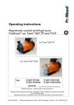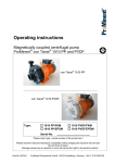
1
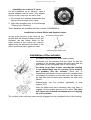
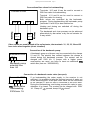
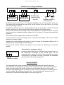
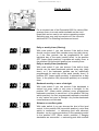
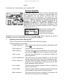
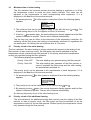
Installation- and Operating Instructions
-2000
Filter- and backwash control
With connections for bar valves
Item no.: 3105500200
Technical specifications control system:
Dimensions:
325mm x 280mm x 160mm
Operating voltage:
400V/50Hz
Power consumption of control system:
Breaking capacity:
Approx. 15VA
Pump:
max. 3.0 kW (AC3)
Heating:
max. 0.4 kW (AC1)
Dosing equipment:
max. 0.4 kW (AC1)
Additional output:
Protection type:
Level sensors
max. 3A (AC1)
IP 40
12V AC
Technical specifications actuator:
Dimensions:
Operating voltage:
Protection type:
Useable six-port valves:
245mm x 140mm x 95mm
24V/50Hz
IP 54
Praher 1½" and 2"
Speck 1½" and 2"
Midas 1½" and 2"
Hayward 1½"
Astral 1½"
With applicable adapter
Static water pressure:
Water column above valve:
Astral 2”
max.0.3bar
max. 3.0m
Operating Instructions Euromatik-2000
Page: 2
Table of Contents
Function: ............................................................................................................................................... 3
Installation: ........................................................................................................................................... 4
Preparation of the six-port valve:..................................................................................................................4
Preparation of the EUROMATIK actuator: ................................................................................................4
Installation on an Astral 2” valve ..................................................................................................................5
Installation on Astral, Midas and Hayward valves .....................................................................................5
Installation of the actuator: .................................................................................................................. 5
Electrical connection: ........................................................................................................................... 6
Mains supply for use of a 400V three-phase current pump: ......................................................................6
Mains supply for use of a 230V alternating current pump: .......................................................................6
Connection of the heating: .............................................................................................................................7
Connection of the EUROMATIK actuator for the six-port distributing valve: .......................................7
Operation of the control system without EUROMATIK actuator: ..........................................................7
Connection of the backwash pump: ..............................................................................................................8
Connection of a backwash motor valve (two-port): ....................................................................................8
Additional connecting possibilities: ...............................................................................................................9
Connection of a press key: .............................................................................................................................9
Level control:......................................................................................................................................... 9
Swimming pools with flow-off gutter ..........................................................................................................10
Application for outdoor swimming pools: ..................................................................................................10
Notice of function of the level control for receivers: .................................................................................11
Swimming pools with skimmer: ..................................................................................................................11
Application without level control ................................................................................................................12
Magnetic valve water backfeed ...................................................................................................................12
Temperature sensor: ........................................................................................................................... 12
External control panel: ....................................................................................................................... 13
Control elements on the front plate: .................................................................................................. 13
Adjusting of temperature control: ...................................................................................................... 17
Fuses: .................................................................................................................................................. 18
Electronic motor protection:............................................................................................................... 18
Code switch: ........................................................................................................................................ 19
Daily or weekly timer (filtering) ..................................................................................................................19
Daily or weekly timer (backwash) ...............................................................................................................19
Backwash weekly or once a fortnight .........................................................................................................19
Skimmer or overflow gutter.........................................................................................................................19
Service terminal: ................................................................................................................................. 20
Operating Instructions Euromatik-2000
Page: 3
Function:
The
control Euromatik-2000 enables a time-dependent switching on- and off of a
400V three-phase current filter pump or a 230V alternating current filter pump by using a
freely programmable daily or weekly programme.
The backwash may be carried out manually, time-dependent or pressure-dependent.
The integrated level control is suited for swimming pools with overflow gutter (receiver) and
for skimmer pools.
The filter control can be remote controlled by an external control element.
During the run time of the filter pump, the heating of the pool is controlled by the electronic
temperature control. During the filter pauses the heating is automatically switched off by the
internal locking. Due to the given possibility to connect a safety temperature limiter or a flow
monitor, the heating is additionally protected against overheating. On the front plate the
requested temperature of the pool water can be selected, or the heating can be switched
off. For the connection of the heating both a living contact (clamp U2) and a floating contact
(clamps 23 + 24) are available. For the solar collector operation there are terminal clamps
available to be used for a
solar actuator.
Terminal clamps for level sensors enable a comfortable, automatic control of the water
level in the swimming pool. Additional terminal clamps allow to connect a flow monitor or a
press key. Thus the filter pump is addtionally protected against damages that could be
caused if the filter system was operated without water.
Additional terminal clamps allow to connect accessory devices such as e.g. underwater
floodlights and dosing equipment. A consumer (230V/max. 3A) connected to clamp U4 may
be switched on- and off at will with a key placed in the front lid. The clamp U3 only leads
230V during the filter periods, off the filter periods it is floating. The clamps 25+26 are
floating and thus may be used individually. During the filter periods the relay contact
between clamp 25 and 26 is closed, off the filter period this relay contact is open. This
contact can be charged with a maximum voltage of up to 230V and a maximum force of up
to 400W (cos ϕ=1).
Clamps 19+20 are potential free and can be used for error messages.
The terminal clamps for the protective winding contact allow to connect a protective winding
contact switch that is integrated in the motor winding of the filter pump. If this contact
opens, e.g. due to overheating of the motor winding, both the filter pump as well as the
heating and the dosing equipment are also automatically switched off. As soon as the
protective winding contact closes after cooling of the motor winding, the aggregates are
switched on again automatically. A manual reset is not necessary. The terminal clamps for
the protective winding contact are charged with 230V.
Terminal clamps for a remote switch offer the possibility to remote control the filter system.
The 24 V actuator is connected to the control unit by a 6-core line.
Backwashing can be done alternatively by 6-way valve or by bar valves.
The operation of the filter pump and the heating is indicated by pilot lights in the front lid –
so a check is possible at any time.
The filter pump is protected against overload by an electronic motor protection (current
range continuously adjustable up to 8A).
Operating Instructions Euromatik-2000
Page: 4
Installation:
The control unit has to be installed humidity protected, depending on its protection type.
The power supply of the device has to be effected by an all-pole main switch having a
contact opening of at least 3mm and an earth leakage circuit breaker with IFN≤ 30mA.
Before opening the housing it is absolutely necessary to switch the device to zero
potential.
Preparation of the six-port valve:
Prior to the installation of the EUROMATIK
actuator you have to ensure that the valve
runs smoothly and is absolutely free of dirt.
shorter osf bolt
guide groove
On installing the actuator the six-port valve
must be in position Filtering. In this position
the handle of the valve must be removed by
starting the mounting bolts out of the valve axis.
Subsequently you have to centrally insert the
delivered shorter osf bolt into the borehole of the
valve axis. If the bolt is too loose inserted in the
borehole, it may be fixed with some glue or
grease to facilitate the installation of the
actuator.
For the subsequent functioning of the equipment it is of no importance if the bolt is
loose as it will be centered by the housing of the actuator.
Preparation of the EUROMATIK actuator:
The actuator must be in position Filtering. (condition on delivery).
In order to even out height differences of the valve axis with some valves, you have to glue
one or more of the delivered self-adhesive distance shims under the housing of the control
unit.
The determination of the distance shims is carried out as follows:
Place six-port valve in position Filtering.
Install actuator without distance shim onto the
valve. See ”Installation of the control unit”.
Put enclosed thickness gauge between actuator
and valve.
The distance is optimal, if the thickness gauge fits
exactly between actuator and valve.
If the actuator is loose on the valve, one or more
distance shims are to be glued under the actuator
(see sketch below).
Afterwards the actuator is to be installed again and
you have to repeat the thickness gauge test.
After the installation has been carried out you have to remove the thickness gauge. The
arising following looseness will not negatively influence the function of the equipment.
Operating Instructions Euromatik-2000
Page: 5
Installation on an Astral 2” valve
For the installation on an Astral 2” valve a
special adapter must be used. This adapter
is put in such a way onto the valve, that:
1. the screws are inserted downwards and
grip into the recesses of the valve.
2. both side recesses point to the letterings
”Filtering” and ”Draining”.
These adapters are available with item number 1200299200 at .
Installation on Astral, Midas and Hayward valves
If necessary, exchange slides
As the guide grooves in the valve lid are
smaller with the valves of Midas, Astral and
Hayward, the two yellow slides on the
lower surface of the control unit must be
replaced by the delivered red slides, if the
above mentioned valve types are used.
if necessary, glue distance shim
Installation of the actuator:
Simultaneously press both slides totally inward.
Cautiously put the actuator onto the valve so that the
coupling of the actuator encloses the valve axis and the
bolt slides into the elongated hole of the coupling.
On doing so you have to take care that the coupling
is not pushed-back into the housing of the actuator
and probably lifts the actuator. Since due to
dimensional tolerances of some valves the coupling does
not always fit smoothly on the valve axis, the shim must
be held with both thumbs when locating the shim (see
sketch).
Subsequently turn the actuator rightwards to stop
(approx. 45°).
After the slides have been released, they now have to
engage into the guiding grooves of the valve. The valve
axis must not be turned simultaneously on snapping
on of the actuator.
The osf bolt in the valve axis now must be engaged into the elongated hole of the coupling.
Operating Instructions Euromatik-2000
Page: 6
Electrical connection:
The electrical connection as well as any adjustment and service work may only be
carried out by an accredited electrical specialist! The enclosed connecting diagrams
and the prevailing corresponding safety regulations are to be observed.
Mains supply for use of a 400V three-phase current pump:
Euromatik-2000
17 18 15 16 W1 V1 U1
L3 L2 L1 N
Pre-fuses
max. B16A
M
Protective
winding
3
Filter pump
400V max. 8A
FI-switch
25A/0,03A
Mains 3/N/
400/230V 50Hz
The factory-provided inserted bridge between the clamps 15 and 16 must be removed if a
pump with protective winding contact is connected. If no connection is carried out, it needs
to be screwed in. The clamps lead mains voltage!
Instead of the factory-provided bridge inserted between clamps 17 and 18, it is possible to
connect a flow monitor or a pressure controller to additionally protect the pump against dryrunning. In case of filter operation this contact has to be closed at the latest 10 seconds
after starting of the filter pump, otherwise the filter pump is switched off and the error
message light flashes. In the backwash operation this contact is not interrogated. The
clamps lead mains voltage!
Mains supply for use of a 230V alternating current pump:
Euromatik-2000
17 18 15 16 W1V1 U1 N
Protective
winding
M
1
Filter pump
230V max. 8A
L3 L2 L1 N
Pre-fuses
max. B16A
FI-switch
25A/0,03A
Mains 1/N/
230V 50Hz
So that the electronic motor protection works properly, the motor current must be led via all
three contact points of the filter control (clamps L2 and L3 as well as U1 and V1 bridged,
pump connected to W1).
Operating Instructions Euromatik-2000
Page: 7
The factory-provided inserted bridge between the clamps 15 and 16 must be removed, if a
pump with protective winding contact is connected. If no connection is carried out it needs
to be screwed in. The clamps lead mains voltage!
Instead of the factory-provided bridge inserted between clamps 17 and 18 it is possible to
connect a flow monitor or a pressure controller to additionally protect the pump against dryrunning. In the filter operation this contact must be closed at the latest 10 seconds after the
filter pump has started; otherwise the filter pump is switched off and the error message light
flashes. This contact is not interrogated in the backwash operation. The clamps lead mains
voltage!
Connection of the heating:
Euromatik-2000
N U5 U6
U2 N 23 24
Heating
Potential free
max. 4A
Heating 230V
max. 400W
N 6 2
Solar
actuator 230V 1A
For the operation of the solar heating it is possible to connect a 230V
solar actuator to
the clamps U5 and U6. When solar operated clamp U6 leads mains voltage and clamp U5
is voltage free. If the solar heating is not operated, clamp U6 is voltage free and clamp U5
leads mains voltage.
Connection of the EUROMATIK actuator for the six-port distributing valve:
For the connection of the actuator the enclosed six-pole
connecting line with plug is to be used. If connected to the
control unit, the poles must not be exchanged.
Operation of the control system without EUROMATIK actuator:
If the control is to be operated without actuator, the connecting terminals 31, 32, 33, 34 und
35 are to be connected (bridged). The connecting line is disconnected before.
Operating Instructions Euromatik-2000
Page: 8
Connectionof bar valves for backwashing:
Terminals U10 and N can be used to connect a
230V bar valve for backwashing.
EUROMATIK-2000
Terminal U11 and N can be used to connect a
230V bar valve for rinseing.
U11 N
U10 N
Both valves are controlled by the backwashprogram. During backwashing the backwash pump
(terminals 21 and 22) is also switched on.
Heating and dosing are switched off during the
backwash cycle.
230V
230V
max.1A
max.1A
The backwash and rinse process can be achieved
alternatively by bar valves or by the osf actuator for
6-way valves.
If bar valves are used instead of the osf actuator, the terminals 31, 32, 33, 34 and 35
have to be wired together (short circuited)
Connection of the backwash pump:
Euromatik-2000
21 22
Backwash pump
potential free
max. 4A
A backwash pump or a blower may be connected to the clamps
21 and 22. The ptential free contact between the clamps is
closed during the backwash process. The contact can be
charged with 230V 4A. If pumps with a higher power
consumption are used, you have to insert an additional
switch box (item no.: 3002400000).
Connection of a backwash motor valve (two-port):
Euromatik-2000
U7U8 N
-Motor valve
backwashing
230V/max. 1A
If on backwashing the water supply in the receiver is not
sufficient, it is possible to take the required amount of water out
of the swimming pool. A two-port motor valve can be connected
to the clamps U7 and U8 that is connected to the floor drain.
During the backwashing- and rinsing process this valve is open,
otherwise it is closed. The contact can be charged with 230V
1A. Clamp U7
opened, clamp U8
closed
Operating Instructions Euromatik-2000
Page: 9
Additional connecting possibilities:
Euromatik-2000
U4 N
L1 N
Accessory dev.
230V max.3A
U3 N
25 26
L1 N
Dosing equip.
230V max.3A
Dosing equip.
(potential free)
max.4A
7 8 9 10
Pump
Pump
ON
OFF
Remote control or
pool covering
A 230V accessory device (e.g. an underwater floodlight) may be connected to clamp U4.
This device can be switched on and off at will by using a key in the front lid (or on the
external operating element).
An additional 230V device (e.g. dosing equipment) may be connected to clamp U3. During
the filter operation this device can be switched on together with the filter pump.
In the control unit there is a floating relay contact between the clamps 25 and 26. It can be
used to control an additional dosing equipment (in this case it is closed during the filter
operation).
This contact can be charged with a maximum of 230V/4A.
A remote switch or the pool covering can be connected to the clamps 7, 8, 9 and 10. These
clamps drive mains voltage!
Opening the contact between the clamps 9 and 10 causes an immediate switching off of
the filter pump, dosing equipment and heating.
Closing of the contact between the clamps 7 and 8 causes a switching on of the filter
system.
Connection of a pressure switch:
Euromatik-2000
37 38
24V
Pressure switch
A pressure switch that can be installed in the pressure line or in
the manometer connection of the central valve, can be
connected to the clamps 37 and 38. If the potential free contact
of the press key is closed for at least 10 seconds, the backwash
process starts. The clamps supply 24V.
Level control:
The integrated level control is suited for both swimming pools with flow-off gutter and
skimmer pools. On putting into operation of the control you have to choose the requested
option. On the board of the control unit there is a code switch where you can set the
corresponding operating mode. On delivery switch 4 of the code switch is in switch position
”receiver control”. By switching to position ”on”, the operating mode ”skimmer pool” is
switched on. Please find a sketch below in the text on page 19.
Operating Instructions Euromatik-2000
Page: 10
Swimming pools with flow-off gutter
Euromatik-2000
43 44 45 46 47
Forced switching on
max.
min.
TRS
Mass
dipped electrodes are to be used as
sensors. The tensile stress of the line is
sufficient to hang the electrodes into the
flow-off collecting receiver by means of the
special line
whereas
the
individual
electrodes may contact each other. The
fixing is carried out above the receiver by
using the
electrode holding device. The
special lines are brought together in a
customer-provided and installed branch box.
2
A line (e. g. NYM-0 5x1.5 mm ) is layed from
this branch box to the control unit.
On connecting the dipped electrodes you have to take particular care that the order is not
mixed up since a mixing-up of the electrodes will inevitably cause a malfunction of the
equipment.
Application for outdoor swimming pools:
According to the designed concept of the swimming pool, it may occur that in outdoor
swimming pools rainwater can raise the water level thus activating the function ”forced
switching on”. If this operation is not requested, the electrode ”forced switching ON” (clamp
47) can be disconnected. All remaining dipped electrodes are necessary for the function of
the control and cannot be dropped and must not be bridged respectively.
Fonction of the particular dipped electrodes
Forced switching on ON
Double fonction:
Forced switching OFF
Magnetic valve CLOSED
Double fonction:
Magnetic valve OPEN
Dry-running protection: Pump ON
Dry-running protection: Pump OFF
Mass
In normal operation
the water level is
between the
electrodes ”magnetic
valve CLOSED” and
”magnetic valve
OPEN”
The differences in
level depend on
individual
circumstances. In
order to get sufficient
switch intervals, you
have to ensure 5 cm
at a minimum.
Operating Instructions Euromatik-2000
Page: 11
Notice of function of the level control for receivers:
The level control for receivers has the following functions:
a)
Control of the water level.
If due to loss of water in the swimming pool, e.g. caused by evaporation or
backwashing, the water level falls below the dipped electrode ”magnetic valve OFF”
(clamp 45), the magnetic valve (clamp U9) opens and the flooding fresh water causes
an increase of the water level. As soon as the rising water level has reached the
position of the dipped electrode ”magnetic valve OFF” (clamp 46) and has contacted
the relevant electrode, the magnetic valve closes the supply of fresh water.
b)
Dry-running protection of the filter pump.
If due to loss of water in the receiver, e.g. caused by backwashing, the water level
falls below the dipped electrode ”dry-running protection pump OFF” (clamp 44), the
level control switches off the filter pump so that it is not damaged by lack of water. As
soon as the water level has risen up to the height of the electrode ”dry-running
protection pump ON” (clamp 45), and has contacted said electrode, the level control
automatically switches on the filter control again.
c)
Forced switching on.
If, due to water displacement in the swimming pool, the water level in the receiver
rises and contacts the dipped electrode ”forced switching ON” (clamp 47), the level
control automatically switches on the filter pump. Now the water is pumped back into
the swimming pool thus avoiding unnecessary loss of valuable water. The dipped
electrode ”forced switching ON” is to be placed some centimeters below the overflow.
Swimming pools with skimmer:
Euromatik-2000
43 44 45 46 47
A
mini float switch is to be used as
sensor. The line of the float switch can be
lengthened to up to 100m with a line
(2x0.75mm²). Please note, that it is
absolutely
necessary
to
carry
out
connections waterproof. The connecting line
of the float switch should not be layed
together with other live lines.
float switch
In connection with the mini float switch, a time delay is automatically activated in this
operating mode. This variable time delay prevents too many switching processes that could
be caused by wave motions of the pool water. The time delay may be extended or
shortened by means of a
- service terminal. For this also see further below in the text
under ”service terminal”.
Operating Instructions Euromatik-2000
The mini float switch is mounted on the
sliding angle. Then the fastening bar is
vertically fixed at the inner skimmer wall,
roughly at the height of the requested water
level. The water level can be selected by
moving the sliding angle in the fastening bar.
The sliding angle is then fixed by screwing in
the screw. All parts easily fit into one another
making use of force unnecessary.
Page: 12
Skimmer wall
connecting
lines
screw
slide
angle
floater switch
schalter
Water level
floater
retaining ring
fixation bar
Application without level control
If the integrated level control is not used, the
clamps 43,44,45 and 46 must be
interconnected.
Euromatik-2000
43 44 45 46 47
Magnetic valve water backfeed
A currentless closed magnetic valve is to be used for the water supply. This is connected to
clamp U9 at the control unit. A damped closing magnetic valve (R½”) is available with item
number 1090005804 from the
product range.
Temperature sensor:
-Immersion sleeve
Euromatik-2000
39 40
41 42
Temperature sensor
pool
Solar
sensor
The pool temperature sensor is connected to the clamps 39 and 40. As a standard, the
temperature sensor is delivered with a cable length of 1.5m. If required, it can be
lengthened with a two-core cable (cross section min. 0.5mm²) up to a maximum of 20m. It
Operating Instructions Euromatik-2000
Page: 13
should be avoided to lay the sensor cable near power lines to exclude possible
disturbance.
As an exact temperature control is only carried out with a good heat transfer between the
temperature sensor and the pool water, an
immersion sleeve R 1/2 " (item no.
3200200003) is to be installed into the piping system.
Any polarity of the sensor is possible.
A solar temperature sensor (item no. 3100000030) may additionally be connected to the
clamps 41 and 42. As a standard, the temperature sensor is delivered with a cable length
of 20m. If required, it may be lengthened with a two-core cable (cross section min. 0.5mm²)
up to a maximum of 50m. It should be avoided to lay the sensor cable near power lines to
exclude possible disturbance. The solar temperature sensor is to be installed at the output
of the solar collector and must have a good thermal contact to the back-flowing water.
External control panel:
An external control panel can be connected in-wall
(item no. 3100000420) or on-wall (item no.
3100000410) to the clamps 48-51. A four-core
telephone cable (item no. 3100000500) with a length
of max. 50m is used for the connection to the
backwash control. It should be avoided to lay the
connecting cable near power lines to exclude
possible disturbance.
Euromatik-2000
48 49 50 51
35 36 37 38
External control panel
Control elements on the front plate:
LCD
23,4 °C
LCD
23,4 °C
14:46
After-run
Normal operation display with current water temperature
and time.
The filter pump continues to run for a short time after the
heating has been switched off.
Operating Instructions Euromatik-2000
Page: 14
LCD
Forced swit. on 13:37
The filter pump has been switched on by the integrated
level control.
LCD
Lack of water
The filter pump has been switched off by the integrated
level control.
LCD
Level sensor defect
LCD
Pump locked
13:59
The level sensors have not been properly connected or the
order has been mixed up.
13:37
The filter pump has been switched off by the protective
winding contact or by a remote switch connected to the
clamps 9 and 10.
The filter pump has been switched off by the electronic
motor protection. To switch on the pump again, the key
must be pressed after the pump has cooled.
LCD
Pump overloaded!
LCD
Pump does not deliver! The filter pump has been switched off by the press key
connected to the clamps 17 and 18 or by the flow monitor.
To switch on the pump again, the key
must be pressed
after the error has been cleared.
LCD
Net phase missing!
LCD
Sensor defect
The filter pump has been switched off because there is no
current in all three phases of the three-phase current
network. To switch on the pump again, the key
must
be pressed after the error has been cleared.
13:37
The temperature control is out of operation because the
temperature sensor is not connected or is defect.
LCD
Turn backwash
The actuator turns in the direction of backwash.
LCD
Remain.backwash8 s
The actuator is in valve position backwash.
LCD
Turn rinsing
The actuator turns in the direction of rinsing.
LCD
Remain.rinsing 5 s
The actuator is in valve position rinsing.
LCD
Turn filtering
The actuator controls valve position filtering.
LCD
Turn draining
The actuator turns in the direction of draining.
LCD
Draining
The actuator is in valve position draining.
Control ON/OFF
Manual operation
Acknowledge
error message
With this key the entire control unit can be witched on and –
off. Attention! By pressing this key, the control unit is not
switched to zero potential! If the control unit is switched on,
this key flashes.
With this key the filter pump can be switched on manually,
regardless of the timer. The key flashes in case of manual
operation.
If the control detects an error (e. g. motor protection) this key
flashes in red. This error message must be acknowledged by
pressing this key, so that the normal operation of the
Operating Instructions Euromatik-2000
Page: 15
equipment can be continued.
Additional output With this key an additional output (clamp U4, 230V) is
controlled, that can for instance be used to switch an
ON/OFF
underwater floodlight. The key flashes if the consumer is
switched on. The function of the additional output is not
interlocked with the filter pump.
Pilot light pump
This pilot light indicates the operation of the filter pump.
Pilot light heating
This pilot light flashes if the heating (additional heating) is
switched on.
Pilot light
heating
Select
temperature
solar This pilot light flashes if the solar heating is operating.
With this key the temperature of the pool water is selected:
1. Press
key ⇒ the display indicates
23,4 ° Nominal temp.
2. With the keys
and
the requested temperature within
the range of 0.1°C up to 40°C can now be set.
3. If the heating is to be completely switched off, you have to
reduce the temperature with the key
as long as the
Heating
switched
OFF
display indicates
.
4. To save the requested temperature, press the key
again.
If on setting the temperature no key is pressed for more
than 10 seconds, the last selected temperature is
automatically saved and the normal operation display
appears again.
If a solar sensor is connected to the control, the current
temperature of the solar sensor can be displayed with this key:
1. Press
key twice ⇒ the display indicates the temperature
at the solar sensor, e. g. 32,8 ° Solar sensor .
2. To close this display, press the key
again. If no key is
pressed for more than a minute, the normal operation
display automatically appears again.
Setting time
With this key the current time is set:
14:26 . If
1. Press
key ⇒ the display indicates Time:
the timer is operated as a weekly timer, the corresponding
day of the week is additionally displayed.
2. Now you can set the current time by using the keys
.
and
3. To save the time, press the key
again. If on setting no
key is pressed for more than 10 seconds, the last displayed
time is automatically saved and the normal operation
display appears again.
Operating Instructions Euromatik-2000
Programming
timer
Page: 16
With this key the built-in timer is programmed whereas the
switch on time and the corresponding switch off time always
have to be entered in pairs:
1. Press
key ⇒ the display indicates 1. Pump ON: --:-- . If the
timer is operated as a weekly timer, the corresponding day
of the week is also displayed. Switching over from daily to
weekly timer, see further below in the text on page 19.
2. With the keys
set.
and
key
3. Press
1. Pump OFF
the requested switch on time can be
again
⇒
the
display
indicates
0:00
4. Now the requested switch off time can be set with the keys
and .
5. Press
key
2. Pump ON:
again
⇒
the
display
indicates
--:--
6. Additional switch times can now be programmed as
described in points 2 to 5.
7. To save the times, press the
key again. If on setting no
key is pressed for more than 10 seconds, the last displayed
time is automatically saved and the normal operation
display appears again.
Deleting switch times:
If switch times have already been programmed, they can be
deleted with the key
:
1. Press
as long as the display indicates the switch time
that is to be deleted 2. Pump ON: 8:25
2. With the keys
2. Pump ON:
--:--
and
set the switch on time
(between 23:59 and 0:00).
3. To delete the switch time, press the
again – the
corresponding switch off time is also automatically deleted.
+
Adjusting
keys
With these keys you can program the water temperature, time,
switch- and backwash time.
Backwash manual With this key the backwash process is started manually. If a
backwash time of 0 seconds has been set, the backwash
process does not start. If a clear rinsing time of 0 seconds has
been preset, the valve position ”rinsing clear” is not run.
Setting backwash With this key the backwash- and rinse time is programmed:
time
1. Press key ⇒ the display indicates 300 s Backwashing .
2. Now the requested backwash time can be set with the keys
and .
3. Press
key again ⇒ the display indicates
30 s Clear rinsing
Operating Instructions Euromatik-2000
Page: 17
4. Now the requested rinsing time can be set with the keys
and . If a clear rinsing time of 0 seconds has been set,
the valve position ”rinsing clear” is not run.
If now no key is pressed for 10 seconds, the last displayed
switch time is automatically saved and the normal
operation display appears again
key again ⇒ the display indicates
. If the timer is operated as a weekly
timer, the corresponding day of the week is also displayed.
Switching over from daily to weekly timer, see further below
in the text on page 19.
5. Press
1. Rinsing:
20:00
6. Now the requested start time for the backwash can be set
with the keys and .
7. Additional switch times can now be programmed as
described in the points 2 to 5. You can enter a maximum of
14 start times.
To save the times, press the
key again. If on setting no key
is pressed for more than 10 seconds, the last displayed time is
automatically saved and the normal operation display appears
again.
Deleting backwash times:
If start times have already been programmed, these can be
.
deleted with the key
1. Press
key as long as the display indicates the start time
20:00
that is to be deleted 1. Rinsing:
1. Rinsing:
--:-2. Set the switch time with the keys
and
(between 23:59 and 0:00). If operated as a weekly timer
between 23:59 on Saturday and 00:00 on Monday.
3. To delete the switch time, press the
key again.
With this key the six-port valve can be run into position
”draining”. To switch this operating mode, the key must be
pressed for at least 10 seconds. To switch off the operating
mode, it is sufficient to press the key for a short time.
Draining
Adjusting of temperature control:
Adjusting sensor
-
+
Water
-
+
Solar
The electronic temperature control and the temperature
sensor have been matched factory-provided. If one of the
sensors is exchanged or if a sensor cable is lengthened,
you have to carry out a new adjustment with the
potentiometers in the control unit, if necessary. A clockwise
turning of the potentiometer causes an increase of the
displayed water temperature. If the potentiometer for the
solar sensor is turned clockwise, a higher collector
Operating Instructions Euromatik-2000
Page: 18
temperature is displayed. As the solar temperature control
only works properly with precisely matched sensors, this
adjustment should only be carried out by a trained service
technician.
Fuses:
The electronic control is protected
by a 3.15A micro-fuse. The
external control element and the
actuator are each protected by a
0.25A micro-fuse on the circuit
board inside the equipment. There
is each one 3.15A micro-fuse
available for the heating, dosing
equipment and additional output.
The short-circuit protection for the
filter pump has to be ensured by
customer-provided pre-fuses of
max. 16A.
Electronic motor protection:
Motorschutz
0A
37 38 39 40 41 42
8A
The three-phase current filter pump is protected against
overload by an electronic motor protection. For this the
motor protection must be adjusted to the nominal current
of the filter pump (see type plate of the pump). The
adjusting controller for the motor protection is placed in the
clamping box to protect it against inadvertent adjustment.
An optimum setting of the motor current is carried out with
the help of a service terminal. If the nominal current of the
filter pump is unknown, the motor protection can be set
according to the following process:
1. Turn adjusting screw of the motor protection to the right
stop.
2. Switch pump on
3. Turn adjusting screw slowly anti-clockwise as long as
the motor protection triggers and the red error message
flashes.
4. Turn adjusting screw clockwise by some angular
degrees (approx. 10%).
Unlock the motor protection with the key
-- The error
message stops flashing and the filter pump runs.
Operating Instructions Euromatik-2000
Page: 19
Code switch:
For a universal use of the Euromatik-2000 for various filter
systems, there is a code switch available on the ciruit
board that can be used to set various operating modes.
Switching over may only be carried out if the control is
switched off! The following functions can be set:
DIP
1
ON
2
3
4
Daily timer
DIP
1
ON
2 3
4
Weekly timer
1 2 3 4
DIP
1
ON
2
3
4
Daily timer
DIP
1
ON
2
3
4
weekly
DIP
1
1
ON
2 3
4
Weekly timer
1 2 3 4
DIP
1
ON
2
3
4
once a fortnight
1 2 3 4
ON
2
DIP
3
4
Overflow groove
DIP
DIP
1
ON
ON
2
3
4
Skimmer
1 2 3 4
Daily or weekly timer (filtering)
With code switch 1 you can choose if the built-in timer
should use the same filter periods every day (daily timer),
or if the filter periods can be programmed for each
individual day of the week (weekly timer). In the position
OFF (lower switch position) it operates as a daily timer, in
the position ON (top switch position) as a weekly timer.
Daily or weekly timer (backwash)
With code switch 2 you can choose if the built-in timer
should use the same backwash periods every day (daily
timer), or if the backwash periods can be individually
programmed for each day of the week (weekly timer). In
position OFF (lower switch position) it operates as a daily
timer, in the position ON (top switch position) as a weekly
timer.
Backwash weekly or once a fortnight
With code switch 3 you can choose if the backwash is
carried out every week or only once a fortnight. In the
position OFF (lower switch position) every programmed
backwash command is carried out. In the position ON (top
switch position) the first programmed backwash command
is only carried out once a fortnight. Any further backwash
commands are not followed.
Skimmer or overflow gutter
With code switch 4 you can choose the kind of the level
control. In the position ON (top switch position) a mini float
switch is connected. ⇒ swimming pool with skimmer!
Attention: no dry-running protection in this operating mode!
In the position OFF (lower switch position) 5 hanging
electrodes are connected. ⇒ swimming pool with overflow
Operating Instructions Euromatik-2000
Page: 20
gutter!
On delivery all 4 code switches are in position OFF.
Service terminal:
Plug for
service terminal
To optimally adjust the control to various swimming pool
equipment's as well as to facilitate an initial operation and
error detection, an osf service terminal (item no.
3010000900) can be connected to the control unit. The
connector plug for this is placed on the circuit board inside
the device. Before opening the housing and prior to
plugging on and off the service terminal, it is
absolutely necessary to switch the control to zero
potential! After the control unit has been switched on, the
display of the service terminal indicates the first 4 lines of
the diagnostic text, e. g.:
Filter operation
Temp. reached
Water:
23,0°
Solar:
38,4°
Operating mode of the filter system
Operating mode of the heating
measured water temperature
measured collector temperature
Additional lines can be interrogated with the keys and . Where required, the values in
the first line may be changed after the key has been pressed.
1.
Operating mode of the filter system
This line indicates the current operating mode of the filter system.
Following displays are possible:
Control system off
The control system has been manually switched off with
the key
.
Filter system off
The filter system is switched off.
Filter operation
The filter system has been switched off by the timer, the
manual switch
in the front lid or by the remote switch.
After-run time
The filter pump continues to run after the heating has
been switched off.
Forced switching on
The filter pump has been switched on by the level
control because the water level in the receiver has risen.
Priority switching
The filter pump has been switched on off the set filter
periods by the temperature control because the filter
pump operates priority switched.
Lack of water
The filter pump has been switched off due to insufficient
water in the receiver.
Pump locked
The filter pump has been temporarily switched off by the
remote switch or the protective winding contact.
Motor protection
The filter pump has been switched off because the
electronic motor protection has triggered.
Operating Instructions Euromatik-2000
2.
Page: 21
Press key
The filter pump has been switched off because a press
key connected to the clamps 17 and 18 or a flow
monitor has not started on time after the filter pump has
been switched on.
Net phase missing
The filter pump has been switched off because there is
no current in all 3 net phases.
Backwashing
The filter is currently being backwashed
Rinsing again
The filter is currently being rinsed again (rinsing clear)
Draining
The actuator is in position Draining
Actuator turning
The valve position is currently being adjusted at the 6port valve.
Operating mode of the heating
This line indicates the current operating mode of the temperature control.
Following displays are possible:
3.
No heating
The heating has been switched off with the adjusting
keys in the front lid.
Heating off
Off the filter periods the heating is switched off.
Heating locked
The heating is locked because the filter pump has been
switched off due to an error condition, or because the 6port valve is not in position filtering.
Temperature
reached
The heating is switched off because the set nominal
temperature has been reached.
Heating on
The heating is switched on because the water
temperature is below the set nominal temperature.
Solar heating on
The solar heating is switched on because the water
temperature is below the set nominal temperature and
because the collector is warmer than the pool water.
Water temperature
This line indicates the current water temperature. If the display does not match the
actual temperature, it can be readjusted with the adjusting controller on the circuit
board (see section temperature control). A clockwise turning of the adjusting
controller causes an increase of the displayed value. In case of defect temperature
sensor ”break of sensor” is displayed. Attention: If both temperature sensors are
at the same temperature, the solar sensor must on no account display higher
values than the water temperature sensor, as in this case the solar heating
does not switch off.
4.
Solar temperature
This line indicates the current collector temperature. If the display does not match
the actual temperature, it can be readjusted with the adjusting control on the circuit
board (see section temperature control). A clockwise turning of the adjusting
controller causes an increase of the displayed value. In case of a defect temperature
sensor "-----" is displayed. Attention: If both temperature sensors are at the same
temperature, the solar sensor must on no account display higher values than
Operating Instructions Euromatik-2000
Page: 22
the water temperature sensor, as in this case the solar heating does not switch
off.
5.
Nominal temperature
This line displays the nominal temperature that has been set with the
key in the
front lid. If the temperature has been switched off, ”no heating” is displayed.
6.-8. Motor current
This line indicates the current power consumption of the filter pump in the three
phases of the three-phase network.
9.
Motor protection
This line indicates the set release current of the electronic motor protection.
10.
Solar difference
This line indicates the amount the solar collector has to be warmer than the pool
water, before the solar heating is switched on.
Solar heating off
Collector temperature
Solardifference
Solardifference
Solar heat.on
Solar heating off
Water temperature
Solar h. on
This value can be adjusted to the requirements of each corresponding solar
equipment, if it is displayed in the first line of the service terminal:
1.
On pressing the key
appears:
the filter system is switched off and the following display
Solar diff.:
3 °
Temperature differ.
between water
and collector
2. The temperature difference can be changed with the keys
setting value is 0.5°, the highest is 10°.
and
. The lowest
3. If the key
is pressed again, the normal diagnostic display appears and the
operation of the filter system continues to operate. The set value is saved
automatically.
On delivery the set temperature difference is 3°.
11.
Solar additional temperature
This line indicates the amount that may be exceeded by the set nominal temperature
of the pool water if operated by solar heating, so that the insolation can be optimally
used during the day. This value can be adjusted to the requirements of each
corresponding pool equipment, if it is displayed in the first line of the service
terminal:
Operating Instructions Euromatik-2000
1. On pressing the key
appears:
Page: 23
the filter system is switched off and the following display
Add.solar heat.:5,0
Water overheating
with solar
operation
°
2. With they keys
and
the temperature difference can be changed. The lowest
setting value is 0°, the highest is 15°.
is pressed again, the normal diagnostic display appears again and
3. If the key
the filter system continues to operate. The set value is saved automatically.
On delivery the set temperature difference is 5°.
12.
Limiting temperature
This line indicates the maximum temperature where the solar heating is
automatically switched off for safety reasons, regardless of the set value. This value
can be adjusted to the requirements of each corresponding pool equipment, if it is
displayed in the first line of the service terminal:
1. On pressing the key
appears:
the filter system is switched off and the following display
Limiting temp.:40,0
Maximum possible
water temperature
for solar operation
°
2. The limiting temperature can be changed with the keys
setting value is 30°, the highest is 50°.
and
. The lowest
is pressed again the normal diagnostic display appears and the filter
3. If the key
system continues to operate. The set value is automatically saved.
On delivery the set limiting temperature is 40°. This limiting temperature only has an
effect on the solar heating.
13.
Minimum time of the additional heating
This line indicates the minimum duration the additional heating is switched on- or off
by the temperature control to avoid too short switch intervals. This value can be
adjusted to the requirements of each corresponding heating equipment if it is
displayed in the first line of the service terminal:
1. On pressing the key
appears:
the filter system is switched off and the following display
Min.heating: 120 s
Minimum
switch time
of the heating
2. The minimum time can be changed in steps of 10s with the keys
lowest setting value is 10s, the highest is 1800s (30 minutes).
and
. The
3. If the key
is pressed again, the normal diagnostic display appears again and
the filter system continues to operate. The set value is saved automatically.
This set time only has an effect on the behaviour of the temperature controller. On
switching off the filter pump, the additional heating is switched off immediately,
regardless of the set waiting time. On delivery the set minimum time is 2 minutes.
Operating Instructions Euromatik-2000
14.
Page: 24
Minimum time of solar heating
This line indicates the minimum duration the solar heating is switched on or off by
the temperature control to avoid too short switch intervals. This value can be
adjusted to the requirements of each corresponding solar equipment, if it is
displayed in the first line of the service terminal:
1. On pressing the key
appears:
the filter system is switched off and the following display
Min. Solar: 120 s
Minimum
switch time of the
solar heating
2. The minimum time can be changed in steps of 10s with the keys
lowest setting value is 10s, the highest is 1800s (30 minutes).
and
. The
3. If the key
is pressed again, the normal diagnostic display appears and the filter
system continues to operate. The set value is saved automatically.
This set time only has an effect on the behaviour of the temperature controller. On
switching off the filter pump, the heating is immediately switched off, regardless the
set waiting time. On delivery the set minimum time is 2 minutes.
15.
Priority circuit of the solar heating
This line indicates if the solar heating is priority switched with respect to the setting of the
filter periods. In case of priority circuit, the filter pump can also be switched on by the
temperature control outside the set filter periods. If not priority switched the temperature
control only operates during the filter operation.
The following displays are possible:
Priority Solar OFF
The solar heating only operates during the filter periods.
Priority Solar ON
The solar heating also operates off the filter periods. In
case of insolation the filter pump and the solar heating
are automatically switched on.
The priority circuit can be adjusted to the requirements of each equipment, if it is
displayed in the first line of the service terminal:
1. On pressing the key
appears:
the filter system is switched off and the following display
Prior. Solar: ON
Priority switching
of the solar heating
over timer
2. The priority circuit can be switched on or off with the keys
and
.
3. By pressing the key again, the normal diagnostic display appears and the filter
system continues to operate. The set value is saved automatically.
On delivery the priority circuit of the solar heating is set.
16.
Priority circuit of the additional heating
This line indicates if the additional heating has a priority over the setting of the filter
periods. In case of priority circuit, the filter pump can also be switched on by the
temperature control off the set filter periods. Without priority the temperature control
only operates during the filter periods.
Operating Instructions Euromatik-2000
Page: 25
The following displays are possible:
Priority heating OFF
The additional heating only operates during the filter
periods.
Priority heating ON
The additional heating also operates off the filter
periods. If the temperature falls below the nominal
temperature, the filter pump and the additional heating
are switched on automatically.
The priority circuit can be adjusted to the requirements of each equipment, if it is
displayed in the first line of the service terminal:
1. On pressing the key
appears:
the filter system is switched off and the following display
Prior. heating.:AUS
Priority switching
of the additonal
heating over timer
2. The priority circuit can be switched on or off with the keys
and
.
3. If the key is pressed again, the normal diagnostic display appears and the filter
system continues to operate. The set value is saved automatically.
On delivery the priority circuit of the additional heating is switched off.
17.
Time delay of the magnetic valve
This display only appears if skimmer operated.
This line indicates the set time delay for the magnetic valve fresh water supply (only
for skimmer pools), to avoid too short switching intervals. This value can be adjusted
to each corresponding equipment, if it is displayed in the first line of the service
terminal:
4. On pressing the key
appears:
the filter system is switched off and the following display
Min. valve:
10 s
Response delay
of magnetic valve
5. With the keys
and
the minimum time can be changed in steps of 1s. The
lowest setting value is 0s, the highest 30s.
6. If the key
is pressed again, the normal diagnostic display appears and the filter
system continues to operate. The set value is saved automatically.
18.
After-run time of the filter pump
In this line it is indicated how long the filter pump continues to run after the additional
heating has been switched off. This value can be adjusted to the corresponding filter
system, if it is displayed in the first line of the service terminal:
1. On pressing the key
appears:
the filter system is switched off and the following display
After run:
10 s
After-run time of the
filter pump after
additonal heating
2. The start time can be changed with the keys
0s, the highest 1800s.
and
. The lowest setting value is
Operating Instructions Euromatik-2000
Page: 26
3. If the key
is pressed again, the normal diagnostic display appears and the filter
system continues to operate. The set value is saved automatically.
On delivery the after-run time of the filter pump is switched off (after-run time = 0).
19.
Start time of the filter pump
This line indicates the maximum allowed time of the filter pump from switching on
until reaching the normal flow rate. If the contact of a flow monitor connected to the
clamps 17 and 18 is not closed within this time after switching on, the filter pump is
switched off again and the error message light flashes. This value can be adjusted to
the requirements of the corresponding filter system, if it is displayed in the first line
of the service terminal:
1. On pressing the key
appears:
the filter system is switched off and the following display
Starting time: 10 s
Pump starting time
without
press key
2. The start time can be changed with the keys
5s, the highest 20s.
and
. The lowest setting value is
is pressed again, the normal diagnostic display appears again and
3. If the key
the filter system continues to operate. The set value is saved automatically.
This time only has an effect in normal filter operation, the press key is not
interrogated on backwashing. On delivery the set starting time is 10s.
20.
Operating time of pump
This line shows the total number of operating hours of the filter pump.
21.
Operating time of heating
This line shows the total number of operating hours of the additional heating.
22.
Solar operating time
This line shows the total number of operating hours of the solar heating.
23.
Motor protection counter
This line shows how often the electronic motor protection has triggered.
24.
Press key counter
This line shows how often the flow monitor connected to the clamps 17 and 18, or
the press key has triggered.
25.
Phase failure counter
This line shows how often the pump has been switched off due to net phase failure.
26.
Backwash counter
This line shows how often a backwash process has been run.
Operating Instructions Euromatik-2000
Page: 27
The following lines enable the service technician to check the input signals and the output
relays of the filter control.
27.
Remote switch:
This line shows if the filter control has been switched on by the remote switch
connected to the clamps 7 and 8.
The following displays are possible:
28.
Remote switch OFF
The remote switch is switched off (contact open)
Remote switch ON
The remote switch is switched on (contact closed)
Flow monitor:
This line indicates the switch mode of the press key connected to the clamps 17 and
18 or the flow monitor.
The following displays are possible:
29.
Flow: OFF
The contact in the flow monitor is open (pump does not
deliver)
Flow: ON
The contact in the flow monitor is closed (pump delivers)
Locking:
This line indicates if the filter system has been switched off by the protective winding
contact or by a remote switch connected to the clamps 9 and 10.
The following displays are possible:
30.
Locking OFF
The pump is switched off (one of the contacts is open)
Locking ON
The operation of the pump is released (both locking
contacts are closed)
Six-port valve
This line indicates if or if not the sex-port valve has reached any end position. With
reached valve position and lowered valve disk the display valve position ON
appears. If the valve disk is not properly lowered, the display: valve position OFF
appears. Even in case that the electric connection between the control and actuator
is not active, the message valve position OFF appears.
The following displays are possible:
31.
Valve position ON
The operation of the pump is released (the valve has
reached the end position)
Valve position OFF
The pump is locked. (the valve has not reached the end
position)
Press key for backwash:
This line indicates if the press key that can be connected to the clamps 37 and 38,
has been switched on or off.
Operating Instructions Euromatik-2000
Page: 28
The following displays are possible:
32.
Press key: OFF
The contact in the press key is open
Press key: ON
The contact in the press key is closed
Dry-running protection:
This message only appears in case of an operation with overflow collecting receiver
This line shows, if the electrode of the level control at clamp 44 has water contact.
The following displays are possible:
33.
TRS-Level: OFF
The electrode has no water contact.
TRS-Level ON
The electrode has water contact.
Minimum water level:
This display only appears in case of operation with overflow collecting receiver
This line indicates if the electrode of the level control at clamp 45 has water contact.
The following displays are possible:
34.
MIN-Level: OFF
The electrode has no water contact.
MIN-Level: ON
The electrode has water contact.
Maximum water level:
This display only appears in case of operation with overflow collecting receiver
This line indicates if the electrode of the level control at clamp 46 has water contact.
The following displays are possible:
35.
MAX-Level: OFF
The electrode has no water contact.
MAX-Level: ON
The electrode has water contact.
Overflow protection:
This display only appears in case of operation with overflow collecting receiver
This line indicates if the electrode of the level control at clamp 47 has water contact.
The following displays are possible:
36.
Overflow protection:
OFF
The electrode has no water contact.
Overflow protection:
ON
The electrode has water contact.
Float switch:
This display only appears in case of operation with skimmer.
This line indicates if the mini float switch is switched.
Operating Instructions Euromatik-2000
Page: 29
The following displays are possible:
37.
Float switch OFF
The float switch has switched off.
Float switch ON
The float switch has switched on.
Operating mode of the filter timer:
This line indicates if the built-in timer for the filter periods operates as a daily or
weekly timer. The operating mode of the timer can be changed with code switch no.
1.
The following displays are possible:
Filtering: daily
program
The programmed switch times are the same for each
day
Filtering: weekly
program
Different switch times can be programmed for every day
of the week
On delivery the timer works as a daily timer.
38.
Operating mode of the backwash timer:
This line indicates if the built-in timer for the backwash periods works as a daily or
weekly timer. The operating mode of the timer can be changed with code switch no.
2.
The following displays are possible:
Backwash: daily
program
The programmed backwash periods are the same for
each day
Backwash: weekly
program
Different backwash times can be programmed for every
day of the week
If backwash is activated once a fortnight, this timer must be set as a weekly timer.
On delivery the backwash timer works as a daily timer.
39.
Backwash weekly or once a fortnight:
This line indicates if the backwash is to be carried out every week or once a
fortnight. Backwash once a fortnight can be switched on with code switch no. 3.
The following displays are possible:
Once a fortnight:
OFF
Code switch no. 3 is in position OFF. The backwash is
carried out every week.
Once a fortnight: ON Code switch no. 3 is in position ON. The backwash is
only carried out once a fortnight. If this function is
activated, the backwash timer (see above) must be set
for the operating mode weekly timer.
On delivery backwash once a fortnight is switched off.
40.
Selector switch level control:
This line indicates if the level control has been selected for the receiver or for the
skimmer.
Operating Instructions Euromatik-2000
Page: 30
The following displays are possible:
Level electrodes
Code switch no. 4 is in position OFF. The level control
for the receiver has been selected. Hanging electrodes
must be connected to the connecting clamps 43 to 47.
Float switch
Code switch no. 4 is in position ON. The level control for
the skimmer has been selected. A mini float switch must
be connected to the connecting clamps 43 and 44.
Attention! No dry-running protection in this position!
On delivery the level control for the receiver is switched on.
The following lines serve the manual control of the output relay.
41.
Filter pump
If the operating mode of the filter pump is indicated in the first line of the service
terminal, the pump can be manually switched on or off:
1. On pressing the key
appears:
the filter system is switched off and the following display
Filter pump: OFF
Pump can be
switched
manually!
the filter pump can be switched on and with the key
it can be
2. With the key
switched off again. Attention! In this operating mode the electronic motor
protection is out of operation!
3. If the key
is pressed again, the normal diagnostic display appears and the filter
system continues to operate.
42.
Solar operation
If the operating mode of the solar heating is indicated in the first line of the service
terminal, it can be manually switched on or off:
1. On pressing the key
appears:
the filter system is switched off and the following display
Solar system
Manual operation
Actuator:
OFF
Pump:
OFF
2. With the key
the solar heating can now be switched on and with the key
it
can be switched off again. On switching on the solar heating the following display
appears:
Solar system
Manual operation
Actuator:
ON
Pump:
OFF
3. With the key
you can now additionally switch on the filter pump. Attention! In
this operating mode the electronic motor protection is out of operation! On
switching
on
the
filter
pump
the
following
display
appears:
Solar system
Manual operation
Actuator
ON
Pump:
ON
Operating Instructions Euromatik-2000
Page: 31
4. If the key
is pressed again the normal diagnostic display appears and the filter
system continues to operate.
43.
Heating
If the operating mode of the heating is displayed in the first line of the service
terminal it can be manually switched on or off:
1. On pressing the key
appears:
the filter system is switched off and the following display
Heating
Manual operation
Heating:
OFF
Filter pump: OFF
2. With the key
the additional heating can be switched on and with they key
it
can be switched off again. The filter pump is also automatically switched on.
Attention! In this operating mode the electronic motor protection is out of
operation!
3. If the key
is pressed again the normal diagnostic display appears and the filter
system continues to operate.
44.
Dosing equipment
If the operating mode of the dosing equipment is indicated in the first line of the
service terminal it can be manually switched on or off:
1. On pressing the key
appears:
the filter system is switched off and the following display
Dosing equip.: OFF
Filter pump: OFF
the dosing equipment can be switched on and with the key
it
2. With the key
can be switched off again. The filter pump is also automatically switched on.
Attention! In this operating mode the electronic motor protection is out of
operation!
3. If the key
is pressed again the normal diagnostic display appears and the filter
system continues to operate.
45.
Error message
If the operating mode of the collective error message is indicated in the first line of
the service terminal it can be manually switched on or off:
1. On pressing the key
appears:
the filter system is switched off and the following display
Error message: OFF
Manual operation
2. With the key
the collective error message can be switched on and with the key
it can be switched off again.
is pressed again the normal diagnostic display appears and the filter
3. If the key
system continues to operate.
Operating Instructions Euromatik-2000
46.
Page: 32
Additional output
If the operating mode of the additional output is displayed in the first line of the
service terminal it can be manually switched on or off:
1. After pressing the key
appears:
the filter system is switched off and the following display
Addit.output: OFF
Output can be
switched manually!
2. With the key
the additional heating can be switched on and with the key
can be switched off again.
it
3. If the key
is pressed again the normal diagnostic display appears and the filter
system continues to operate.
47.
Magnetic valve
If the operating mode of the magnetic valve is displayed in the first line of the
service terminal it can be manually switched on or off:
1.
After pressing the key
display appears:
the filter system is switched off and the following
Magnetic valve OFF
Output can be
switched manually!
2.
3.
48.
With the key the magnetic valve can be switched on and with the key
it can be switched off again.
is pressed again the normal diagnostic display appears and
If the key
the filter system continues to operate.
Backwash pump
If the operating mode of the backwash pump is displayed in the first line of the
service terminal it can be manually switched on or off:
1.
After pressing the key
display appears:
the filter system is switched off and the following
Backwash p.: OFF
Output can be
switched manually!
49.
2.
With the key the backwash pump can be switched on and with the key
it can be switched off again.
3.
If the key
is pressed again the normal diagnostic display appears and
the filter system continues to operate.
Backwash valve (two-port ball valve)
If the operating mode of the backwash valve is displayed in the first line of the
service terminal it can be manually switched on or off:
1.
After pressing the key
display appears:
the filter system is switched off and the following
Backwash v.: OFF
Output can be
switched manually!
Operating Instructions Euromatik-2000
50.
Page: 33
2.
With the key the backwash valve can be switched on and with the key
it can be switched off again.
3.
If the key
is pressed again the normal diagnostic display appears and
the filter system continues to operate.
Actuator backwash (six-port valve)
If the operating mode of the actuator is indicated in the first line of the service
terminal it can be manually operated:
1.
After pressing the key
display appears:
the filter system is switched off and the following
Actuator:
Filt.
Output can be
switched manually!
2.
3.
With the key
the actuator can be started. The requested valve position
can be selected by repeatedly pressing the keys or .
The actuator automatically stops in the selected position.
The following displays can appear on the display:
Actuator:
Filt.
Output can be
switched manually!
Controlled position: filtering
Actuator:
Backw.
Output can be
switched manually!
Controlled position: backwashing
Actuator: Rinsing
Output can be
switched manually!
Controlled position: rinsing
Actuator: Draining
Output can be
switched manually!
Controlled position: draining
Subject to alterations!
June 15
Operating Instructions Euromatik-2000
Page: 34