1
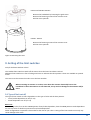
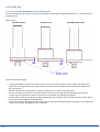
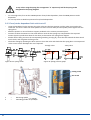
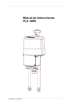
Operating Instructions
PSL Model 4
Version 07/12/2012
©2012 PS Automation GmbH
Subject to changes!
2
Contents
Type key ............................................................................................................................................................................ 3
1. Symbols and safety ....................................................................................................................................................... 4
2. Usage as per specification............................................................................................................................................. 5
3. Storage .......................................................................................................................................................................... 5
4. Operating conditions..................................................................................................................................................... 5
4.1 Installation position ................................................................................................................................................ 6
5. Function ........................................................................................................................................................................ 6
6. Manual operation ......................................................................................................................................................... 7
7. Valve mounting ............................................................................................................................................................. 8
7.1 PSL201-214.............................................................................................................................................................. 8
7.2 PSL320-325............................................................................................................................................................ 10
8. Removing the cover .................................................................................................................................................... 10
9. Setting of the limit switches........................................................................................................................................ 11
9.1 Type of limit cut-off............................................................................................................................................... 11
9.2 PSL 201-214 ........................................................................................................................................................... 12
9.2.1 Force/stroke-dependent limit switch cut-off................................................................................................. 12
9.2.2 Stroke-dependent limit switch cut-off ........................................................................................................... 13
9.3 PSL320-325............................................................................................................................................................ 13
9.3.1 Force/stroke-dependent limit switch cut-off................................................................................................. 13
9.3.2 Force/stroke-dependent limit switch cut-off................................................................................................. 14
9.3.3 Stroke-dependent limit switch cut-off ............................................................................................................... 15
10. Electric supply ........................................................................................................................................................... 15
10.1 Wiring diagram.................................................................................................................................................... 16
11. Commissioning .......................................................................................................................................................... 17
11.1 Refitting the cover............................................................................................................................................... 17
12. Service/ Maintenance ............................................................................................................................................... 17
12.1 Cleaning............................................................................................................................................................... 17
12.2 Spare Parts .......................................................................................................................................................... 17
13. Appendix ................................................................................................................................................................... 18
13.1 Accessoires .......................................................................................................................................................... 18
13.2 Actuator overview............................................................................................................................................... 19
Type key
Example
PSL204.1
/
230VAC
/ 50-60Hz / 53VA / 4,5kN /
1,00
Actuator type
Voltage supply
Frequency
Max. input power
Force
Stroking speed [mm/s]
3
1. Symbols and safety
General dangers of non-compliance with safety regulations
PSL actuators are built at state-of the art technology and are safe to operate. Despite of this, the actuators may be
hazardous if operated by personnel that has not been sufficiently trained or at least instructed, and if the actuators
are handled improperly, or not used as per specification.
This may
•
cause danger to life and limb of the user or a third party,
•
damage the actuator and other property belonging to the owner,
•
reduce safety and function of the actuator.
To prevent such problems, please ensure that these operating instructions and the chapter on "Safety" in particular
have been read and understood by all personnel involved in the installation, commissioning, operation, maintenance
and repair of the actuators.
Basic safety notes
• The actuators may only be operated by skilled and authorized operating personnel.
• Make sure to follow all security advices mentioned in this manual, any national rules for accident prevention, as
well as the owner´s instructions for work, operation and safety.
• The isolating procedures specified in these Operating Instructions must be followed for all work pertaining to the
installation, commissioning, operation, change of operating conditions and modes, maintenance, inspection,
repair and installation of accessories
• Before opening the actuator cover, ensure that mains supply is isolated and prevented from unintended reconnection.
• Areas that can be under voltage have to be isolated before working on them.
• Ensure that the actuators are always operated in faultless condition. Any damage or faults, and changes in the
operational characteristics that may affect safety, must be reported at once.
Danger signs
The following danger signs are used in this operating manual:
Caution! There is a general risk of damage related to health and/or properties.
Danger! Electrical voltages are present that may lead to death. Life threatening risks may occur
due to electrical voltages!
Danger! Electrical voltages are present that may lead to death. Life threatening risks may occur
due to electrical voltages!
4
Other notes
• The motor surface temperature may rise when maintaining, inspecting and repairing the actuator immediately
after the operation. There is a danger of burning the skin!
• Always consult the relevant operating instructions when mounting PS-S accessories or operating the actuator
with PS accessories.
• Connections for signal in- and output are double isolated from circuits that can be under dangerous voltage.
2. Usage as per specification
• PSL linear actuators are exclusively designed to be used as electric valve actuators. They are meant to be
mounted on valves in order to run their motors.
• Any other use is considered to be non-compliant and the manufacturer cannot be held liable for any damage
resulting from it.
• The actuators can only be used within the limits laid out in the data sheets, catalogues and other documents.
Otherwise, the manufacturer cannot be held liable for any resulting damage.
• Usage as per specification includes the observance of the operating, service and maintenance conditions laid
down by the manufacturer.
• Not to be regarded as usage as per specification are mounting and adjusting the actuator as well as servicing.
Special precautions have to be taken while doing this!
• The actuators may only be used, serviced and repaired by personnel that is familiar with them and informed
about potential hazards. The specific regulations for the prevention of accidents have to be observed.
• Damages caused by unauthorized modifications carried out on the actuators are excluded from the
manufacturer's liability.
• Supply voltage may only be switched on after the proper closure of the main cover or terminal box.
• Electrical wiring is done to a terminal block under the actuator cover.
3. Storage
For appropriate storage, the following instructions have to be met:
• Only store the actuators in ventilated, dry rooms.
• Store the actuators on shelves, wooden boards, etc., to protect them from floor moisture.
• Cover the actuators with plastic foil to protect them from dust and dirt.
• Protect the actuators against mechanical damage.
4. Operating conditions
• Standard actuators may be operated at ambient temperatures from -20°C to +60°C (S4 operation) or from -20°C
bis +80°C (S2 operation).
• Operating modes correspond to IEC 34-1, 8: S2 for short cycle and S4 for standard operation (for actuator specific
data see the table at the end of this document or the actuator specific data sheets).
• For protection against moisture and dust, the enclosure rating is IP65 or IP67 according to EN 60529.
• When installing the actuators, leave enough space to allow cover removal (Fig.1).
• The actuator can be installed vertically or horizontally or any position in between. The actuator must not be
installed with the cover pointing downwards (Fig.2).
5
PSL320-325
PSL214
PSL208-210
PSL201-204
Figure 1: Installation dimensions
4.1 Installation position
Outdoor usage:
When using the actuators in environments with high
temperature fluctuations or high humidity, we recommend
using a heating resistor as well as a higher enclosure rating
(optional accessories).
Figure 2: Installation positions
5. Function
The PSL actuators are designed as electric valve actuators. The valve is mounted onto the actuator via pedestals.
Depending on the type of valve used, mounting pedestals or a special valve mounting plate is required.
The motor torque is transmitted via a multi-stage spur gear onto a trapezoidal threaded spindle. The spindle
transmits the input torque into an axial thrust force via a stem nut. Thus the spindle stem nut which is self-locking
carries out a linear stroke transmitted to the valve spindle by a coupling piece. The actuating stroke is limited by two
adjustable limit switches in each direction that cut off the motor current.
In case of mains power loss, a manual override of the actuators is possible using the handwheel.
Electrical wiring is done to a terminal block under the actuator cover.
6
6. Manual operation
A handwheel is supplied in order to operate the actuator in case of power loss or during installation work such as
mounting onto a valve or setting the limit positions.
• The handwheel is permanently engaged and turns during motor operation of the device series PSL201-210 and
PSL305-314.
• The actuators PSL320 - 325 have a handwheel which has to be engaged for manual operation. The ball-headed
button on the cover has to be depressed to engage the handwheel.
Do not exceed the adjusted electrical stroke limits by handwheel.
The mechanical limits must be set accordingly.
If these instructions are not observed, it may result in malfunction or damage to the
actuator.
Do not operate the handwheel using excessive force. If these instructions are not
observed, it may result in malfunction or damage to the actuator.
*PSL21: Please remove the handwheel cover
Figure 3: Manual operation
7
7. Valve mounting
7.1 PSL201-214
Note: The pictures below show the mounting of a PSL204. The steps are identical for all types.
When mounting the actuator onto the valve, use the handwheel and do not drive the
actuator electrically.
If these instructions are not observed, it may result in personal injury or damage to the
actuator and/or valve.
Coupling
Pillar
Clamping screws
for spring pack
Coupling
nut
Valve stem
Locking nut
Bracket
Pillar
nut
①
Make sure that the
coupling nut can be
turned by hand
8
②
Drive coupling
completely upwards by
hand
③
Put Actuator onto Valve
④
⑤
Pillar end
Bracket
Bracket
Pillar nut
Appr. 5 mm
Leave 5 mm gap between
bracket and pillar nut
appr. 5 mm
Move the coupling down until it hits the valve stem.
Continue moving until there is a 5 mm gap
between the pillar end and the bracket.
⑥
Screw the coupling nut
onto the valve stem until
the pillar edges rest on
the bracket.
⑧
⑨
Lock the coupling nut
Tighten the clamping screws crosswise with 8 Nm
⑩
or
Drive the coupling up or down, until the
edges of the pillars rest on the bracket
WRONG
CORRECT
Tighten the pillar nuts
Before the fastening nuts are tightened, make sure that the pedestal ends are completely
inserted into the bores of the valve mounting plate. If necessary, correct the position of the
actuator by using the handwheel. If these instructions are not observed, it may result in
personal injury or damage to the actuator and/or valve.
9
7.2 PSL320-325
When mounting an actuator onto a valve, never drive the actuator electrically but use the
handwheel.
If these instructions are not observed, it may result in personal injury or damage to the
actuator and/or valve.
1
=
stroke scale
2
=
spindle nut with locking device
3
=
safety pin
4
=
coupling piece
5
=
valve mounting plate
6
=
fastening nut
7
=
valve body
8
=
valve spindle
9
=
swivel nut
10
=
disc springs
11
=
mounting pedestals
Figure 4: Mounting the actuator onto the valve
The valve must be suitably equipped to take the mounting pedestals. Please see the individual dimension sheets for
the actuator dimensions. Observe the following steps when mounting the actuator:
• Unscrew the swivel nut (item 9) from the spindle nut (item 2) and slide it over the valve spindle (item 8).
• See if the bore of the coupling piece fits the valve spindle. If necessary, rebore and/or recut the thread.
• Slide or screw the coupling piece (item 4) onto the valve spindle and bore or pin to the valve spindle (disc
springs, see chapter 8.2).
• Slide the valve spindle with the coupling piece and disc springs (item 10) into the spindle nut, screw on the
swivel nut and tighten it down using the cross slotted key supplied.
• Slide the actuating pedestals (item 11) into the bore holes of the valve mounting plate and tighten with the
fastening nuts.
Before the fastening nuts are tightened, make sure that the
pedestal ends are completely inserted into the bores of the valve
mounting plate. If necessary, correct the position of the actuator
using the handwheel. If these instructions are not observed, it may
result in damage to the actuator and/or valve.
8. Removing the cover
Please observe the label on the cover of the actuator.
PSL201-PSL210
Remove the handwheel by loosening it.
Pull the cover upwards.
10
PSL214 und PSL201-210 IP67
Remove the handwheel by loosening the grub screw.
Remove the fastening screws of the actuator cover.
Pull the cover upwards.
PSL320 - PSL325
Remove the fastening screws of the actuator cover
Pull the cover upwards.
Figure 5: Removing the cover
9. Setting of the limit switches
Only for deliveries without valves!
The standard limit switches switch-off the motor when the limits have been reached.
Additional limit switches are free of voltage and serve to indicate the valve position. These are available as optional
extras.
The cover must be removed in order to set the limit switches.
When mounting an actuator on a valve, never drive the actuator electrically but use the
handwheel. If these instructions are not observed, it may result in damage to the actuator and/or
valve.
9.1 Type of limit cut-off
The type of limit switch cut-off is dependent on the type of valve and the limit position:
• Force/stroke-dependent cut-off (cf. 9.2)
• Stroke-dependent cut-off (cf. 9.3)
Basic rule:
For a through-valve, first set the CLOSED position force/stroke-dependent, then the OPEN position stroke-dependent
For a 3-way valve set both limit positions force/stroke-dependent.
Other arrangements are possible. Please observe the data of your valve. Cutting off the limit switch incorrectly may
cause damage to the valve.
11
9.2 PSL 201-214
9.2.1 Force/stroke-dependent limit switch cut-off
For force-dependant limit switch cut-off, the limit switches can be set by using the compression „s“ of the spring disc
coupling (Fig. 6).
Edge notch in
TOP limit position
Position of rest
BOTTOM limit position
Figure 6: Standard coupling
•
•
•
•
•
12
Using the handwheel on the actuator, drive the valve into the limit position until the valve cone touches the
valve seat. This happens when the valve spindle nut starts to move axially and the spindle pushes against the
disc spring force.
Mark the position on one of the drive support pedestals at the rotation protection piece.
Continue to drive the actuator in the same direction until the disc springs are compressed to the required
amount (see the specific data sheet for the drive) as denoted on the spring/force diagram.
Slacken-off the fixing screw on the corresponding switching cam (Fig. 8), move the cam towards the limit switch
until it clicks, and re-tighten the fixing screw.
Check the setting by repeating the drive action to close the valve and check that the spring discs are compressed
to the correct stroke. Re-adjust the cam if required.
②
Locking screw
Gear screw
1
2
=
=
Retracting spindle nut (OPEN)
Extending spindle nut (CLOSE)
①
Figure 7: Adjusting switching cams
9.2.2 Stroke-dependent limit switch cut-off
The spring discs are not compressed for the stroke dependent limit switch cut-off.
- Using the handwheel of the actuator, drive the valve until the required end position is reached.
- Slacken-off the fixing screw on the corresponding switching cam (Fig. 7), move the cam towards the limit
switch until it activates, and re-tighten the fixing screw.
- Check the settings by driving into the end position again and measure the valve stroke.
- Überprüfen der Einstellung durch erneutes Anfahren der Endposition und messen des Ventilhubes. Re-adjust
the cam if required.
9.3 PSL320-325
9.3.1 Force/stroke-dependent limit switch cut-off
A
B
C
Figure 8: Standard disc spring coupling
The different methods of arranging the discs are dependent on the type of valve. Three different methods are
possible:
A: Arrangement for a through-valve with "Valve Spindle retracting" as direction of closing.
B: Arrangement for a 3-way valve.
C: Arrangement for a through valve with "Valve Spindle extending" as direction of closing.
13
3-way valves using the spring disc arrangement "C" require only half of the spring stroke
designated in the spring diagram!
Basic rule:
• For a through-valve, first set the CLOSED position force/stroke-dependent, then the OPEN position strokedependent
• For a 3-way valve set both limit positions force/stroke-dependent.
9.3.2 Force/stroke-dependent limit switch cut-off
•
•
•
•
•
Using the handwheel on the actuator, drive the valve into the limit position until the valve cone touches the
valve seat. This occurs when the valve spindle nut starts to move axially and the spindle pushes against the disc
spring force.
Mark the position on one of the drive support pedestals at the rotation protection piece.
Continue to drive the actuator in the same direction until the disc springs are compressed to the required
amount (see the specific data sheet for the drive) as denoted on the spring/force diagram.
Slacken-off the fixing screw on the corresponding switching cam (Fig. 8), move the cam towards the limit switch
until it clicks, and re-tighten the fixing screw.
Check the setting by repeating the drive action to close the valve and check that the spring discs are compressed
to the correct stroke. Re-adjust the cam if required.
Through-valve
3-way-valve
Figure 9: Disc spring stroke
Figure 10: Spring pressure graph
②
Locking screw
Gear screw
1
2
14
=
=
Retracting spindle nut (OPEN)
Extending spindle nut (CLOSE)O
①
9.3.3 Stroke-dependent limit switch cut-off
The spring discs are not compressed for the stroke dependent limit switch cut-off.
- Using the handwheel of the actuator, drive the valve until the required end position is reached.
- Slacken-off the fixing screw on the corresponding switching cam (Fig. 7), move the cam towards the limit
switch until it activates, and re-tighten the fixing screw.
- Check the settings by driving into the end position again and measure the valve stroke.
- Überprüfen der Einstellung durch erneutes Anfahren der Endposition und messen des Ventilhubes. Re-adjust
the cam if required.
10. Electric supply
Before connecting to the mains, ensure that the mains supply is isolated and secured
against an accidental switching-on.
Remove the cover of the actuator in order to connect the electric supply (cf. 8, Removing the cover).
The mains connecting cables must be suitably dimensioned to accept the max. current requirement of the actuator.
The yellow-green coloured cables may only be used for connecting to earth.
When you insert the cable through the drive cable connector, ensure that the max. bending radius for the cable is
observed.
The PSL electric actuators do not have an internal electrical power switch. A switch or power mains switch must be
provided in the building installation. It should be positioned closely to the device and be easily accessible for the user
and shall be labelled as the mains isolator switch for the actuator.
The building installation must also provide power surge trips or fuses corresponding to standard IEC 364-4-41 with
protection class 1 resp. protection class 3 (24VAC/24VDC) for the actuator connections.
15
10.1 Wiring diagram
Figure 10 indicates the electrical connections for standard actuators. The wiring diagram inside the actuator cover is
binding for the specific actuator connection. See the separate wiring diagram in the corresponding service
instructions for any optional extras.
X1 =
X2 =
X3 =
X4 =
X5/1 =
X5/2 =
X5/4 =
X6 =
X7 =
X9 =
X0 =
X11 =
PE =
Internal wiring
Internal wiring
Internal wiring
Potentiometer 1 tap (optional
accessories)
Neutral
Motor phase to open
Motor phase to close
Additional position switch (optional
accessories)
not used
Potentiometer 2 tap (optional
accessories)
Potentiometer 1 connection
(optional accessories)
Potentiometer 2 connection
(optionales Zubehör)
Earth connection on housing
Figure 10: Wiring terminals
0
1
2
4
6
X5
7
20
19
18
17
12
11
12V/24V DC
t
16
15
14
X5
13
3-Phasen Drehstrom
3-Phase a.c.
PE
4
2
1
PE
1-Phasen Wechselstrom
1-Phase a.c.
X5
Weg /
Position
t
Weg /
Position
Zu /
Close
Weg /
Position
L3
M2
=
M1
N
F
L1
L1
L2
L2
t
Auf /
Open
N
Index C
Figure 11: Wiring diagram
PE Earth connection on housing plate has to be connected!
Two adjustable limit switches are installed to limit the stroke of the actuator, and cut-off the motor current in the
relative direction. (see 9.1 ff)
16
Most motors have a thermal switch, depending on the actuator type, to cut off the current in both directions when a
maximum temperature is reached.
11. Commissioning
•
•
•
•
Put the cover on, and re-install the handwheel (see “11.1 Refitting the cover”).
Drive the valve to the centre of the stroke using the handwheel
Switch on the mains.
Switch the setting signal briefly between OPEN and CLOSE and check that the drive operates in the correct
direction. If necessary, reverse the setting signal for OPEN/CLOSE.
• Drive the actuator, in both directions, using the setting signal until the limit switch cuts-off. Check that the limit
switch position is correct. If necessary re-adjust the limit switch.
11.1 Refitting the cover
PSL201-PSL210
Please observe the label on the cover of the actuator.
PSL320-PSL325
• Check that the sealing ring on the periphery of the housing sits correctly in the groove.
• Move the cover over the gear housing and ensure that the 3 fixing screws are
positioned over the corresponding threaded holes of the gear housing.
• Tighten down the fixing screws with a corresponding screwdriver.
Figure 12: Refitting the cover
12. Service/ Maintenance
The actuators are maintenance-free if used under the operating conditions as designated in the data sheet. The
gearboxes are lubricated for life and do not require further lubrication.
12.1 Cleaning
The actuators should be cleaned dry.
12.2 Spare Parts
Defective actuators should be returned to our plant in Bad Dürkheim, Germany, or to our representatives, to be
checked for damages and their possible causes.
If you prefer repairs in-house, we can provide you our price list for spare parts.
17
13. Appendix
13.1 Accessoires
Accessories/
Options
Various options are available in order to adapt the actuators to the various service conditions. A list of
accessories for each actuator type is shown on the actuator data sheet.
Add. position
switches
Add. Position
switches
Gold
Positioner card
Position transmitter
Heating resistor
IP Enclosure
2WE
2WE
Gold
PSAP
PSPT
HR
IP
230 VAC
1~
115 VAC
1~
24 VAC 1~
400 V 3~
24 VDC
•
•
•
•
•
•
•
•
•
•
•
•
•
•
•
•
•
•
•
•
•
•
•
•
•= available, for part number see data sheets
18
• IP67 with metal cover
13.2 Actuator overview
PSL 201-204
1 kN bis 4,5 kN
Force
0,25 bis 1,4 mm/s
Stroking speed
max. 50 mm
Stroke
PSL 208-210
8 kN bis 10 kN
Force
0,35 bis 1,0 mm/s
Stroking speed
max. 50 mm
Stroke
PSL 214
14 kN
Force
0,45 mm/s
Stroking speed
max. 65 mm
Stroke
PSL 320-325
20 kN bis 25 kN
Force
1,0 mm/s
Stroking speed
max. 100 mm
Stroke
19
Great Britain
IMTEX Controls Ltd.
Unit 5A, Valley Industries,
Hadlow Road
GB-Tonbridge, Kent TN11 0AH
Tel.: <+44> (0) 17 32-85 03 60
Fax: <+44> (0) 17 32-85 21 33
eMail: [email protected]
www.imtex-controls.com
Hong Kong
PS-MAXONIC Hong Kong Ltd.
Room 803-4, Yale Industrial Centre
61-63 Au Pui Wan Street
Fotan, Shatin, Hong Kong
Tel.: <+852> 26 87-50 00
Fax: <+852> 81 01-37 43
eMail: [email protected]
www.maxonicauto.com
Italy
PS Automazione S.r.l.
Via Pennella, 94
I-38057 Pergine Valsugana (TN)
Tel.: <+39> 04 61-53 43 67
Fax: <+39> 04 61-50 48 62
eMail: [email protected]
China
SHENZHEN MAXONIC AUTOMATION
Control Co Ltd.
7th Floor, Block 7, Tian An Industrial Estate
Nanyou, Shenzhen, Guangdong
P. R. CHINA
Tel.: <+86> 7 55 26 52 18 78
Fax: <+86> 7 55 26 05 28 00
eMail: [email protected]
www.maxonicauto.com
Switzerland
Avintos Flow Control AG
Weidenweg 17
CH-4310 Rheinfelden
Tel.: <+41>61-83 61-5 30
Fax: <+41>61-83 61-5 99
eMail: [email protected]
www.avintos.com
Spain
Sertemo, S.L.
Pol. Ind. Alba - Avda. Generalitat 15
Apartado de Correos, 142
E-43480 Vila-Seca (Tarragona)
Tel. : <+34> 9 77 39 11 09
Fax : <+34> 9 77 39 44 80
eMail : [email protected]
www.sertemo.com
PS Automation GmbH
Gesellschaft für Antriebstechnik
Philipp-Krämer-Ring 13
D-67098 Bad Dürkheim
Tel.: +49 (0) 63 22 - 60 03 – 0
Fax: +49 (0) 63 22 - 60 03 – 20
eMail: [email protected]
www.ps-automation.com
20
India
PS Automation India Pvt Ltd.
Srv. No. 25/1, Narhe Industrial Area,
A.P. Narhegaon, Tal. Haveli, Dist.
IND-411041 Pune
Tel. : <+ 91> 20 25 47 39 66
Fax : <+ 91> 20 25 47 39 66
eMail : [email protected]
www.ps-automation.in