1
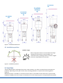
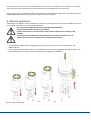
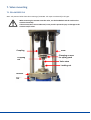
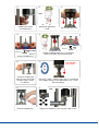
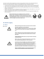
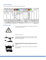
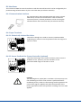
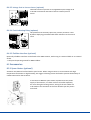
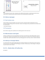
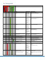
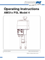
Operating Instructions
AMS1x PSL Model 4
Version 07/12/2012
©2012 PS Automation GmbH
Subject to changes without notice!
1
2
Contents
1. Symbols and safety .............................................................................................................................. 4
2. Usage as per specification ................................................................................................................... 5
3. Storage ................................................................................................................................................. 5
4. Operating conditions ........................................................................................................................... 5
4.1 Installation position ....................................................................................................................... 6
5. Function ............................................................................................................................................... 6
6. Manual operation ................................................................................................................................ 7
7. Valve mounting .................................................................................................................................... 8
7.1 PSL-AMS202-214............................................................................................................................ 8
7.2 PSL-AMS320-325.......................................................................................................................... 10
8. Electric supply .................................................................................................................................... 11
8.1 Safety ........................................................................................................................................... 11
8.2 Wiring diagram ............................................................................................................................ 12
8.3 Mains supply ................................................................................................................................ 12
8.4 Interfaces ..................................................................................................................................... 13
8.4.1 Communication Interface ..................................................................................................... 13
8.4.2 Input Terminals ..................................................................................................................... 13
8.4.2.1 Galvanically isolated Set-Value .......................................................................................... 13
8.4.2.2 Sensor Feedback for Process Controller (optional) ........................................................... 13
8.4.2.3 Galvanically Isolated Binary Input ..................................................................................... 14
8.4.2.4 Fail-safe port for Binary Input (optional) ........................................................................... 14
8.4.3 Output Terminals .................................................................................................................. 14
8.4.3.1 Active Position Feedback ................................................................................................... 14
8.4.3.2 Additional Position Switches (optional)............................................................................. 14
8.4.3.3 Voltage feed to Process Sensor (optional) ........................................................................ 15
8.4.3.4 Fault Indicating Relay (optional) ................................................................................... 15
8.4.3.5 Fieldbus Interface (optional) ............................................................................................. 15
8.5 Accessories................................................................................................................................... 15
8.5.1 Space Heater (optional) ............................................................................................................ 15
8.5.3 Adjusting Additional Position Switches (optional)................................................................ 16
9. Status display/ Operating element .................................................................................................... 16
10. Operation ......................................................................................................................................... 17
10.1 Cut-off in End Positions ............................................................................................................. 17
10.1.1 Cut-Off by Force / Torque ................................................................................................... 17
10.1.2 Cut-Off by Position automatically ....................................................................................... 17
10.1.3 Cut-Off by Position.............................................................................................................. 17
11. Commissioning................................................................................................................................. 17
11.1 Automatic commissioning ......................................................................................................... 18
11.2 Manual commisioning ............................................................................................................... 18
12. Status messages ............................................................................................................................... 19
12.1 Fault indicator relay ................................................................................................................... 19
12.2 Tracing faults.............................................................................................................................. 19
13. Maintenance and repair .................................................................................................................. 19
14. Safety on transportation.................................................................................................................. 19
15. CE – Declaration of Conformity ....................................................................................................... 19
16. Tracing faults.................................................................................................................................... 20
3
1. Symbols and safety
General dangers of non-compliance with safety regulations
PSL actuators are built at state-of the art technology and are safe to operate. Despite of this, the actuators
may be hazardous if operated by personnel that has not been sufficiently trained or at least instructed, and if
the actuators are handled improperly, or not used as per specification.
This may
•
cause danger to life and limb of the user or a third party,
•
damage the actuator and other property belonging to the owner,
•
reduce safety and function of the actuator.
To prevent such problems, please ensure that these operating instructions and the chapter on "Safety" in
particular have been read and understood by all personnel involved in the installation, commissioning,
operation, maintenance and repair of the actuators.
Basic safety notes
• The actuators may only be operated by skilled and authorized operating personnel.
• Make sure to follow all security advices mentioned in this manual, any national rules for accident
prevention, as well as the owner´s instructions for work, operation and safety.
• The isolating procedures specified in these Operating Instructions must be followed for all work pertaining
to the installation, commissioning, operation, change of operating conditions and modes, maintenance,
inspection, repair and installation of accessories
• Before opening the actuator cover, ensure that mains supply is isolated and prevented from unintended reconnection.
• Areas that can be under voltage have to be isolated before working on them.
• Ensure that the actuators are always operated in faultless condition. Any damage or faults, and changes in
the operational characteristics that may affect safety, must be reported at once.
Danger signs
The following danger signs are used in this operating manual:
Caution! There is a general risk of damage related to health and/or properties.
Danger! Electrical voltages are present that may lead to death. Life threatening risks may occur
due to electrical voltages!
Danger! This sign warns of hazards posing a risk to health. Ignoring these instructions can lead to
injuries.
4
Other notes
• The motor surface temperature may rise when maintaining, inspecting and repairing the actuator
immediately after the operation. There is a danger of burning the skin!
• Always consult the relevant operating instructions when mounting PS-S accessories or operating the
actuator with PS accessories.
• Connections for signal in- and output are double isolated from circuits that can be under dangerous
voltage.
2. Usage as per specification
• PSL linear actuators are exclusively designed to be used as electric valve actuators. They are meant to be
mounted on valves in order to run their motors.
• Any other use is considered to be non-compliant and the manufacturer cannot be held liable for any
damage resulting from it.
• The actuators can only be used within the limits laid out in the data sheets, catalogues and other
documents. Otherwise, the manufacturer cannot be held liable for any resulting damage.
• Usage as per specification includes the observance of the operating, service and maintenance conditions
laid down by the manufacturer.
• Not to be regarded as usage as per specification are mounting and adjusting the actuator as well as
servicing. Special precautions have to be taken while doing this!
• The actuators may only be used, serviced and repaired by personnel that is familiar with them and
informed about potential hazards. The specific regulations for the prevention of accidents have to be
observed.
• Damages caused by unauthorized modifications carried out on the actuators are excluded from the
manufacturer's liability.
• Supply voltage may only be switched on after the proper closure of the main cover or terminal box.
• Electrical wiring is done to a terminal block under the actuator cover.
3. Storage
For appropriate storage, the following instructions have to be met:
• Only store the actuators in ventilated, dry rooms.
• Store the actuators on shelves, wooden boards, etc., to protect them from floor moisture.
• Cover the actuators with plastic foil to protect them from dust and dirt.
• Protect the actuators against mechanical damage.
4. Operating conditions
• Standard actuators may be operated at ambient temperatures from -20°C to +60°C.
• Operating modes correspond to DIN EN 60034-1: S2 for short cycle and S4 for standard operation (for
actuator specific data see the actuator specific data sheets).
• For protection against moisture and dust, the enclosure rating is IP65 or IP67 according to EN 60529.
• When installing the actuators, leave enough space to allow cover removal (Fig.1).
• The actuator can be installed vertically or horizontally or any position in between. The actuator must not be
installed with the cover pointing downwards (Fig.2).
5
PSL-AMS320325
PSL-AMS208214 (Stroke
50)
PSL-AMS208214 (Stroke
65)
PSL-AMS202204
Figure 1: Installation dimensions
4.1 Installation position
Outdoor usage:
When using the actuators in environments with high
temperature fluctuations or high humidity, we
recommend using a heating resistor as well as a higher
enclosure rating (optional accessories).
Figure 2: Installation positions
5. Function
The PSL-AMS actuators are designed as electric valve actuators. The valve is mounted onto the actuator via
pedestals. Depending on the type of valve used, mounting pedestals or a special valve mounting plate is
required.
Mechanical power is created by a 24 volts DC-motor which is controlled from the electronics via pulse width
modulation (PWM). The motor torque is transmitted via a multi-step spur gear to a trapezoidal thread spindle.
6
The spindle itself converts the induced torque into an axial force via a spindle nut. The spindle nut‘s resulting
linear vertical motion is self-locking and is transmitted via a coupling piece to the valve stem.
During power failure and adjustment work the actuators can be emergency-operated via the hand wheel (see
chapter 5/Manual Operation), except when using the fail-safe unit PSCP.
6. Manual operation
A handwheel is supplied in order to operate the actuator in case of power loss or during installation work such
as mounting onto a valve or setting the limit positions.
Do not exceed the adjusted electrical stroke limits by handwheel.
The mechanical limits must be set accordingly.
If these instructions are not observed, it may result in malfunction or damage to the
actuator.
Do not operate the handwheel using excessive force. If these instructions are not
observed, it may result in malfunction or damage to the actuator.
• The handwheel is permanently engaged and turns during motor operation of the device series PSLAMS1x202-214.
• The actuators PSL-AMS1x320 - 325 have a handwheel which has to be engaged for manual operation. The
ball-headed button on the cover has to be depressed to engage the handwheel.
Figure 3: Manual operation
*PSL-AMS208-214 Stroke 65m: Please remove the handwheel cover
7
7. Valve mounting
7.1 PSL-AMS202-214
Note: The pictures below show the mounting of a PSL204. The steps are identical for all types.
When mounting the actuator onto the valve, use the handwheel and do not drive the
actuator electrically.
If these instructions are not observed, it may result in personal injury or damage to the
actuator and/or valve.
Coupling
Coupling
nut
Pillar
Clamping screws
for spring pack
Valve stem
Locking nut
Bracket
Pillar
nut
8
①
③
②
8 Nm
Make sure that the
coupling nut can be
turned by hand
④
Drive coupling
completely upwards by
hand
Put actuator onto valve.
⑤
Pillar end
Bracket
Bracket
Pillar nut
Appr. 5 mm
Leave 5 mm gap between
bracket and pillar nut
⑥
Appro. 5
mm
Move the coupling down until it hits the valve stem.
Continue moving until there is a 5 mm gap
between the pillar end and the bracket.
⑦
12 mm (M8, M12) /
16 mm (> M14)
⑤
+
⑥
Screw the coupling nut
onto the valve stem until
the pillar edges rest on
the bracket.
⑧
Lock the coupling nut.
Repeat ⑤ and ⑥ until the valve stem is screwed into
the coupling nut by 12 mm (M8 to M12) resp. 16 mm
(M14 and larger).
⑨
8 Nm
Tighten the clamping screws crosswise with 8 Nm.
9
⑩
or
Drive the coupling up or down, until the
edges of the pillars rest on the bracket.
WRONG
CORRECT
⑪
Tighten the pillar nuts.
Before the fastening nuts are tightened, make sure that the pedestal
ends are completely inserted into the bores of the valve mounting
plate. If necessary, correct the position of the actuator by using the
handwheel. If these instructions are not observed, it may result in
personal injury or damage to the actuator and/or valve.
7.2 PSL-AMS320-325
When mounting an actuator onto a valve, never drive the actuator
electrically but use the handwheel.
If these instructions are not observed, it may result in personal injury
or damage to the actuator and/or valve.
1
2
3
4
5
6
7
8
9
10
11
Figure 4: Mounting the actuator onto the valve
10
=
=
=
=
=
=
=
=
=
=
=
stroke scale
spindle nut with locking device
safety pin
coupling piece
valve mounting plate
fastening nut
valve body
valve spindle
swivel nut
disc springs
mounting pedestals
The valve must be suitably equipped to take the mounting pedestals. Please see the individual dimension
sheets for the actuator dimensions. Observe the following steps when mounting the actuator:
• Unscrew the swivel nut (item 9) from the spindle nut (item 2) and slide it over the valve spindle (item 8).
• See if the bore of the coupling piece fits the valve spindle. If necessary, rebore and/or recut the thread.
• Slide or screw the coupling piece (item 4) onto the valve spindle and bore or pin to the valve spindle (disc
springs, see chapter 8.2).
• Slide the valve spindle with the coupling piece and disc springs (item 10) into the spindle nut, screw on the
swivel nut and tighten it down using the cross slotted key supplied.
• Slide the actuating pedestals (item 11) into the bore holes of the valve mounting plate and tighten with
the fastening nuts.
Before the fastening nuts are tightened, make sure that the
pedestal ends are completely inserted into the bores of the valve
mounting plate. If necessary, correct the position of the actuator
using the handwheel. If these instructions are not observed, it may
result in damage to the actuator and/or valve.
8. Electric supply
8.1 Safety
Safety note
When performing electric work on this unit, the local accident
prevention regulations must be followed.
Observe EN 60204-1 (VDE 0113 part 1) to ensure human safety,
integrity of the assets as well as the proper functioning of the
unit.
Electric supply lines must be dimensioned for the peak current
of the unit and comply with IEC 227 and IEC 245. See relevant
data sheet.
Yellow-and-green coded cords may only be used for connection
to protective earth.
When leading wires through the cable glands on the actuator,
their minimum bending radius has to be considered.
The electric actuators PSL-AMS are not fitted with an internal
electric isolator, hence a switching device or circuit breaker
must be integrated in the facility. It should be installed close to
the actuator and should be easy to access for the user. It is
important to mark the circuit breaker as this actuator‘s isolator.
Electric installations and over-current protection devices must
conform to the standard IEC 364-4-41, protective class I.
11
8.2 Wiring diagram
Electric terminals are provided in a terminal box at the actuator.
8.3 Mains supply
Isolate the power supply. Safeguard the line against unauthorized
and unintended restarting.
Open the terminal box.
The terminal box provides terminals to accommodate rigid and
flexible cables of wire widths of 0.14 mm² to 2.5 mm² as well as a
PE screw on the housing.
Caution: Please observe the supply voltage and the maximum
power consumption of the actuator as indicated on the actuator‘s
tag plate!
Connect supply and control lines to terminals (as indicated in the
wiring diagram).
12
8.4 Interfaces
The actuator PS-AMS has several interfaces inside the terminal box which can be configured by the
parameterising software PSCS or by the control box PSC (see relevant manuals).
8.4.1 Communication Interface
For communication and parameterisation with a PC or a handheld device, connect the communication cable to the RJ45connector (item 4). Actuator parameters can be set using the
software PSCS or the control box PSC (see relevant manuals).
8.4.2 Input Terminals
8.4.2.1 Galvanically isolated Set-Value
1 2 3
Terminals 1 through 3 are used to receive a parameterisable
modulating set-value for control operation within the range of 020 mA or 0-10V.
8.4.2.2 Sensor Feedback for Process Controller (optional)
15 16 17
Terminals 15 through 17 are used to receive a process sensor‘s
feedback to the - optional - process controller, in the
parameterisable range of 0-20 mA or 0-10 V.
Caution!
The following binary inputs (8.4.2.3 und 8.4.2.4) have priority over
the modulating set-value. If the actuator is parameterised for
modulating service, these set-value settings are disregarded in the
case a binary signal is applied. Only after disconnection of the
binary signal the actuator will reposition according to the set-value
applied.
13
8.4.2.3 Galvanically Isolated Binary Input
9 10 11
Terminals 9 through 11 are for binary open/close signals. Standard
voltage level is 24 V, option is for 115/230 V; see wiring plan. The
actuator is then driven in 3-point service.
8.4.2.4 Fail-safe port for Binary Input (optional)
The fail-safe port (terminals 12 and 13) allows driving the actuator
to a parameterized safety position by applying a voltage of 24 V.
12 13
8.4.3 Output Terminals
8.4.3.1 Active Position Feedback
Terminals 4 through 6 are giving active position feedback,
parameterisable within the range of 0-20mA or 0-10V.
4 5 6
8.4.3.2 Additional Position Switches (optional)
18 19 20 21
14
The activation points of the optionally available position switches
are freely adjustable via cams. Terminals 18/19 and 20/21 provide
potential-free opening or closing contacts. The standard switches
are rated to 230VAC/5A. Special switches with gold plated contacts
are available for low power (up to 100 mA and 30V).
8.4.3.3 Voltage feed to Process Sensor (optional)
14
Terminals 14 and 17 provide an unregulated output voltage of 24
to 30 VAC at maximum 100 mA to feed an external process
sensor.
17
8.4.3.4 Fault Indicating Relay (optional)
7
8
This potential-free normally-open relay contact (terminals 7 and
8) allows displaying parameterisable fault indication to the control
room.
8.4.3.5 Fieldbus Interface (optional)
Optionally a fieldbus interface can be fitted to the AMS-actuator, with wiring to a terminal block or an external
socket.
-> See special operating manual for AMS-Fieldbus.
8.5 Accessories
8.5.1 Space Heater (optional)
Actuators PSL-AMS can be fitted with a space heater. When using actuators in environments with high
temperature fluctuations or high humidity, we suggest a heating resistor be fitted to prevent the build-up of
condensation within the enclosure.
In actuators PS-AMS the space heater is powered via the power
supply of the actuator, so it does not have to be fed separately.
For retro-fitting the heating resistor, wiring of the two cables has
to be made to the terminals on the main board as per the picture
on the left.
15
Mounting of the space heater has to be made to the indicated
place on the base plate by using the screws provided. Route the
cables in a way to prevent them from being squashed by the main
cover, and from being touched by moving parts inside the
actuator.
8.5.3 Adjusting Additional Position Switches (optional)
In PSL-AMS two switches for position feedback are available as factory-mounted option.
They are either normally-closed or normally-open contacts, potential-free. They are available with silver
contacts (for currents between 10 mA and 5 A at maximum 230 V) or with gold-plated contacts (for currents
between 0,1 mA and 30 mA at maximum 30 V). Connection goes to terminals 18/19 and 20/21.
The cams for closing the switches are located on the switch plate,
and are adjustable with a small screwdriver. Cam 1 is for
retracting the spindle nut, while cam 2 is for extending the spindle
nut out of the actuator.
The potentiometer must not be adjusted. Non-observance may
cause damage to the actuator!
9. Status display/ Operating element
A red and a green LED on top of each other inside the terminal box
indicate the status of the actuator.
Another single red LED (optional) signals the status of the optional
fieldbus interface. -> See special operating manual for AMSFieldbus.
The commissioning button for starting the automatic
commissioning run (to adjust the actuator to the valve) is located
inside the terminal box, below the communication port.
16
10. Operation
All internal parameters, like required motor torque, actual position, functional status, etc., are being
permanently monitored during operation of the actuator PS-AMS. This ensures that the actuator positions
with optimum accuracy, and closes the valve always tight. Deviations can be read out via communication
software PSCS or via local control PSC.2 (see respective instruction manuals), or can be displayed to the control
room using the optional fault indication relay. This provides maximum safety of the process.
10.1 Cut-off in End Positions
Cut-offs of the PS-AMS actuators can be adjusted to meet the valve function in an optimum way by using the
communication software PSCS (using a special interface cable, or optionally Bluetooth connection). This will
result in different behavior of the actuator. In case a position is surpassed or not reached, this can be read out
via the optional Fault Indication Relay or via the communication software PSCS.
10.1.1 Cut-Off by Force / Torque
Der Antrieb bringt bei jedem Anfahren der Endlage das eingestellte maximale Drehmoment auf. Wenn sich der
Anschlag in der Armatur verschiebt, zum Beispiel durch Verschleiß einer Sitzdichtung, dann führt der Antrieb
im Rahmen seines möglichen Verfahrwegs den Schließpunkt nach.
10.1.2 Cut-Off by Position automatically
In normal operation, the actuator will stop at the position which was found at a mechanical stop in the valve or
the actuator during Automatic Commissioning. If the closing point inside the valve dislocates, the actuator will
NOT follow this dislocation but it will always stop at the point initially found.
10.1.3 Cut-Off by Position
In normal operation, the actuator will stop at the point which was defined by Manual Commissioning. This
position is not depending on any mechanical stop inside valve or actuator.
11. Commissioning
The actuator is shipped in the „not commissioned“condition with the green LED flashing slowly. There will be
no response to any input (set value or open/close signal). To make the actuator operational, it has to be
commissioned to a valve.
Depending on the type of cut-offs programmed (see 10.1) there are two ways to do commissioning:
- Automatic commissioning is done if at least one of the cut-offs is set to be “by force/torque” or “by position
automatically”.
- Manual commissioning has to be made in case both cut-offs are “by position”, either via software PSCS or via
control box PSC.2.
17
Caution!
Electrical operation of the actuator is allowed only after mounting
to a valve!
11.1 Automatic commissioning
(Only available if at least one of the cut-offs is set to be “by force/torque” or “by position automatically”.
①
②
Press the commissioning button for 3 sec
Commissioning in progress (Grenn LED is
flashing, actuator drives in both positions)
③
Green LED lights – Actuator successfully
commissioned and ready tob e used
11.2 Manual commisioning
①
Connect your PSCS-USB
cable with your PC and start
the software PSCS
18
②
③
Select actuator type and
interface in the software
Select Operate ->
Commissioning and confirm
the dialog wiht OK
④
Adjust the 0-Point and
check it with „send“;
Save with OK
⑤
Green LED lights – Actuator
successfully commissioned and
ready to be used
Note
If the parameterised valve stroke, starting from the adjusted closed position, exceeds the possible actuator
stroke, then the operating stroke will be reduced to the resulting maximum possible value.
12. Status messages
12.1 Fault indicator relay
Fault messages can be transmitted to the control room with a maximum load of 24 VDC/100 mA via an
optionally available closing contact at terminals 7 and 8. The messages can be parameterised via software PSCS
or control box PSC.
-> See relevant manuals
12.2 Tracing faults
See the table on page 20 for explanation of the blinking codes of the status-LEDs.
13. Maintenance and repair
Under the conditions of use as per specification as lined out in the data sheet, the PS-AMS actuators are free
of maintenance. All gears are lubricated for their service life and do not require to be re-lubricated. Clean the
actuators with a dry soft cloth and do not use any cleaning agent. Do not use any coarse or abrasive materials.
14. Safety on transportation
For transportation and storage all cable glands and connection flanges have to be closed to prevent ingress of
moisture and dirt. A suitable method of packaging is required for transporting to avoid damage of coating and
any external parts of the actuator.
15. CE – Declaration of Conformity
See page 23.
19
16. Tracing faults
Red LED
Green LED
off
Flashing slowly
Flashing quickly
Glowing
permanently
off
Flashing slowly
Flashing quickly
Glowing
permanently
x
x
Status
Probable reasons
Possible remedy
Actuator does not respond, both LEDs
are off
1) No supply
voltage applied
2) The applied
voltage does not
match the
actuator voltage
on the tag plate
1) Actuator not
correctly
commissioned
2) Too small
stroke
programmed (in
mode “one
positiondependent cutoff”)
1) Actuator not
correctly
commissioned
2) Actuator
closing force/
torque too low
1) Fixed digital
set-value is
activated
2) Actuator is
configured to
work with process
controller
A non-linear valve
curve has been
parameterised
Probable reasons
1) Check mains supply
2) Apply correct supply voltage
x
x
Actuator does not drive the full stroke
x
x
Actuator does not close the valve
properly
x
x
Actuator is in normal operating
condition, but does not respond to setvalue changes
x
x
Actuator position does not correspond
to set-value input
x
x
Operating conditions
x
x
20
1) Repeat commissioning
2) Check actuator selection
1) Check set-value parameters -> see
instrucions AMS-PSCS
2) Connect process sensor
Verify parameterised characteristic -> see
instructions AMS-PSCS
Possible remedy
Normal operating condition
X
x
x
1) Repeat commissioning
2) Check valve stroke parameters -> see
instructions AMS-PSCS
Actuator in commissioning mode
x
x
X
Actuator not commissioned
Faults within the actuator’s
environment
Probable reasons
Too high torque has been encountered
within the valve stroke
1) Actuator not
correctly
commissioned to
the valve
2) Mechanical
block within the
stroke path
3) Improper
selection of the
actuator
1) Process
feedback wrongly
or not at all
connected
2) Process
feedback outside
od adjusted range
1) No proper process feedback (only in
combination with PSIC)
2+3) Maximum control range exceeds
(only in combination with PSIC)
Commissioning mode will be left
automatically after completion
Depending on the type of cut-offs, the
actuator has to be commissioned either
automatically or manually
Possible remedy
1) Repeat commissioning
2) Check valve and actuator for unobstructed
running
3) Check actuator selection
1) Apply the correct process feedback signal
and check polarity
2) Ensure the correct process feedback range
3) Check the process sensor and its supply
voltage
Red LED
Green LED
x
x
x
off
Flashing slowly
Flashing quickly
Glowing
permanently
Off
Flashing slowly
Flashing quickly
Glowing
permanently
x
Actuator drives into a preset position
x
x
x
Stored end position could not be
reached
Stored end position ment has been
passed over
Actuator supply voltage too low
X
x
Set-value disconnected or outside the
parameterized range
x
Faults within the actuator
x
x
x
x
x
Actuator has reached lifetime limit
X
Faulty electronics or invalid parameters
x
Critical or maximum temperature
reached
x
Mechanical fault in the actuator
3) No process
sensor signal
available
1) Signal is applied
to the binary failsafe input
2) Supply voltage
failure on
actuators with
optional PSEP
1) Set-value not
connected
2) Wrong polarity
of set-value
3) set-value signal
outside parameter
range, please
check
Loose or dirty
valve seat
Valve seat worn
or defective
1) Improper
wiring of the
mains supply
2) Jitter in supply
voltage
3) Too low supply
voltage from PSEP
(with optional
PSEP)
Probable reasons
Wear and/ or
running time
1) Supply voltage
interrupted during
commissioning
2) Defective
electronic
component
1) Too high
numbers of starts
2) Ambient
temperature too
high
Defective
mechanical part
1) Disconnect the signal
2) Check supply voltage
1) Apply set-value
2) Check the set-value polarity
3) Check the set-value range
Check the valve seat
Check the valve seat
1) Check mains wiring
2) Check supply voltage -> see datasheet
3) Contact PS service team
Possible remedy
Contact PS service team
1) Reload parameters (-> see manual AMSPSCS), then repeat commissioning
2) Contact PS service team
1) Check application and its adjustment
2) Check ambient temperature and try to
reduce it -> see relevant data sheet
Contact PS service team
21
22
Declaration of Conformity
We,
PS Automation GmbH
Philipp-Krämer-Ring 13
D-67098 Bad Dürkheim
Germany
declare under our sole responsibility that we are manufacturing the electrical actuators of series
PSL...; PSQ...; PSR...; PSL-AMS...; PSQ-AMS...
according to the follwing EEC regulations:
89/336/EEC
Electro-magnetical Compatibility
73/23/EEC
Low Voltage Directive
and that we have successfully tested them as per the following harmonized standards:
EN 61000-6-2: 2001
Electro-magnetical compatibility (EMC), Generic standards Immunity for
industrial environments
EN 61000-6-4: 2001
Electro-magnetical compatibility (EMC), Generic standards Emission standard
for industrial environments
EN 61010-1: 1995
Safety Requirements for Electrical Equipment for Measurement, Control and
Laboratory Use
Bad Dürkheim,
2004
Max Schmidhuber
(General Manager)
CAUTION!
To ensure compliance of these actuators with the above directives, it is the responsibility of the specifier,
purchaser, installer and user to observe the relevant specifications and limitations when taking the product
into service. Details are available on request, and are mentioned in the Installation and Maintenance
Instructions.
23
Grossbritannien
IMTEX Controls Ltd.
Unit 5A, Valley Industries,
Hadlow Road
GB-Tonbridge, Kent TN11 0AH
Tel.: <+44> (0) 17 32-85 03 60
Fax: <+44> (0) 17 32-85 21 33
eMail: [email protected]
www.imtex-controls.com
Hong Kong
PS-MAXONIC Hong Kong Ltd.
Room 803-4, Yale Industrial Centre
61-63 Au Pui Wan Street
Fotan, Shatin, Hong Kong
Tel.: <+852> 26 87-50 00
Fax: <+852> 81 01-37 43
eMail: [email protected]
www.maxonicauto.com
Italien
PS Automazione S.r.l.
Via Pennella, 94
I-38057 Pergine Valsugana (TN)
Tel.: <+39> 04 61-53 43 67
Fax: <+39> 04 61-50 48 62
eMail: [email protected]
China
SHENZHEN MAXONIC AUTOMATION
Control Co Ltd.
7th Floor, Block 7, Tian An Industrial Estate
Nanyou, Shenzhen, Guangdong
P. R. CHINA
Tel.: <+86> 7 55 26 52 18 78
Fax: <+86> 7 55 26 05 28 00
eMail: [email protected]
www.maxonicauto.com
Schweiz
Avintos Flow Control AG
Weidenweg 17
CH-4310 Rheinfelden
Tel.: <+41>61-83 61-5 30
Fax: <+41>61-83 61-5 99
eMail: [email protected]
www.avintos.com
Spanien
Sertemo, S.L.
Pol. Ind. Alba - Avda. Generalitat 15
Apartado de Correos, 142
E-43480 Vila-Seca (Tarragona)
Tel. : <+34> 9 77 39 11 09
Fax : <+34> 9 77 39 44 80
eMail : [email protected]
www.sertemo.com
PS Automation GmbH
24
Gesellschaft für Antriebstechnik
Philipp-Krämer-Ring 13
D-67098 Bad Dürkheim
Tel.: +49 (0) 63 22 - 60 03 – 0
Fax: +49 (0) 63 22 - 60 03 – 20
eMail: [email protected]
www.ps-automation.com
Indien
PS Automation India Pvt Ltd.
Srv. No. 25/1, Narhe Industrial Area,
A.P. Narhegaon, Tal. Haveli, Dist.
IND-411041 Pune
Tel. : <+ 91> 20 25 47 39 66
Fax : <+ 91> 20 25 47 39 66
eMail : [email protected]
www.ps-automation.in