1
SOLO PRO 229 EC145 Police
FTR RTB 2.4 GHz
No. NE3524RTB
SOLO PRO 229 EC145 Black
FTR RTB 2.4 GHz
No. NE3525RTB
V02/02/14
Operating Instructions
FUTABA Transmitter Ready, abbreviated to FTR, applies to selected models from the Nine Eagles
range. These models' transmitter and receiver work with the FUTABA S-FHSS code, which means
that they can also be controlled by FUTABA transmitters which can be operated in S-FHSS mode.
At present these are the following transmitters:
T6J-R2006GS 2.4 GHz FHSS, No. F4100
T-8J - R2008SB 2.4 GHz FHSS/S-FHSS, No. F4108
T18MZ - R7008SB 2.4 GHz FASSTest M2, No. F8073
T18MZ - R7008SB 2.4 GHz FASSTest M1, No. F8073M1
T-14SG-R7008SB 2.4 GHz FASSTest M2, No. F8075
T14SG-R7008SB 2.4 GHz FASSTest M1, No. F8075M1
FX-32-R7008 2.4 GHz FASSTest, No. F8078
2
Operating Instructions - SOLO PRO 229 EC145 Police FTR RTB 2.4 GHz No. NE3524RTB
SOLO PRO 229 EC145 Black FTR RTB 2.4 GHz No. NE3525RTB
Explanation of specialist terms:
Climb and descent ("Throttle / pitch"): This controls
the model's climb and descent.
Yaw: The model's movement around the vertical axis;
the helicopter rotates to right or left.
Elevator: The model's movement around the lateral
axis,
forward or reverse flight
Roll: The model's movement around the longitudinal
axis,
sideways movement to right or left
Dual Rate: Switchable travel reduction for control movements.
Binding: Creating the radio link between transmitter
and receiver.
Contents Page
Explanation: FTR system
2
Explanation of specialist terms / Contents
3
Safety Notes
4, 5
Set contents / Specification / Recommended accessories
6
Safety Notes, LiPo batteries
7
Charging the flight battery / Model description
8
Overview of rotor control system / Overview of receiver channel assignment
9
Collective pitch and throttle settings
9
Preparing the transmitter, using a Futaba T8J RC system as an example
10
Installing the flight battery
10
Binding the transmitter to the model
11
Transmitter adjustment facilities
11
Essential pre-flight checks
12
Controlling the model in Mode 1 and Mode 2
12
Important advice / The first few flights
Replacement parts
Comformity declaration / Disposal of batteries
13
14, 15
16
3
Be sure to read these Safety Notes before you fly your model. Always keep to the procedures and settings recommended in the instructions.
If you are operating a radio-controlled model aircraft, helicopter, car or boat for the first time, we recommend that you
enlist an experienced modeller to help you.
Safety Notes
Radio-controlled models are not toys in the usual sense of the term.
Young persons under fourteen years should only be allowed to operate them under the supervision of an adult.
Building and operating these models requires technical expertise,
manual skills, a careful attitude and safety-conscious behaviour.
Errors, negligence and omissions in building or flying these models
can result in serious personal injury and damage to property.
Since the manufacturer and vendor are not in a position to check
that your models are built and operated correctly, all we can do is
bring these hazards expressly to your attention. We deny all further
liability.
Helicopter rotors, and all moving parts generally,
constitute a constant injury hazard. It is essential to
avoid touching such parts.
Please bear in mind that motors and speed controllers may become hot when operating. It is important
to avoid touching these parts.
4
Do not stand close to the hazard area around rotating
parts when an electric motor is connected to the flight
battery.
You must also take care to keep all other objects away
from moving or rotating parts.
Observe the instructions provided by the battery manufacturer.
Overcharged or incorrectly charged batteries may explode. Take care to maintain correct polarity.
Ensure the equipment is protected from dust, dirt and moisture
contamination. Do not subject the system to excessive heat, cold
or vibration.
Use the recommended charger only, and charge the batteries
only for the prescribed period.
Check your equipment for damage at regular intervals, and replace defective components with genuine spare parts.
Do not re-use any devices which have been damaged in a crash
or by water, even when they have dried out again.
Send the equipment to the robbe Service Department for checking, or replace the parts in question.
Crash or water damage can result in concealed defects which
may lead to failure in subsequent use.
Use only those components and accessories which we specifically recommend.
Do not carry out modifications to the radio control system components apart from those described in the instructions.
Operating Instructions - SOLO PRO 229 EC145 Police FTR RTB 2.4 GHz No. NE3524RTB
SOLO PRO 229 EC145 Black FTR RTB 2.4 GHz No. NE3525RTB
Operating the model
Caution - injury hazard:
Please keep your model helicopter a safe distance away
from you and others, including other small co-axial and
single-rotor models. Never fly over spectators, other pilots
or yourself. Always fly manoeuvres facing away from other
pilots and spectators. Please note that model helicopters
generally, and aerobatic types in particular, are subject
to enormous flight loads, and that interference cannot be
ruled out even when you are using the best possible radio
control system components. Operating this type of model
calls for a responsible attitude and all possible safety precautions to protect pilots and spectators.
•Never fly over spectators or other pilots, and maintain a safe
distance from them at all times.
•Never endanger people or animals.
•Never fly close to high-tension overhead cables or residential
areas.
•Do not operate your model in the vicinity of canal locks or open
waterways.
•Do not operate your model from public roads, motorways,
paths and squares etc.; use authorised model flying sites only.
•Never operate the model in stormy weather.
Insurance
Ground-based models are usually covered by standard personal
third-party insurance policies. In order to fly model aircraft you
will need to extend the cover of your existing policy, or take out
specific insurance.
Check your insurance policy and take out new cover where
necessary.
Liability exclusion:
robbe Modellsport is unable to ensure that you observe the assembly and operating instructions, or the conditions and methods
used for installing, operating and maintaining the model components.
For this reason we accept no liability for loss, damage or costs
which are due to the erroneous use and operation of our products, or are connected with such operation in any way.
Regardless of the legal argument employed, our obligation to
pay compensation is limited to the invoice value of those robbe
products directly involved in the event in which the damage occurred, unless otherwise prescribed by law. This does not apply
if the company is deemed to have unlimited liability according to
statutory regulation due to deliberate or gross negligence.
Never “point” the transmitter aerial straight at the model when
operating it. The transmitter signal is at its weakest in this direction. It is always best to stand with the long side of the aerial
angled towards the model.
5
Dear Customer,
Congratulations on choosing a factory-assembled model helicopter from our range. Many thanks for placing
your trust in us.
The model can be completed and prepared for flight
very quickly. Please read right through these instructions before attempting to fly the model for the first
time, as this will make it much easier to operate the
model safely.
All directions, such as “right-hand”, are as seen from
the tail of the model, looking forward.
Set contents:
• Finely detailed scale model helicopter, completely factory-assembled and set up,
ready to fly
• Detailed scale fuselage, highly detailed with numerous external fittings
• Four-blade rotor head
• Brushless motors for main and tail rotors
• LiPo battery, 11.1 V / 800 mAh 25C
• Triple-axis gyro system
• FUTABA S-FHSS receiver system
• 3 x 8 g digital servos
• Replacement tail rotor blade
• Battery charger with plug-type mains PSU
• Operating instructions
Please be sure to observe the Safety Notes concerning
the handling of Lithium-Ion-Polymer batteries (page 7).
6
Specification:
Main rotor diameter: approx. 396
mm Tail rotor diameter:
approx. 92 mm
Length: approx. 430 mm
Height: approx. 150 mm
All-up weight: approx. 462 g
RC functions:
Pitch-axis, roll, collective pitch and throttle
Recommended accessories:
1 x F4108 T-8J - R2008SB 2.4 GHz FHSS/S-FHSS
Operating Instructions - SOLO PRO 229 EC145 Police FTR RTB 2.4 GHz No. NE3524RTB
SOLO PRO 229 EC145 Black FTR RTB 2.4 GHz No. NE3525RTB
Safety Notes regarding LiPo batteries:
• Do not place the battery in water or any other liquid.
• Never heat or incinerate the pack, or place it in a microwave oven.
• Avoid short-circuits, and never charge the battery with reversed polarity
• Do not subject the battery to pressure or shock loads, and never distort or throw the pack
• Never solder directly to the battery
• Do not modify or open the battery
• Batteries must only be charged with a suitable charger; never connect the battery directly to a mains power supply.
• Never charge or discharge a battery in bright sunlight, or close to a heater or open fire.
• Do not use the battery in areas subject to high levels of static electricity.
• Any of these errors can result in damage to the battery, explosion or fire.
• Keep the battery out of the reach of children
• If electrolyte should escape, do not expose it to fire, as the material is highly inflammable and may ignite.
• Do not allow fluid electrolyte to come into contact with eyes. If this should happen, flush with copious amounts of water and
contact a doctor without delay.
• The fluid electrolyte can also be removed from clothing and other objects by rinsing with copious amounts of water.
LIABILITY EXCLUSION
Since robbe Modellsport is not in a position to monitor the handling of these batteries, we expressly deny all liability and guarantee
claims where the batteries have been incorrectly charged, discharged or handled.
7
Charging the flight battery
Connect the battery
charger to the mains
PSU, and plug the PSU
into a mains socket.
The red monitor LED on
the charger lights up,
and the charger emits a brief "beep". Connect the battery to the
charger. The charger emits a brief "beep"; during the charge process the green monitor LED on the charger flashes.
When the charge process is complete, you will hear a further brief
"beep", and the green monitor LED on the charger glows constantly.
Disconnect the battery from the charger, then disconnect the mains
PSU from the wall socket.
Safety Notes
The battery must not be left unsupervised during the charge process or be placed on an inflammable surface. Protect
from damp. Do not subject it to direct sunshine, and do not
cover the charger.
Do not charge batteries that are hot to the touch. Allow batteries to cool down to ambient temperature. Charge the battery
only using the charger included in the set; do not use any
other charger. The charger should only be used to charge
the battery included in the set. Not suitable for charging the
transmitter battery!
8
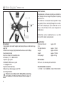
Model description:
1. Triple-axis gyro system, ensuring stable, accurate flight.
2. The high-performance brushless motor provides ample power
for advanced 3D flying.
3.FUTABA S-FHSS receiving system for binding to all current
FUTABA S-FHSS transmitters.
4. This helicopter is capable of indoor flight times of around 6 to
7 minutes with a fully charged battery.
5.The ideal model for pilots who have experience flying collective-pitch helicopters.
Please note the following points in order to avoid confusion
in the model description:
The model's nose faces away from the pilot; the tail boom points
towards the pilot. The pilot's left-hand side is the left-hand side of
the model, and the pilot's right-hand side is the right-hand side of
the model. The rotor head faces up, and the landing skids face
down (see illustration).
right
top
front
rear
bottom
left
Operating Instructions - SOLO PRO 229 EC145 Police FTR RTB 2.4 GHz No. NE3524RTB
SOLO PRO 229 EC145 Black FTR RTB 2.4 GHz No. NE3525RTB
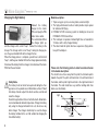
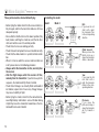
Collective pitch and throttle settings
(Recommended transmitter programming)
Overview of rotor control system
Normal flight
Pitch-axis
servo
Roll servo
Stick position, low:
Throttle 0%,
collective pitch -3°
Throttle
Stick position, middle:
Throttle 70-75%,
collective pitch +3°
Collective
pitch servo
Throttle
curve
(Normal)
Stick position, high:
Throttle 100%, collective pitch +10°
front
Overview of receiver channel assignment
Roll servo
Pitch-axis servo
Speed controller
Main motor
Main motor
LiPo battery
Collective
pitch servo
Speed controller
Tail rotor motor
Tail rotor motor
3D flying
Stick position, high:
throttle 100%,
collective pitch +13°
Collective pitch
Collective
pitch curve
(Normal)
Throttle
Collective pitch
Stick position, middle:
Throttle 100%,
collective pitch 0°
Throttle (3D)
Stick position, low:
Throttle 100%,
collective pitch -13°
Collective
pitch (3D)
9
Preparing the transmitter, using the Futaba T8J as an example:
- Set S-FHSS modulation
- The transmitter must be set to swashplate mode H-1 (see T8J instructions, 8.1 Parameter, page 38)
Please note:
1. The model must stand on a level surface during the initialisation process.
2. Always switch the transmitter on first, and only then the receiver.
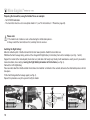
Installing the flight battery
Move the collective pitch / throttle stick and trim to their lowest position. Switch the transmitter on.
Withdraw the front fuselage fairing, and insert the charged LiPo flight battery in the battery frame in the helicopter (see Figs. 1 and 2).
Support the model at the marked point (main rotor axis) and allow it to hang freely. Ideally it will now balance exactly level. If you need to
make corrections, do so only by moving the flight battery forward or aft in the frame (see Fig. 3).
Connect the LiPo flight battery.
Take care not to touch the throttle control. Do not move the model for a minimum of five seconds, otherwise the initialisation process will not
take place.
Fit the front fairing onto the fuselage again (see Fig. 4).
Repeat this procedure every time you wish to fly the model.
1
10
2
3
4
Operating Instructions - SOLO PRO 229 EC145 Police FTR RTB 2.4 GHz No. NE3524RTB
SOLO PRO 229 EC145 Black FTR RTB 2.4 GHz No. NE3525RTB
Binding the transmitter to the model:
- Switch the transmitter on, then connect the flight battery.
- Locate the T-button (binding button) and hold it pressed in for about three seconds.
- If initialisation (binding) is successful, the receiver's status LED glows constantly.
- Binding is retained when the system is switched off. The procedure only needs to be repeated if you replace the
receiver or transmitter
T
S
Transmitter adjustment facilities:
Setting up a throttle curve: to program the throttle curves, please follow the description in the instructions supplied with your T8J radio
control system (8.2 Programming the throttle curve (THR CURVE), page 40).
Setting up a collective pitch curve: to program the collective pitch curves please follow the description in the instructions supplied with
your T8J radio control systems (8.9 Setting collective pitch travel (COLL TRAVEL), page 47)
Setting tail rotor gyro gain: to adjust the gain of the tail rotor gyro please follow the description in the instructions supplied with your T8J
radio control system (8.5 Gyro (gyro gain), page 44)
11
These points must be checked before flying:
- Before flying the model check that the receiver battery is
fully charged, and that the transmitter batteries still have
adequate capacity.
- Ensure that the throttle stick is at the lowest position (fully
back) before switching the model on, and that all other
sticks and switches are in the normal position.
- Check that all servos are working perfectly.
- Check that each component has been installed correctly.
- Check that the whole model is in perfect technical condition.
- When it is time to switch the receiver and transmitter on
or off, please observe the following procedure:
- Always switch the transmitter on first, and only then
the receiver.
- After the flight always switch the receiver off first,
and only then the transmitter. If you fail to keep to this
sequence, the model could fly off out of control.
- Check that all linkages are correctly fitted and devoid of
lost motion; replace them if necessary. Sloppy linkages
may cause instability in flight.
- Before flying the model, check that the connection between flight battery and model is secure. Vibration during
a flight may cause the connectors to work loose; the model would then be out of control.
12
Controlling the model
Mode 1
Mode 2
Roll:
If you move the roll
stick to left or right,
the helicopter flies
in the corresponding
direction.
Climb / descent:
When you move the
throttle stick up or
down, the helicopter
climbs or descends.
Yaw:
If you move the tail
rotor stick to left or
right, the helicopter
rotates in the corresponding direction.
Pitch-axis:
If you move the
pitch-axis stick up or
down, the helicopter
will fly forward or
back.
Operating Instructions - SOLO PRO 229 EC145 Police FTR RTB 2.4 GHz No. NE3524RTB
SOLO PRO 229 EC145 Black FTR RTB 2.4 GHz No. NE3525RTB
Important Notes
The first few flights
Take-off: raise the rotor speed slowly and steadily until the model hovers at eye-level. At low height (approx. 10 - 15 cm above
the ground) the model cannot be trimmed accurately due to the
turbulence generated by the rotor.
Ideally the first flight should take place in a large indoor space
devoid of obstructions. If you have to fly the model in the open air,
wait for a day with totally flat calm conditions. We recommend
that you ask an experienced helicopter pilot to help you during
the first few flights.
Landing: slowly and steadily reduce the throttle setting until the
model descends and touches down. Never reduce the throttle
setting abruptly.
After the landing disconnect the flight battery from the receiver,
and only then switch the transmitter off.
Caution: stopping (obstructing) the rotor blades when they are
turning can cause serious damage to the mechanical system,
and may even result in a fire. Immediately move the throttle stick
to Idle if this should happen.
Note regarding the flight battery: as soon as you notice a reduction in motor power, land immediately and disconnect the battery. Never continue flying until the battery is flat, as this causes
a deep-discharge condition which results in permanent damage.
Allow the battery to cool down before recharging it.
Replacing the rotor blades: if a rotor blade is damaged, replace
it immediately. When fitting the new rotor blade, tighten the retaining screw just to the point where the blade still swivels smoothly.
Pilot
Pilot
Pilot
Once the model is properly trimmed, you can practise hovering,
and carry out manoeuvres such as circles, squares, rectangles
and figures-of-eight. Initially it is always best to stand about two
metres away from the model, behind or at right-angles to it; this
avoids giving incorrect control commands. You can fly a square
pattern by alternating the direction of flight: away from the pilot, to
the pilot's right, and then towards the pilot again.
Important: Check the state of charge of the transmitter batteries before each flight, and recharge them when necessary.
It is essential to charge the flight battery before every flight.
Tip: when the helicopter is flying with the nose pointing towards you, the controls are reversed (apart from the throttle
control).
13
NE252401
NE252402
NE252403
NE252404
NE252405
NE252406
NE252407
NE252408
NE252409
NE252411
NE252413
NE252414
NE252415
NE252416
NE252417
NE252418
NE252419
NE251220
NE252421
NE251563
NE252423
NE252424
NE252425
NE252426
NE252427
NE480064
NE200113
NE200120
14
Operating Instructions - SOLO PRO 229 EC145 Police FTR RTB 2.4 GHz No. NE3524RTB
SOLO PRO 229 EC145 Black FTR RTB 2.4 GHz No. NE3525RTB
Replacement Parts list - SOLO PRO 229 EC145 Police FTR RTB Replacement Parts list - SOLO PRO 229 EC145 Black FTR RTB
Order No.
Description
NE252401
Front cabin section
NE252402
Rear cabin section
NE252403
Fuselage tail boom
NE252404
Vertical stabiliser
NE252405
Main rotor blades
NE252406
Tail boom unit
NE252407
Tail rotor blade
NE252408
Servo mount set
NE252409
Main rotor blade holder
NE252411Swashplate
NE252413
Lower pushrod set
NE252414
Main frame
NE252415
Main gearwheel
NE252416
Landing gear mount
NE252417
Landing gear
NE252418
Rotor head, metal
NE252419
Blade feathering spindles
NE252420
Main rotor shaft
NE252421
Screw set
NE251563
BL main motor
NE252423
BL tail rotor motor
NE252424
LiPo battery, 11.1 V / 800 mAh
NE252425Receiver
NE252426
BL speed controller, main motor, 20 A
NE252427
BL speed controller, tail rotor motor, 5 A
NE480064
NES 8 g digital servo
NE200113
Battery charger
NE200120
Mains PSU
Order No.
NE352501
NE352502
NE352503
NE352504
NE352505
Description
Front cabin section, black (not shown)
Rear cabin section, black (not shown)
Fuselage tail boom, black (not shown)
Vertical stabiliser, black (not shown)
Tail boom unit, black (not shown)
When replacing components it is very important to use
the correct tool and to tighten the screws with great care.
Do not use thread-lock fluid!
15
robbe Modellsport GmbH & Co. KG hereby declares that this device conforms to the fundamental requirements and other relevant regulations
of the corresponding EC Directive. You can read the original Conformity Declaration on the Internet at www.robbe.com: click on the "Conformity Declaration" logo button which you will find next to the corresponding device description.
This symbol means that you should dispose of electrical and electronic equipment separately from the household waste when it reaches the
end of its useful life. Take your unwanted equipment to your local council collection point or recycling centre. This requirement applies to member countries of the European Union as well as other non-European countries with a separate waste collection system.
Disposal of batteries
Batteries must not be discarded as domestic refuse. To protect the environment, always return exhausted or defective cells to your local recycling centre. These include retail sales outlets for batteries, and communal toxic waste disposal centres. Cover any bare wires with insulating
tape in order to avoid short-circuits.
robbe Modellsport GmbH & Co.KG
Metzloserstraße 38 · D-36355 Grebenhain
Technical hotline: +49 (0)66 44 / 87-777 · [email protected]
Commercial register: Gießen Regional Court HRA 2722
Partner with personal liability:
robbe Modellsport Beteiligungs GmbH Gießen / HRB 5793 · Managing Director: E. Dörr
Errors and technical modifications reserved. - Copyright robbe-Modellsport 2014
Duplication and copying of the text, in whole or in part, is only permitted with the prior written approval of robbe-Modellsport GmbH & Co. KG
16