1
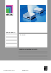
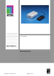
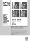
7320.790
Automatic Door
Control Unit
Assembly and operating instructions
A4069307IT74
Contents
Contents
1
EN
Notes on documentation.................................... 2
1.1
CE labelling.................................................. 2
1.2
Storing the documents................................. 2
1.3
Used symbols and technical terms.............. 2
1.4
Other applicable documents ........................ 2
2
Safety instructions ............................................. 2
2.1
3
Generally applicable safety instructions ...... 2
Device description ............................................. 3
3.1
Components and function description ......... 3
3.1.1
Automatic Door Control Unit .................. 3
3.2
Proper use ................................................... 4
3.3
Dimensions .................................................. 4
3.4
Scope of delivery ......................................... 4
4
Assembly and installation .................................. 4
4.1
Assembly procedure .................................... 4
4.2
Installation.................................................... 5
4.3
Installation procedure .................................. 5
4.3.1
Automatic Door Control Unit wiring ....... 5
4.3.2
Installation guidelines ............................ 7
5
Commissioning and configuration ..................... 7
6
Operation ........................................................... 8
6.1
Display elements ......................................... 8
6.2
Error messages ........................................... 8
7
Fault and remedial action .................................. 8
8
Inspection and maintenance.............................. 8
8.1
Inspection .................................................... 8
8.2
Maintenance ................................................ 8
8.3
Software updates......................................... 8
9
Storage and disposal ......................................... 8
10
Technical specifications..................................... 9
11
Spare parts ........................................................ 9
12
Wiring diagrams................................................. 9
13
Glossary............................................................. 9
14
Customer service addresses ............................. 9
Automatic Door Control Unit
1
EN
1 Notes on documentation
1
Notes on documentation
These instructions are intended for trained specialists
who are familiar with the assembly, installation and
operation of the system. Read these operating
instructions prior to commissioning and be sure to
keep them accessible for later use. RITTAL can
accept no liability for damage and operating problems
resulting from non-compliance with these instructions.
1.1 CE labelling
The Control Unit satisfies the CE conformity
requirements of the EMC Directive 2004/108/EU. The
declaration of conformity can be requested from Rittal
Service.
1.2 Storing the documents
These instructions and all associated documents
constitute an integral part of the product. They must
be given to the device operator. The operator shall be
responsible for storage of the documents, to ensure
that they are readily available when needed.
1.3 Used symbols and technical terms
The signal word classifies the effects of a danger in
case of the non-observance of the safety instructions.
A differentiation is made between:
– Danger
A dangerous situation for which the failure to comply
to this note causes death or severe injury.
– Warning
A dangerous situation for which the failure to comply
to this note can cause death or severe injury.
– Caution
A dangerous situation for which the failure to comply
to this note can cause (minor) injuries.
– Note
Identification of situations that can cause material
damage.
The signal words are shown in the following form in
the instructions:
e.g.
Signal word!
1. Description of the danger and its
effect
2. Description of the behaviour of the
user to prevent danger
2
Automatic Door Control Unit
1.4 Other applicable documents
In conjunction with these operating and installation
instructions, reference is also made to the operating
and installation instructions for the CMC-TC
Processing Unit II and to the operating and
installation instructions for the products listed in
Section
3.1. are contained on the CD-ROM that
All
documents
accompanies the Processing Unit II.
The appropriate current version can be downloaded
as PDF file from the RITTAL homepage
http://www.rittal.com/.
2
Safety instructions
2.1 Generally applicable safety instructions
Please observe the following general safety
instructions when installing and operating the system:
- The assembly and the installation of the system,
in particular the wiring of enclosures with mains
power, may be performed only by a trained
electrician.
- Observe the valid regulations for the electrical
installation for the country in which the system is
installed and operated, and the national
regulations for accident prevention. Also observe
any company-internal regulations (work,
operating and safety regulations).
- Use only original RITTAL products or products
recommended by RITTAL in conjunction with this
product.
- Do not make any changes to this product other
than those described in these or associated
operating and installation instructions.
- The operational safety of the product is
guaranteed only for its approved use. Under no
circumstances should the technical data and the
specified limit values be exceeded. This is
especially true for the specified ambient
temperature and IP protection category.
- The Control Unit must not be opened. The unit
does not contain any parts that need servicing.
- Operating the system when it is in direct contact
with water, corrosive substances or flammable
gases and vapours is prohibited.
- The CMC-TC system must be disconnected from
the power supply when the Control Unit is
connected with an I/O unit, a Basic CMC or an
LCP system.
- Other than these general safety notes, ensure
you also observe the specific safety notes when
the tasks described in the following chapters are
performed.
3 Device description
3
EN
Device description
3.1 Components and function description
3.1.1 Automatic Door Control Unit
All inputs and outputs of the Automatic Door Control
Unit are located on the rear.
The following components belong to the complete
Automatic Door Control system:
Designation
Automatic Door Control Unit
Up to four Automatic Door Kits
Up to four Automatic Door keys
Up to four TS 8 comfort handles
with door opener function
230 V / 24 V power pack with
connection cable
Fastening components in the 19"
frame
Fastening components in the
enclosure frame
Order number
7320790
7320.792, or 7320.795,
or
7320.796
7320.793
7320.794
7320.725
7200.210
7320.440
7320.450
The Automatic Door Control Unit performs the
automatic opening of the rack doors should the
cooling system of the racks fail or the rack doors
need to be opened because of a smoke alarm and
fire extinguishing so that the extinguishing gas
entering the room can penetrate the racks.
The Control Unit can activate as many as four
Automatic Door Kits for the control of a maximum of
four doors where the CMC-TC system can always
control two doors using one CMC-TC channel. In
addition, four normally-closed contacts are provided
that can be assigned individually and connected to
their manually initiating keys or other adequate
switching elements. The Automatic Door Control Unit
receives an identification so it can be automatically
detected and set up by the CMC-TC system.
The Automatic Door Kit provides the magnetic locking
of the rack doors that is activated by the Automatic
Door Control Unit.
The holding magnets of the Automatic Door Kit in
their active state are supplied with 24 V power. When
the command for opening the door is issued, the
Automatic Door Control Unit deactivates the magnets
and the installed gas pressure dampers open the
rack doors.
Automatic Door Control Unit
Fig. 1: Automatic Door Control Unit – rear trim panel
Legend
I/O Door 1/2 or 3/4:
Two RJ12 sockets for connection to an I/O unit
of a CMC-TC system.
The input 1/2 and input 3/4 activates Doors 1
and 2, and Doors 3 and 4, respectively.
The CMC-TC Processing Unit II can be used to
define the appropriate combinations that cause
the doors to be opened in an alarm situation.
The Automatic Door Unit can be activated by a
CMC-TC I/O unit in conjunction with a PU II or
alternatively by a Basic CMC.
Doors 1, 2, 3, 4:
Four terminals for up to four door locks
(Automatic Door Kits)
The following assignment is recommended:
Door 1: Rack 1 front door
Door 2: Rack 1 rear door
Door 3: Rack 2 front door
Door 4: Rack 2 rear door
Access – Input 1, 2, 3, 4:
Four connections for Access Input components.
A channel for the manual door opening is
provided for each door. Automatic Door keys or
TS 8 comfort handles with door opener function
are connected to open the doors manually.
Power:
Connection for the 24 V power supply.
3
EN
4 Assembly and installation
3.2 Proper use
Assembly in the 19" frame with 7320.440:
The Automatic Door Control Unit may only be used
for the automatic opening of the TS 8 rack doors in
an emergency situation.
Other applications other than those mentioned in this
manual are expressly not permitted.
Warning!
The system may not automatically
activate any door systems that exhibit
dangerous door forces that can injure
persons in any manner.
Only the RITTAL Automatic Door Kit
product may be activated.
Fig. 3: 19" attachment
Mounting module with CMC 7320.450
3.3 Dimensions
W x H x D: 136 mm x 44 mm x 129 mm
3.4 Scope of delivery
1x
1x
2x
2x
4
Automatic Door Control Unit
Assembly, installation and operating instructions
Nylon tape fastening
RJ12 connection cable
Assembly and installation
The Automatic Door Control Unit is installed in a
RITTAL TS 8 rack in accordance with the procedure
described below.
4.1 Assembly procedure
Assembly with nylon loop fastening:
Fig. 4: Enclosure assembly with 7320.450
Fig. 2: Nylon loop fastening
4
Automatic Door Control Unit
4 Assembly and installation
Connection of the Automatic Door Control Unit to a
Basic CMC or an LCP Plus Control Unit
4.2 Installation
Warning!
The system operates only with safety
extra-low voltage.
Under no circumstances may voltages
higher than those prescribed be
connected to the system. Lethal
danger!
EN
Connect the inputs from Door 1/2 and Door 3/4 with
any free port on the Basic CMC as shown in Fig. 6.
Use the RJ12 cable provided for this purpose.
Door 1/2 to Port 1
Door 3/4 to Port 2
4.3 Installation procedure
Once all system components have been installed in
accordance with the associated installation
instructions, the installation as described below is
performed.
Note!
For the installation, the system must
remain disconnected from the power
supply for the complete time.
Otherwise defects can occur to the
unit.
4.3.1 Automatic Door Control Unit wiring
P-I2C
7320.110
Fig. 6: Automatic Door Control Unit with Basic CMC
Note!
The maximum signal cable length of
6 m must not be exceeded.
Connection of the Automatic Door Control Unit to the
CMC-TC I/O unit.
Connect the inputs from Door 1/2 and Door 3/4 with
any free port of the CMC-TC I/O unit as shown in
Fig. 5. Use the provided RJ12 cable for this purpose.
Connection of the Automatic Door Kits
As many as three holding magnets can be connected
to the Door 1-4 outputs.
Connect the Automatic Door Kits as shown in Fig. 7.
Door 1: Rack 1 front door
Door 2: Rack 1 rear door
Door 3: Rack 2 front door
Door 4: Rack 2 rear door
Door 1/2 to Port 1; Door 3/4 to Port 2
1
2
3
4
I/O
7320.210
Fig. 5: Connection to the CMC-TC I/O unit
Fig. 7: Connection of the holding magnets of the Automatic Door
Kits
Automatic Door Control Unit
5
EN
4 Assembly and installation
Connection of the Automatic Door key 7320.793
or alternatively the comfort handle with door
opener function 7320.794
Connection of the 24 V power supply
Remove the jumpers at the connection terminals
Access – Input 1-4.
Connect the Automatic Door keys as shown in Fig. 8.
7320.425
Fig. 10: 24 V power supply
Fig. 8: Connection of Automatic Door keys
The keys can be placed anywhere. We recommend
that the keys are placed where they are easily
accessible provided there is no danger of them being
activated inadvertently. The maximum cable lengths
must not be exceeded.
Fig. 9: Automatic Door Control Unit with TS 8 comfort handle with
door opener function
6
Automatic Door Control Unit
Note!
We recommend that the doors are
monitored with access sensors
(7320.530) because the Automatic Door
Control Unit does not provide this
function.
5 Commissioning and configuration
4.3.2
Installation guidelines
Note!
The installation guidelines described
below are based on a risk analysis for
the Automatic Door Control system
and must always be observed in order
to ensure the highest possible
functional reliability not only in normal
operation but also in a fault situation.
1st The Automatic Door Control system must be
compatible to the controlling system should
the power fail.
If the Automatic Door Control system is used in
combination with an LCP system, both systems
must be connected to the same power supply. If
the fan motors of a connected 3-phase LCP
system are connected to a phase, the power
supply of the Automatic Door Control system
must be connected to the same phase as the
fan
motors.
If
the
Automatic Door Control system is
controlled from a Processing Unit, both systems
must be connected to the same power supply.
2nd The rack doors must always be able to be
opened manually at anytime using an
Automatic Door key or TS 8 comfort handle
with door opener function.
Please always install one of the named options.
3rd Rack doors must not open inadvertently.
If the 24 V power supply to the Automatic Door
Control Unit fails, the rack doors will open. Use
the alarm configuring of the PU II or the Basic
CMC to ensure that in this case all required
protective measures are initiated for the installed
server systems.
4th Rack doors must not remain closed in a fault
situation.
The connected controller must be configured so
that the relevant alarms are signalled and
manual intervention is possible.
To ensure the continuing correct functioning of
the system, the correct functioning of the
Automatic Door Control system must be checked
in its full scope once after successful installation
and then in regular time intervals.
Automatic Door Control Unit
5
Commissioning and configuration
EN
After the successful installation and the connection to
the mains voltage, the Automatic Door Control
system must be configured. This is done from the
Processing Unit website as shown in Fig. 11.
Fig. 11: Automatic Door Control System website
Legend
- Output status:
Current status of the door opening magnets.
- Message text:
Specific text.
- Delay:
Power-on delay for the door opening magnets.
- Time-out:
Definition of the state the Automatic Door Control
system should assume after switch-off and -on.
- Trap receiver:
Activation of up to three SNMP trap messages.
- Send SMS, send e-mail:
Activation of SMS and e-mail messages in a fault
situation.
- Switch output:
Activation/deactivation of the door opening
magnets.
- Accept:
Confirmation of the configuration input.
- Reset:
Reset the configuration to the default values.
- Combinations:
Calling the "Combinations" menu. See Fig. 12.
7
EN
6 Operation
-
7
Fault and remedial action
Malfunction
Doors cannot be closed
Fig. 12: Combinations website
Combinations can be used to combine the status of
the connected sensors and group them to form
dedicated status messages.
Doors remain closed in the
"Open" system status
8
6
Operation
The Automatic Door Control Unit does not have any
control elements.
6.1 Display elements
Remedy
Check the miniature fuses in
the Automatic Door Control
Unit
Check the power supply of
the Automatic Door Control
Unit
Check alarm messages and
"Combinations"
Check the plugs at the
"Access Units" inputs and
the "Doors" outputs
Check the cabling, in
particular the connection
cable from the Processing
Unit or the LCP Controller to
the Automatic Door Control
Unit.
Inspection and maintenance
8.1 Inspection
The system must be checked regularly for its
complete correct functioning. RITTAL recommends a
regular function test when required, but not in
intervals longer than one year.
8.2 Maintenance
The system does not require any maintenance.
8.3 Software updates
Fig. 13: Automatic Door Control Unit – display elements
Legend
The following display elements are located on the
front of the Automatic Door Control Unit:
- Doors 1/2 F1:
1.5 A miniature fuse, 20 mm slow for Automatic
Door Kits 1 and 2.
- Doors 3/4 F1:
1.5 A miniature fuse, 20 mm slow for Automatic
Door Kits 1 and 2.
- Power 1:
Automatic Door Kit 1/2 switched on/off.
- Power 2:
Automatic Door Kit 3/4 switched on/off.
- Doors 1, 2, 3, 4:
- Automatic Door Kits are activated/deactivated.
The doors can be closed. The display is not
affected by operating the Automatic Door keys or
the TS 8 comfort handle.
6.2 Error messages
All error messages are issued from the Processing
Unit or the Basic CMC.
8
Automatic Door Control Unit
At the time of performing the installation, check that
the Processing Unit, the Basic CMC and the LCP
controller have the latest software version.
9
Storage and disposal
Please dispose of as electronic scrap and observe
the country-specific regulations.
10 Technical specifications
10 Technical specifications
11 Spare parts
Designation
Miniature fuses, type 5 x 20 mm, 1.5 A slow.
The product will be replaced in case of an Automatic
Door Control Unit defect.
Enclosure
Housing type
Height
Width
Depth
Weight without
packaging
Potential equalisation
Earthing
Protection category
Interfaces
LED display
Door outputs
Normally closed
contacts
Operational area
Temperature
Humidity
Storage temperature
Rated voltage
Fuses
Automatic Door Control
Unit
Plastic coating with metal
trim
1 U (44.5 mm)
136 mm
129 mm
approx. 0.6 kg
- 1)
- 1)
IP 40 according to
EN 60529
2x, Power Control
4x, Doors Status
4x, max. 24 V DC, 400 mA
4x, max. 30 V DC, 1 A
+5° to +45°C
+42° to +113°F
5 – 95%
-20° to +60°C
-4° to +140°F
1 x 24 V DC,
2.0 A SELV
1.5 A miniature fuse, slow,
UL approval
2 x RJ-12 sockets
EN
12 Wiring diagrams
A Word template for creating circuit diagrams can be
downloaded from the RITTAL homepage
www.rittal.com. This template allows all products of
the CMC-TC system to be represented and
integrated in circuit diagrams.
13 Glossary
CMC: Computer Multi Control
CMC-TC: Computer Multi Control – Top Concept
CU: Control Unit (Automatic Door Control Unit)
PU II: Processing Unit II
14 Customer service addresses
If you have technical questions, or
questions regarding our product range,
please contact the following service contact:
Tel.: +49 (0)2772/505-1855
http://www.rittal.com
E-mail: [email protected]
CMC-TC connection
Maximum cable length
CU to I/O unit
10 m, after consultation
with Rittal, up to 50 m,
UL approval
CU to Basic CMC
10 m, after consultation
with Rittal, up to 50 m,
UL approval
CU to LCP Plus
10 m, after consultation
with Rittal, up to 50 m,
UL approval
1)
Not required because 24 V DC safety extra-low voltage
Automatic Door Control Unit
9
Schaltschrank-Systeme
Industrial Enclosures
Coffrets et armoires électriques
Kastsystemen
Apparatskåpssystem
Armadi per quadri di comando
Sistemas de armarios
Stromverteilung
Power Distribution
Distribution de courant
Stroomverdeling
Strömfördelning
Distribuzione di corrente
Distribución de corriente
Elektronik-Aufbau-Systeme
Electronic Packaging
Electronique
Electronic Packaging Systems
Electronic Packaging
Contenitori per elettronica
Sistemas para la electrónica
System-Klimatisierung
System Climate Control
Climatisation
Systeemklimatisering
Systemklimatisering
Soluzioni di climatizzazione
Climatización de sistemas
IT-Solutions
IT Solutions
Solutions IT
IT-Solutions
IT-lösningar
Soluzioni per IT
Soluciones TI
Communication Systems
Communication Systems
Armoires outdoor
Outdoor-behuizingen
Communication Systems
Soluzioni outdoor
Sistemas de comunicación
Rittal GmbH & Co. KG · Postfach 1662 · D-35726 Herborn
Telefon +49(0)2772 505-0 · Telefax +49(0)2772 505-2319 · eMail: [email protected] · www.rittal.de