1
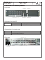
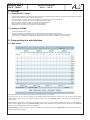
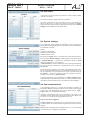
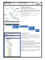
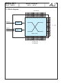
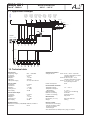
Professional Headend Solutions Operating instructions SAT-IF ROUTER SAT IF → SAT IF SMA 001 Part No: 7905.81 SMA 001 Part N : 7905.81 o SAT-ZF ROUTER SAT IF → SAT IF Contents 1. Safety and operating instructions................................................................................................................ 3 2. Device variants ........................................................................................................................................... 3 3. General ......................................................................................................................................................... 3 4. Features ....................................................................................................................................................... 3 5. Functional description................................................................................................................................... 3 6 Explanation of the operating elements ....................................................................................................... 4 6.1 Front view .................................................................................................................................................... 4 6.2 Meaning of the Status LED .................................................................................................................... 4 6.3 Explanations of the function keys ......................................................................................................... 4 6.4 Rear view .................................................................................................................................................... 4 7. Adjustments ................................................................................................................................................. 5 7.1 Adjustment with the PC/ laptop.............................................................................................................. 5 7.2 Adjustment with SNMP........................................................................................................................... 5 8. Programming by web server ........................................................................................................................ 5 8.1 Main menu ............................................................................................................................................. 5 8.2 Edit labels .............................................................................................................................................. 6 8.3 System settings ..................................................................................................................................... 6 8.4User administration................................................................................................................................ 6 9. SNMP management...................................................................................................................................... 7 9.1 Management Information Base (MIB).................................................................................................... 7 9.2 Download MIB........................................................................................................................................ 7 9.3 SNMP management software................................................................................................................. 7 10. Block diagram ........................................................................................................................................... 8 11. Application example.................................................................................................................................... 9 12. Technical data ............................................................................................................................................ 9 13. Glossary ................................................................................................................................................... 10 14. Bibliography ..... ....................................................................................................................................... 10 15. Document history ..................................................................................................................................... 10 Declaration of Conformity ......................................................................................................................... 11 2 SMA 001 Part N : 7905.81 o SAT-ZF ROUTER SAT IF → SAT IF 1. Safety and operating instructions When insstalling, starting-up and adjusting the device, it is necessary to consider the system specific references in the instruction manual. The device may only be installed and started up by authorized technical personnel. When installing the device into the receiving points, the adherence of the EMC regulations is to be ensured. The assembly and wiring have to be done without voltage. With all work the defaults of the DIN EN 50083 have to be considered. It is especially important to follow DIN EN 60728-11 [1]. The devices come under protection classification I. It is absolutely necessary, therefore, to insert the mains plug into a socket with protective contact. WEEE-Reg.-Nr. DE 50389067 2. Device variants SMA 001 SMA 001 SMA 001 7905.81 7905.82 7905.83 SAT IF → SAT IF, 90 ... 240 V power supply SAT IF → SAT IF, 48 V DC port SAT IF → SAT IF, 12 V DC port 3. General The SAT-IF ROUTER SMA 001 is a device of the headend system A-LINE, which is conceived as a complete system for big and middle sized networks. The SMA 001 is a controllable signal switch for the satellite IF range. The device is a independently operating unit in 19 “ rack (2 RU). The power supply is redundant as a wide-range power supply. The 48 V version is also redundant. The SMA 001 has 16 signal inputs and 16 signal outputs. Via the web interface, any input signal can be routed to any output. At the same time, the input signals are also permanently at 16 loop outputs for further use. Thus, this module can optimally be used as a remotecontrolled satellite IF signal source selector for the individual supply of terminal equipment, e.g. redundancy assemblies. 4. Features • signal source switch for headends • SAT IF router: routs 16 inputs to 16 outputs free selectable • cascadable system • IP-based controlling via integrated web server • supports SNMP version 1 • 19 “ 2 RU stand-alone device 5. Functional description With the SAT-IF ROUTER SMA 001 each of the 16 switching outputs can be routed to any of the 16 inputs for the frequency range 950 up to 2150 MHz. The 16 inputs are grouped into four groups each with 4 inputs. Usually every input is assignable to arbitrary SAT-IF signals. Each of these groups can supply a LNB with fixed 12 V. The power is switched via software per group and electronically secured. The 16 input signals are available at 16 further outputs for cascading other boards. The controlling of the device is via Ethernet 10 Mbit (HTML, SNMP version 1). 3 SMA 001 Part N : 7905.81 SAT-ZF ROUTER SAT IF → SAT IF o 6. Explanation of the operating elements 6.1 Front view POWER-LED SAT-IF output 1 .... 16 CONTROL port IP-DEFAULT RESET button 6.2 Meaning of the status LED Designation (Colour) Status Meaning of display Power (green) permanently on Device is working off Device is off, without current supply 6.3 Explanations of the function keys Key Function RESET Reboot the device and setting the stored values IP-DEFAULT Resets the device back to the default IP address 192.168.2.80. Hold the key down until POWER LED signals the transfer (after approximately 25 s). 6.4 Rear view POWER ground terminal (redundancy) SAT-IF input 1 ... 16 loop SAT-IF output 1 ... 16 4 SMA 001 Part N : 7905.81 SAT-ZF ROUTER SAT IF → SAT IF o 7. Settings 7.1 Setting via PC/ laptop · for the remote programming an internet connection according to IP standard and an ethernet connection to the PC/ laptop is required ·program the provided IP address (default: 192.168.2.80) ·if there is a direct connection between PC and SMA 001, please use a crossover cable (RJ 45) ·if connected via hub, please use a normal straight throught patch cable ·start-up the HTML browser and enter the IP address as target address ·after successful connection the web interface will be displayed ·all adjustments of the device are specified on the web interface 7.2 Setting via SNMP · · · · supported is SNMP version 1.0 [3] automatic gerneration of MIB based on the current headend configuration by the controller for setting and reading the parameters and to receive traps from an SNMP management software is required further notes on the SNMP functionality of BLANKOM modules are listed in the SNMP manual ( »chapter 9) 8. Programming via web interface 8.1 Main menu OK OK Generally, the device name and the item number are named at the top of the window. In the main menu you can select by clicking on the respective radio button which of the 16 inputs is to be routed to the associated output. Select for each of the 4 input systems whether a supply is input or not (Supply „on/off“). This applies to the terminals IN 01, 05, 09 and 13. Below the status of the PSU is diplayed. In the language option you can choose between English and German. The selection is to confirm with the “Apply“ button. The “Discard changes“ button resets all settings to the default settings. By pressing the “Refresh“ button, the current setting will be readout and displayed. “System settings“ opens the menu for network configuration ( »chapter 8.2). The button “Edit labels“ leads to the menu where the access rights are to be assigned. 5 SMA 001 Part N : 7905.81 o SAT-ZF ROUTER SAT IF → SAT IF 8.2 Edit labels In this menu the user can enter own notations in order to obtain a better overview of the system. The notations maximum length must be 21 charakters. This option exists either for the entire device for the 4 input systems as well as for each of the 16 inputs and outputs. By pressing the “Apply“ button these terms will be saved and displayed in the main menu.“Discard changes“ reset all settings to their default value. 8.3 System settings This configuration menu enables the adjustment of the IP address, the subnet mask and the gateway address of the device and thus an adaptation to the network of the user. Default: IP address: 192.168.2.80 Subnet mask: 255.255.255.0 Gateway address: 0.0.0.0 By clicking the „Apply“ button, the settings were saved and the device is set accordingly. “Discard changes“ reset all settings to their default value. • Download MIB File - is required for operating the device via SNMP, without the web browser ( »see chapter 9) • Data from Device - creates a backup file of the previously made settings that can be used as a template. It is important that the file is saved as filename.sma. All device settings, notations, user names and passwords are stored in this file except the administrator and the administrator password. In this way a configuration can be copied from one device to another easily. Via the „Browse ...“ button, it is possible to call such a template. If the file is selected, it must be sent by „Data to Device“. If unsaved changes have to be discarded, the “Factory settings“ button reset all settings to their default factory value. In addition, the MAC address of the device and the software version of the web server are displayed. 8.4 User administration In the registration menu up to 7 people can be created, in addition, an administrator must be specified. He has full access rights to make changes in this menu. User administration can only be edited with the „Login / Logout = off“ or as a registered administrator. Username and password must not be exceeded in their length of 16 characters and only alphanumeric values are permitted. User names must be unique, so no name may be assigned more than once. Only one user can be logged in! If Login / Logout „On“ (dropd down menu) is adjusted a logoff of the user is required. Users are not automatically logged out even if they close the program. Additionally an automatic logout is adjustable. After 10 -, 20 - or 30 minutes of inactivity the user is logged off automatically. 6 SMA 001 Part N : 7905.81 o SAT-ZF ROUTER SAT IF → SAT IF 9. SNMP Management 9.1 Management Information Base The MIB is a reference for all objects (parameter) in a configured network and has a tree structure. The figure shows the BLANKOM path as a section of the MIB tree. Each node in the MIB tree has a name and a number and can be clearly referenced as a list. From the position in the MIB tree, the following notation for the BLANKOM base OID (Object Identifier) gives: iso.org.dod.internet.private.enterprise.blankom.antennentechnik =1.3.6.1.4.1.16744.1 illustration above: BLANKOM-OID within the MIB tree illustration below: further course of the OID formation 9.2 Download MIB For downloading the complete MIB of a SMA 001, please load the menu „System Settings“ (»chapter 8.2) and click on „Download MIB“. With a MIB browser, this can be analysed and be used for the controlling of the device via a network or SNMP manager, which has SNMP V1. Passwords for the community are „private“. 9.3 SNMP management software The SNMP functionality of the SMA 001 are designed for integration into existing management structures. For these already exist sophisticated network resp. SNMP management software solutions. BLANKOM therefore does not provide its own SNMP management software. The SNMP management software includes tools for MIB loading und trap receiving, incl. evaluation (e.g. weighting by error priority, frequency etc.) and establishing of certain interactions (e.g. automatic administrator information) Comprehensive information on the functions of SNMP management software is beyond the scope of this documentation. It must therefore be refered to other sources of information, for example, [4]. 7 SMA 001 Part N : 7905.81 SAT-ZF ROUTER SAT IF → SAT IF o 10. Block diagram 16x SAT IN Ethernet Control T1...T16 Supply Power Supply Unit Switch matrix 16x SAT OUT (to cascade) 8 SMA 001 Part N : 7905.81 SAT-ZF ROUTER SAT IF → SAT IF o 11. Application example CONTROL SAT router Hotbird 13° east high band horizontal 1/ S01 Astra 19,2° east high band horizontal Astra 19,2° east low band vertical 1/ S02 1/ S03 F F Eurobird 9° east high band vertical 1/ S04 F Eurobird 9° east high band horizontal Astra 19,2° east low band horizontal 1/ S05 1/ S06 F F F Astra 19,2° east high band vertical 1/ S07 F IC04 KPKC503 9x reserve PSZ816 SMA 001 IN 8x reserve CONTROL OUT SMA 001 SAT-MATRIX 13x reserve MSR 017 ASB 100 450 IP number: 192.168.2.80 BEB 200 SSI108 2 Tr.69 IP 1.04 2 Tr.83 IP 1.05 ASI SSI108 1 DVB-S/S2 DVB-S/S2 Tr.81 Tr.67 IP ASI SSI108 1 DVB-S/S2 DVB-S/S2 Tr.93 2 Tr.65 Tr.95 1 DVB-S/S2 DVB-S/S2 1.03 ASI KPKC603 KPKC603 1600 IP 1.02 ASI 2 1.06 ASI SSI108 ASI SSI108 KPKC603 IP 1.01 CKB 100 1 DVB-S/S2 DVB-S/S2 KPKC603 IP 2 KPKC603 01 Tr.75 Tr.81 1X 1 DVB-S/S2 DVB-S/S2 Tr.99 2 Tr.101 X2 KPKC603 1 DVB-S/S2 DVB-S/S2 450 3X Tr.79 HCB 200 SSI108 BUK 896 BEB 200 IP ASI 2.04 IP ASI SSI108 SSI108 1 2 IP ASI SSI108 Res. Tr.97 2.05 1 2 DVB-S/S2 DVB-S/S2 Tr.10 DVB-S/S2 DVB-S/S2 2.06 IP ASI SSI108 Res. 2 Tr.87 Tr.115 Tr.103 2.03 1 DVB-S/S2 DVB-S/S2 2.07 ASI KPKC603 SSI108 2 Tr.113 Tr.107 IP ASI KPKC603 KPKC603 SSI108 2.02 1 DVB-S/S2 DVB-S/S2 KPKC603 IP ASI 2 KPKC603 2.01 1 DVB-S/S2 DVB-S/S2 KPKC603 IP 2 KPKC603 02 Tr.85 Tr.71 1X 1 DVB-S/S2 DVB-S/S2 Tr.91 2 Tr.77 X2 Tr.89 1 DVB-S/S2 DVB-S/S2 450 3X SSI108 12. Technical data SAT IF input Frequency range Connector Impedance Adaption LNB feed LNB power supply 950 … 2150 MHz F socket 75 Ω > 10 dB 4 blocks 4x 12 V/ max. 500 mA SAT IF output Connector Impedance Adaption Through loss Decoupling F socket 75 Ω > 10 dB 4 ... 8 dB 30 dB SAT IF matrix output Connector Impedance Adaption Through loss Decoupling F socket 75 Ω > 10 dB 4 ... 8 dB 30 dB Operating parameters Voltage/ current 7905.812x 90 ... 240 V~ 50/ 60 Hz including redundancy function protection class 1 7905.82 2x 48 V DC (36 ... 75 V) including redundancy function 7905.83 1x 12 V DC (11,5 ... 12,5 V) 2 loop through sockets Power consumption 35 W Environmental conditions Temperature range -10 ... +55 °C Temperature range for data keeping 5 ... 45 °C Relative humidity ≤ 80 % (non condensing) Method of mounting horizontal Location of mounting splash-proof and drip-prooft Miscellaneous Dimensions (l x w x h) 483 x 89 x 385 mm Weight 4,200 g Remote control Network connection (LAN/ WAN) Ethernet, 10 Base T Connector RJ 45 Delivery content 2x Power cord or 48 V plug 1x RJ45 connection cable 16x Terminal resistor 1x Mounting kit other accessories (for example 12 V plug) on request 9 SMA 001 Part N : 7905.81 o SAT-ZF ROUTER SAT IF → SAT IF 13. Glossary Deutsches Institut für Normung (German Institute for Standardization) Electromagnetic compatibility Europäische Norm (European Standard) European Telecommunications Standards Institute Hypertext Markup Language Hypertext Transfer Protocol Intermediate Frequency Internet Protocol Local Area Network Light Emitting Diode Low Noise Block Media Access Control Microcontroller Management Information Base Rack unit Simple Network Management Protocol Television Wide Area Network DIN EMC EN ETSI HTML HTTP IF IP LAN LED LNB MAC MC MIB RU SNMP TV WAN 14. Bibliography [1]EN 60728-11: Cable networks for television signals, sound signals and interactive services Part 11: Safety (IEC 60728-11:2005); German version EN 60728-11:2005 [2] EN 50083-2 : Cable networks for television signals, sound signals and interactive services Part 2: Electromagnetic compatibility for equipment, German version EN 50083-2:2006 [3]RFC 1157 Request for Comments (RFC): RFC Database URL: http://www.rfc-editor.org/rfc.html 15. Document history Version Date Modification Author 1.00 17.07.2012 Basic document Häußer 1.01 02.08.2012 Revision Häußer 1.02 19.09.2012 Revision, device variants Häußer 1.03 18.06.2014 Revision, chapter 9 added, manual matched to software 2.0 Appelfelder Options upon request. Changes due totechnical progress reserved. BLANKOM Antennentechnik GmbH Hermann-Petersilge-Straße 1 • 07422 Bad Blankenburg • Germany • Phone +49 (0) 3 67 41 / 60-0 • Fax +49 (0) 3 67 41 / 60-100 10 Declaration of Conformity The Manufacturer BLANKOM Antennentechnik GmbH ∙ Hermann-Petersilge-Str. 1 ∙ 07422 Bad Blankenburg ∙ Germany herewith declares the conformity of the product group Product name: SAT-IF ROUTER Type: SMA 001 7905.81, 7905.82, 7982.83 Product number: according to the following regulations EN 50083-2 [2] EN 60728-11 [1] (as far as relevant) and additional device-specific regulations, enclosed above, which these products are subjected to. Date: 17.07.2012 Signature: Dr. Piero Kirchner (Managing Director) 11