1
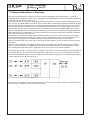
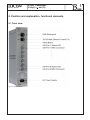
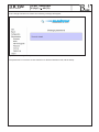
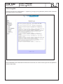
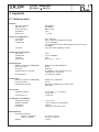
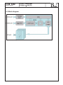
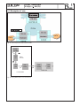
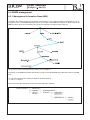
Professional Headend Solutions
Operating instructions
IP-ASI TRANSCODER
IP(GigE)
ASI(TS)
ITB 100
Part No: 9732.01
ITB 100
Part No: 9732.01
IP-ASI Transcoder
IP(GigE)
ASI(TS)
Table of content
1. Basic installing and operating instructions......................................................................................... 3
1.1 Safety instructions........................................................................................................................ 3
1.2 Contact
. ............................................................................................................................... 3
1.3 General description of functions................................................................................................... 4
1.4 Technical features and functions ................................................................................................. 5
2. Position and explanation, functional elements................................................................................... 6
2.1 Front view . ............................................................................................................................... 6
2.2 Functional elements . ................................................................................................................... 7
2.2.1 GbE streaming port ............................................................................................................ 7
2.2.2 10/100 Mbit control port...................................................................................................... 7
2.2.3 Reset button (sunk)............................................................................................................. 7
2.2.4 ASI-Ports (1...6).................................................................................................................... 7
2.2.5 AC power supply (mains connection)................................................................................. 8
3. Operating instructions......................................................................................................................... 9
3.1 Assembly and commissioning...................................................................................................... 9
3.2 Start-up behaviour........................................................................................................................ 9
3.3 Factory settings............................................................................................................................. 9
3.4 Settings via the HTML interface.................................................................................................. 10
3.4.1 Connection via the network to the Computer.................................................................... 10
3.4.2 System report.................................................................................................................... 12
3.4.3 Configuration..................................................................................................................... 13
3.4.3.1 Control port (10/100 port)...................................................................................... 14
3.4.3.2 Streaming port (GbE 1000 port)............................................................................ 15
3.4.3.3 Streaming configuration (ASI – GbE or GbE – ASI).............................................. 15
3.4.3.3.1 Notes on selection of IP addresses and UDP ports............................... 16
3.4.3.3.2 GbE-ASI streaming configuration (ASI output)...................................... 17
3.4.3.3.3 ASI-GbE streaming configuration (ASI input)........................................ 19
3.4.3.3.4 Changing the direction of streaming (ASI port data transfer direction).20
3.4.4 Administration and service................................................................................................ 21
3.4.4.1 Update................................................................................................................... 21
3.4.4.1.1 Firmware update.................................................................................... 22
3.4.4.1.2 Hardware update (FPGA)....................................................................... 26
3.4.4.2 ASI port upgrade..............................................................................................................28
3.4.4.3 Changing the password for the device................................................................. 30
3.4.4.4 Server administration............................................................................................. 32
3.4.4.5 Log file................................................................................................................... 34
4. Appendix
. ............................................................................................................................. 35
4.1 Technical data............................................................................................................................. 35
4.2 Block diagram............................................................................................................................. 36
4.3 Examples of use......................................................................................................................... 37
4.4 Forward error correction ............................................................................................................ 38
4.5 SNMP management.................................................................................................................... 39
4.5.1 Management Information Base (MIB)................................................................................ 39
4.5.2 Download of MIB / device management........................................................................... 40
4.5.3 Traps.................................................................................................................................. 40
4.5.4 SNMP management software............................................................................................ 41
4.6 Glossary
. ............................................................................................................................. 41
4.7 Bibliography............................................................................................................................... 42
4.8 History
. ............................................................................................................................. 42
2
ITB 100
Part No: 9732.01
IP-ASI Transcoder
IP(GigE)
ASI(TS)
1. Basic installing and operating instructions
1.1 Safety instructions
- When assembling and commissioning the ITB 100 IP-ASI Transcoder and executing the settings, always
follow the accompanying instructions exactly.
- The device is not to be assembled and brought into use by anybody who is not an authorised technician.
- When components are being installed in areas where reception is important, ensure that EMC regulations
are observed.
- All assembly, installation and cable connection must take place when no electricity has been connected.
- The provisions of DIN EN 50083 must be observed at all times when working with the equipment.
In particular, DIN EN 50083/1 regarding safety may on no account be ignored.
- The class of protection for the device is class II as per DIN EN 60065
1.2 Contact
If there are any questions or problems, help is available from
BLANKOM Antennentechnik GmbH
Hermann- Petersilge- Str. 1
07422 Bad Blankenburg
Germany
Telephone: Fax: +49 (0) 3 67 41 / 60-0
+49 (0) 3 67 41 / 60-100
Email: Web: [email protected]
www.blankom.de
3
ITB 100
Part No: 9732.01
IP-ASI Transcoder
IP(GigE)
ASI(TS)
1.3 General description of functions
This manual describes the use and functioning of the ITB 100 IP-ASI Transcoder (9732.01), a product of
BLANKOM Antennentechnik GmbH. For an explanation of the abbreviations IP and ASI and other abbreviations below, see the glossary, Section 4.6.
The transcoder is one component of the B-LINE head end system and it can receive a data stream in the variety of ways: by Gigabit Ethernet (in which case it outputs the IP encapsulated transport streams at the ASI
output ports) or by the reverse process, receiving the transport streams via the ASI input ports and sending
them on as a data stream via Ethernet. There are two Ethernet interfaces in the device. Both come in the
form of RJ45 sockets. The only Ethernet interface intended for the transport of MPEG data in accordance
with ETSI TS 102034 is the port designated as streaming port. This one is in GbE format (Gigabit Ethernet).
All IP data streams are unpacked in accordance with the protocol layers as they arrive and then forwarded
to the output port which has been set.
The first thing that happens to data streams at the ASI inputs is a check on their correctness. The system
then packs the TS (transport streams) to match the user’s settings and sends on the data packet thus formed via the streaming port. It is possible for both procedures (send and receive) to run at once.
At each of the ASI ports, there is an output step and an input equalizer. An LED for each port shows the current status.
There is a CPU monitoring and regulating all the internal procedures. It is possible to arrange the settings
either via a Web interface or via SNMP. The CPU has its own Ethernet interface, referred to as the control
port, which permits alteration of the configuration at any time, even during normal operation.
The ITB 100 transcoder can, at any one time, stream or receive up to 6 transport streams and place them at
the relevant ASI port. The process includes allocating a UDP port to a TS. It is also possible for each TS to
have its own IP address. There is a choice between UDP and RTP; the streams can be transported by either
or both methods to the various ports (Fig. 1).
Fig.1: Transport stream processing at the protocol level
If the transport is by RTP, it can be given forward error correction in accordance with the pro-MPEG Code of
Practice 3 rev. 2. How this works is shown in section 4.4.
4
ITB 100
Part No: 9732.01
IP-ASI Transcoder
IP(GigE)
ASI(TS)
1.4 Technical features and functions
The following are the technical features and/or functions of the ITB 100. For the technical data sheet, see
section 4.1.
- Bi-directional IP ó ASI converter
- Up to 6 ASI ports as per EN 50083-9
•Individually configurable as either input or output
•Configuration also possible during normal operation
•Allocation of IP encapsulated transport streams (TS) to the output ports as needed
- RJ45 connector to the GbE network for the data stream (this is the streaming port)
•DVB over IP to ETSI TS 102034 specifications
•UDP (user datagram protocol)
•RTP (real-time transport protocol)
•Additional variable forward error correction as per SMPTE2022 (COP3R2)
- RJ45 -10/100 Mbit network connection for control tasks (this is the control port)
- ASI inputs
•Individual data rates ranging from 1.3 to 139 Mbps.
•Burst mode or continuous mode
•Packet length 188/204 bytes
- ASI outputs
•Data rates ranging from 1.3 to 139 Mbps
•Burst mode
•Constant / variable bitrate, switchable
•Packet length 188 bytes
- Implemented servers (accessible via 10/100 Mbit control port)
•http server(s) (controlled via Web interface)
•SNMP server(s) (controlled via SNMP manager)
•DHCP client (integrated into existing IP infrastructure)
•NTP client for calibration of the internal Real Time Clock (RTC)
- Log-book
- Electricity supply voltage 100 to 240 V AC
- Assembly updatable from BLANKOM website
5
ITB 100
Part No: 9732.01
IP-ASI Transcoder
IP(GigE)
ASI(TS)
2. Position and explanation, functional elements
2.1 Front view
Fig. 2: Front view ITB 100
6
ITB 100
Part No: 9732.01
IP-ASI Transcoder
IP(GigE)
ASI(TS)
2.2 Functional elements
2.2.1 GbE streaming port
Two LEDs integrated into the RJ45 socket display the operating status of the streaming port:
LED
Function/Action
yellow
“Data” LED; flashes while data are being exchanged
green
“GbE Connect” LED; only shows when the GbE cable
connection is active (will not be illuminated if the
connection rate is 10/100 Mbit).
Table 1: LED demonstration of streaming port status
2.2.2 10/100 Mbit control port
Two LEDs integrated into the RJ45 socket display the operating status of the control port:
LED
Function/Action
yellow
“Connect” LED; illuminated when the cable connection is
active
green
“Data” LED; flashes while data are being exchanged
Table 2: LED demonstration of control port status
2.2.3 Reset button (sunk)
1. Press the button briefly (for 2 to 5 seconds) to reset the CPU
2. If the reset button is pressed for 5 to 10 seconds, a power-on reset of the device as a whole will
follow (settings will be kept)
3. Pressing the reset button for more than 10 seconds will restore the settings present at delivery, all
individual settings on the device are lost, except the current activation status of the ASI port (see
also Section 3.3).
2.2.4 ASI-Ports (1...6)
The status of each ASI Port is shown by LEDs with two alternating colours:
LED status
yellow
green
off
Port status
Output
Input
Not activated
Table 3: LED demonstration of status at the ASI ports
7
ITB 100
Part No: 9732.01
IP-ASI Transcoder
IP(GigE)
ASI(TS)
2.2.5 AC Power supply (mains connection)
The mains connection is in the form of wide range input, 100 to 240 V~ / 47 to 63 Hz. Plugging the device
into the mains puts it into operation. There is no separate mains switch on the device.
8
ITB 100
Part No: 9732.01
IP-ASI Transcoder
IP(GigE)
ASI(TS)
3. Operating instructions
3.1 Assembly and commissioning
All assembly and connection must take place when no electricity has been connected.
On no account may the safety notes (see Section 1.1) be ignored.
As soon as all the wiring has been done for the signal, the mains cable can be connected, and the device
thus switched on.
The operating status is shown by the LEDs on the front panel (see Section 2).
3.2 Start-up behaviour
The device is initialised and put into operational mode as soon as it has been connected to the mains.
First the LEDs on the ASI ports will flash, then they will go out. After about 2 minutes they will come on to
show the configuration that has been selected at the relevant ASI port. They will be either a steady yellow or
a steady green light, depending whether the relevant activation has taken place.
The ITB 100 is now ready for use.
3.3 Factory settings
The following are the basic settings (factory settings) with which the transcoder is delivered:
Parameters
Set as
User name
admin
Password
admin
IP address, control port
192.168.1.1
Gateway
192.168.1.254
Subnet mask, control port
255.255.255.0
DHCP
switched off
DHCP Time-out
20 s
IP address, streaming port
172.16.1.10
Subnet mask, streaming port
255.255.255.0
Notes
9
ITB 100
Part No: 9732.01
IP-ASI Transcoder
IP(GigE)
ASI(TS)
Parameters
Set as
Notes
activated ASI port
No. 1
UDP port addresses 1 (to 6)
9200 (9210, 9220, 9230,
9240, 9250)
Streaming direction
ASI GbE
ASI polarity
normal
FEC (parameter L)
off
FEC (parameter D)
off
SNMP server
SNMP manager IP
NTP server
NTP server IP
activated
192.168.40.251
192.53.103.108
Super server daemons
activated
ASI input
Table 4: Settings on delivery
3.4 Settings via the HTML interface
For configuration purposes, the HTML user interface must be opened using a computer connected to the
ITB 100. How the user interface works is almost self-explanatory. Any special features of use will be explained in the following chapters.
3.4.1 Connection via the network to the Computer
System requirements:
- PC or laptop with 10/100 Mbit Ethernet interface
- Internet browser (e.g. Windows Internet Explorer), which accepts Java Script.
Making the connections:
The control port of the ITB 100 must be connected to the PC network using an Ethernet cable.
The IP address of the ITB 100 control port is 192.168.1.1 on delivery. 192.168.1.1
The address of the network connection at the computer must be adapted to the IP address of the ITB 100
control port (subnet mask: 255.255.255.0, IP address: 192.168.1.XXX).
Do not let XXX be exactly the same as the IP address of the ITB 100 control port.
When carrying out the very first configuration of a system containing several devices, it is necessary to insure that any ITB 100 devices are connected in succession to the network and are separately configured, as
the IP addresses of all such devices are identical on delivery.
The IP address of the ITB 100 control port is entered onto the browser interface. When the link up has been
successfully made, the device produces a pop-up log-in window:
10
ITB 100
Part No: 9732.01
IP-ASI Transcoder
IP(GigE)
ASI(TS)
Fig. 3: Log-in window
Access to the configuration menu is password protected.
When the transcoder is delivered, the access data are as follows:
Registration details
User name
Password
Valid string
admin
admin
Table 5: Access data on delivery
Please note:
If the password or the IP address is not known or no longer known, pushing in the reset button for more
than 10 seconds will reset them to the factory settings (see Sections 2.2 and 3.3). Afterwards the device is
back in its state as delivered, with the access data and factory settings described above (see Section 3.3).
Following successful login, the “welcome” screen of the ITB 100 appears.
Fig. 4: ITB 100 “Welcome” page
The ITB 100 can be configured using the toolbar, and status information can be called up.
11
ITB 100
Part No: 9732.01
IP-ASI Transcoder
IP(GigE)
ASI(TS)
3.4.2 System Report
If the menu point “Report” in the toolbar on the screen menu is selected, a window will appear giving information on all the settings of the transcoder. An overview of the status of the individual ASI ports and the two
Ethernet ports (including their MAC addresses) comes first.
The status of any software which has been implemented is also shown. For the current status of the software or the updateable software components the following entries are of importance:
• FPGA_ID_2: “IP-CPU/Vx.yz/DD.MM.YYYY/...” (FPGA software which is valid – if there is no entry under
this item, the entry under FPGA_ID_1 is valid)
• System version: uClinux 2.6.19-uc1-wxyz # ...(current system and control software)
Fig. 5: System Report
12
ITB 100
Part No: 9732.01
IP-ASI Transcoder
IP(GigE)
ASI(TS)
3.4.3 Configuration
When the “Configuration” button is clicked, the following field containing choices appears:
Fig. 6: Configuration choices
It is from this window that the configuration menus for the streaming port and the control port are accessed,
or the menu for configuring the streaming itself. These 3 menus can, alternatively, be accessed via the
“LAN” ,“GbE” or “Streaming” soft keys.
13
ITB 100
Part No: 9732.01
IP-ASI Transcoder
IP(GigE)
ASI(TS)
3.4.3.1 Control port (10/100 port)
To configure the control port, select “Configuration → LAN“ in the system control menu or choose “Configuration of LAN 10/100 port“ for configuration. The following configuration mask will appear:
Fig. 7: Control port configuration
IP Address, Gateway and Netmask have to match each other. In case of mismatch a reboot with factory
defaults will be necessary. If DHCP is enabled and providing the network supports DHCP, automatic LAN IP
configuration or automatic integration of the assembly into an existing network will ensue.
The DHCP time-out function determines the period (in seconds) after which an (unsuccessful) automatic
configuration is cancelled and the preset IP address is used.
Reasonable use of DHCP, however, implies that the DHCP server will be accessed to elicit the IP address
assigned to the control port for future access to the assembly.
If “DHCP” has not been enabled, the “LAN IP configuration” mask must be completed manually.
14
ITB 100
Part No: 9732.01
IP-ASI Transcoder
IP(GigE)
ASI(TS)
3.4.3.2 Streaming port (GbE 1000 port)
For the basic configuration of the streaming port, select “Configuration → GbE“ in the system control menu
or “Configuration of GbE 1000 port“ in the configuration overview. The following configuration mask will appear:
Fig. 8: Basic configuration of streaming port
The IP address already assigned here is to be considered as the host IP address. Additionally, an individual
IP address can be assigned to each transport stream (see Section 3.4.3.3).
3.4.3.3 Streaming configuration (ASI – GbE or GbE – ASI)
To set the parameters for the streaming, select “Configuration → Streaming“ in the main menu or „Configuration of Streaming ports“ in the configuration overview. The configuration window shown in Fig. 9 will
appear.
Fig. 9: Overview of streaming settings
15
ITB 100
Part No: 9732.01
IP-ASI Transcoder
IP(GigE)
ASI(TS)
The options available make it possible to configure each ASI port and the related streaming settings separately. Abbreviated details of the configuration of each ASI port are also displayed.
3.4.3.3.1 Notes on selection of IP addresses and UDP ports
When selecting the IP addresses, and depending on the network structure at hand, especially if it is one of
those which are not intended primarily to take streaming please observe the following.
For private use of networks the ICANN organisation has allocated the following IP address areas:
IP
class
A
Number of possible Number of possible
networks
hosts
1
approx. 16 million
B
16
65534
172.16.0.0 – 172.31.255.255
C
256
254
192.168.0.0 – 192.168.255.255
Address range
10.0.0.0 – 10.255.255.255
Table 5: Specified IP address areas for private network use
If direct connection to the Internet is required, application must be made to ICANN or one of its national
sub-organisations for an appropriate IP address.
IANA is the administrating organisation for UDP ports, registering these because certain services such as
FTP or http are allocated to fixed ports. UDP ports are divided into the following groups:
“well known” ports:
“registered” ports: dynamic or private ports:
ranging from 0 to 1023
ranging from 1024 to 49151
ranging from 49152 to 65535
If streaming from the WWW is planned, BLANKOM’s general recommendation is that the user ask the administrator immediately above, for example the responsible Internet service provider, about the port allocation.
Another point to observe is that if COP3R2 forward error correction is used, there must be a difference of at
least 5 between the numbers given to the UDP ports (see Section 4.3).
16
ITB 100
Part No: 9732.01
IP-ASI Transcoder
IP(GigE)
ASI(TS)
3.4.3.3.2 GbE-ASI streaming configuration (ASI output)
Fig. 10: Configuration menu for GbE-ASI streaming
Explanation of the setting parameters:
Parameters
Notes
ASI port 1
Direction
defines the direction of streaming:
ASI = Output: GbE → ASI
(ASI = Input: ASI → GbE)
allows direct reversal of the streaming direction and call-up of the
related configuration menu
GbE IP configuration and/or adaptation (input)
Switch
GbE IP address
IP address assigned to the relevant transport stream (TS) on
transmitter side (destination IP).
For each TS it can be selected individually.
To use the host IP address of the device, enter 0.0.0.0 here.
GbE UDP source port
UDP port number assigned to the relevant TS on transmitter side
(destination UDP port).
17
ITB 100
Part No: 9732.01
IP-ASI Transcoder
IP(GigE)
Parameters
Output buffer mode
(Source data encapsulation)
ASI(TS)
Notes
Data transfer protocol which has been assigned to the relevant
TS
If COP3R2 forward error correction has been used on the transmitter side, “RTP” must be selected in order to enable the forward error correction in the receiver.
ASI port configuration (output)
Polarity
Setting for the desired polarity of the ASI output signal (usually
“normal”)
Output CBR mode
If “CBR” is the setting, the incoming data will be broadcast fairly
uniformly with the help of an internal regulation mechanism (this
is called smoothing). This is what the standard setting should be.
If “CBR” has not been set, the data will be transmitted immediately on reception. The result of this may, however, be very irregular surges of data at the ASI output port and reception problems
in the ASI receivers (particularly in respect of buffering).
Save
Takes over the configuration and enables it
Table 6: Setting parameters for GbE ASI streaming (ASI output)
18
ITB 100
Part No: 9732.01
IP-ASI Transcoder
IP(GigE)
ASI(TS)
3.4.3.3.3 ASI-GbE streaming configuration (ASI input)
Fig. 11: Configuration menu of ASI-GbE streaming (at an ASI input)
Explanation of the setting parameters:
Parameters
Notes
ASI port 1
Direction
defines the direction of streaming:
ASI = Input: ASI → GbE
(ASI = Output: GbE → ASI)
Switch
allows direct reversal of the streaming direction and call-up of the related configuration menu
19
ITB 100
Part No: 9732.01
Parameters
IP-ASI Transcoder
IP(GigE)
ASI(TS)
Notes
Streaming configuration (GbE port output)
Destination IP
IP address of the GbE port on the destination device
This can be either the same for each TS (e.g. the host IP of the
receiver streaming port), or different for each. (This feature must be
considered in conjunction with the similar entry under “GbE IP source
address” in Section 10.)
Destination MAC
MAC address of the GbE port on the destination device (for
information purposes)
Destination port
UDP port number of the ASI port on the destination device
(This feature must be considered in conjunction with the similar entry
under “UDP source port number” in Section 10.)
ASI polarity
Depending the polarity of the ASI source signal, the setting here is
“normal” (as standard setting) or “inverted”.
FEC parameters “L” and
“D”
Both these parameters determine whether the FEC will be effective
(see Section 4.3). If both parameters are set to “off”, no FEC has been
enabled.
Input FEC type
If „L“ and „D“ are not „Off“ then choose „2D“;
if „L“ or „D“ are not „Off“ then choose „1D“.
Input encapsulation
It is prerequisite to the use of FEC that “RTP” is set; otherwise “UDP”
is adequate.
Save
Takes over the configuration and enables it
Table 7: Setting parameters for ASI –GbE streaming (at an ASI input)
The ITB100 is able to address multicast groups via IGMP ranging from 224.0.0.0 to 239.255.255.255. The
MAC address will be adapted accordingly. All units in network should support IGMP.
3.4.3.3.4 Changing the direction of streaming (ASI port data transfer direction)
To change the direction of streaming, select the desired radio button in the “Direction” field of the configuration menu for the relevant ASI port. Then click the switch soft-key once.
This selection loads the relevant configuration menu (as described above).
The parameters for the ASI port and/or the streaming can now be set. Clicking the “Save” soft-key stores
both the change of direction and the parameters belonging to the direction. The LED will come on at the
same time, showing the right colour, at the ASI port which is currently operating (see Table 1).
20
ITB 100
Part No: 9732.01
IP-ASI Transcoder
IP(GigE)
ASI(TS)
3.4.4 Administration and service
The administration menu contains sub-menus for the general administration of this device. The sub-menus
cover updates for the various software components, ASI port activation, changes of password, settings for
the servers integrated in the device, log-files, and call-up of the Logfiles.
Fig. 12: Administration menu
3.4.4.1 Update
The ITB 100 contains several software components that can be updated.
The system report provides information on the status of the software currently in use in the device. This information is described above in Section 3.4.2.
It is possible to carry out an update either of the internal firmware (this file will be about 5 MB), the contents
of which are system software, control software and the FPGA hardware (this is a 1 MB file). During the updating, none of the functions of the device will be affected.
The basic procedure is as follows:
First the software must be uploaded. Then the files are written to the memory (this is called “flashing”), and
finally the command is given for reset of the device. All functionality is guaranteed for the ITB 100 even while
the update is happening. The update will, however, fail to take effect unless the device is restarted. The restart will always be suggested by a reboot message at the end of a procedure.
21
ITB 100
Part No: 9732.01
IP-ASI Transcoder
IP(GigE)
ASI(TS)
3.4.4.1.1 Firmware update
The menu item which is used to update the control software is “Firmware”.
If this item is called up, the following mask will appear.
Fig. 13: Start mask for updating the control software
Confirming the lock ensures that the device will go into safe mode. After this, the mask shown as Figure 14
appears, enabling the new file to be selected.
Fig. 14: Selection of the firmware file
Using the “Browse…” respectively “File searching” key, the relevant firmware file can be selected. However,
the name of the file can also be typed into the text box directly together with its full path.
If the “Upload” button is clicked, the update will be transferred to the device.
22
ITB 100
Part No: 9732.01
IP-ASI Transcoder
IP(GigE)
ASI(TS)
As soon as the transfer has finished, the following information field will appear:
Fig. 15: Upload finished, “flash” as request for internal transfer of data
If the “Flash” button is clicked, the update will be written to the internal memory for fixed values.
While this is happening, the following information will be shown:
Fig. 16: Writing (flashing) the new firmware to the internal memory
23
ITB 100
Part No: 9732.01
IP-ASI Transcoder
IP(GigE)
ASI(TS)
When the flashing is successfully completed, the following steps are necessary to make the updates effective (see Figs. 17...20):
Fig. 17: Flashing complete; request enabling
Fig. 18: Enabling (activating) the new firmware
24
ITB 100
Part No: 9732.01
IP-ASI Transcoder
IP(GigE)
ASI(TS)
Fig. 19: Request reboot in conclusion, to restart the device
Fig. 20: Rebooting new firmware
25
ITB 100
Part No: 9732.01
IP-ASI Transcoder
IP(GigE)
ASI(TS)
3.4.4.1.2 Hardware update (FPGA)
The menu item which is used to update the hardware is “FPGA”.
Here, again, a mask appears to enable the file to be selected:
Fig. 21: Selection of file for FPGA update
When the relevant file has been selected, it will be uploaded and transferred to the internal memory on the
hard drive.
Fig. 22: Upload finished, “flash” as request for internal transfer of data
Once the files have been uploaded, the command to transfer them to the memory is required. The “Flash”
button must be activated. The transfer (flashing) will take about 5 minutes.
26
ITB 100
Part No: 9732.01
IP-ASI Transcoder
IP(GigE)
ASI(TS)
Progress is shown in percentage terms and the information page (Fig. 23) is updated approximately every
10 seconds.
Fig. 23: Writing (flashing) the files to the memory
Once the flashing is complete, the system must be rebooted so that the change to the hardware takes effect.
Fig. 24: Flash procedure completed, request for reboot in conclusion
27
ITB 100
Part No: 9732.01
IP-ASI Transcoder
IP(GigE)
ASI(TS)
Fig. 25: Rebooting system
3.4.4.2 ASI port upgrade
If the software option CKB103 (catalogue item 9650.03) is purchased, it is possible to activate further ASI
ports. CKB103 is a stand alone product extending the functions of the hardware by activating one more ASI
port with each purchase.
The software option is always coupled to a particular device and is activated by a key for the purpose on
that device. Transfer to other devices is not possible. The activation key cannot be generated without Update ID as well as Control Port MAC Address (MAC_ADDRESS_LAN, see Report) of the relevant
device and the numbers of the ports it is desired to activate. The activation key can be sent or given by telephone, fax or email via the contact address given in Section 1.2.
By whatever method, the user will receive a certificate with the relevant details and the activation key.
Actual activation then takes place via the “Administration → ASI port upgrade” menu on the device (see
Section 3.4.4).
28
ITB 100
Part No: 9732.01
IP-ASI Transcoder
IP(GigE)
ASI(TS)
Fig: 26: Insert Key at device with 4 active ports
“Please enter Activation key as shown in Fig.26 to activate ports.”
Fig. 27: Validation of activation key
29
ITB 100
Part No: 9732.01
IP-ASI Transcoder
IP(GigE)
ASI(TS)
3.4.4.3 Changing the password for the device
Changes to the password are made by opening the menu item “Administration → Password”. The following
mask will appear:
Fig. 28: Changing the password
There are certain conventions for the password to comply with: 5 characters of which one must be a capital
letter and one a digit. If these conventions are not adhered to, an error message will appear, for example:
Fig. 29: Error message (during change of password)
30
ITB 100
Part No: 9732.01
IP-ASI Transcoder
IP(GigE)
ASI(TS)
If the change has been successful, the following message will appear:
Fig. 30: Password changed correctly
The password is a common access restriction for all three interfaces web, telnet and ftp.
31
ITB 100
Part No: 9732.01
IP-ASI Transcoder
IP(GigE)
ASI(TS)
3.4.4.4 Server administration
The ITB 100 has a number of servers. They can be configured with the mask below after calling up the “Administration → Services” menu.
Fig. 31: Configuring servers
32
ITB 100
Part No: 9732.01
Parameters
IP-ASI Transcoder
IP(GigE)
ASI(TS)
Notes
SNMP configuration
SNMP
By setting this as “enabled”, the SNMP function is activated, i.e. there
are traps producing messages in the case of certain events.
SNMP Manager
Download MIB
Save
IP address of the SNMP manager where the traps are collected.
Button to enable MIB file to be downloaded
For saving the configuration
NTP configuration
NTP
Clicking on the “REQUEST” button makes the component attempt to
synchronise with the current date and time set for the network at the
IP address given below.
NTP server IP
Save
IP address of the NTP server
For saving the configuration
System time configuration
Date
Time
Date and time details for the network, either discovered automatically
by means of NTP or typed in manually.
Save
For saving the configuration
Super server daemon configuration
INETD
Telnet daemon
FTP daemon
These are auxiliary or background programs (e.g. programme start
restrictions, rapid file transfer, service connection)
They are not necessary for normal operation and should therefore be
switched off.
Save
For saving the configuration
Table 8: Setting parameters for server configuration
33
ITB 100
Part No: 9732.01
IP-ASI Transcoder
IP(GigE)
ASI(TS)
3.4.4.5 Log file
Opening the menu item “Administration → System Log” brings up a log-file which presents a list of all changes made and their current status.
Fig. 32: Log file for the system
With the REFRESH and CLEAR buttons below the text window, the content of the log file can be updated or
deleted, respectively.
34
ITB 100
Part No: 9732.01
IP-ASI Transcoder
IP(GigE)
ASI(TS)
4. Appendix
4.1 Technical data
ASI port
Signal processing
ASI data rate
Plug connection
Impedance
Return loss
EN 50083-9
270 Mbit/s
BNC socket
75 W
> 15 dB
Input port configuration
Level range
ASI mode
TS data rate
TS mode
280... 880 mVpp
burst, continuous (adapting of itself)
1.3 to 139 Mbit/s
(the total rate of all input data together must not exceed
700 Mbps)
188 / 204 byte (adapting of itself)
Output port configuration
ASI mode
TS data rate
TS mode
Output level
burst
1.3 to 139 Mbit/s
188
800 mVpp (+/- 10 %)
Streaming port
Network connection (LAN/WAN)
Plug connection
Protocols
Additional error correction
Encapsulation
Ethernet, 10/100/1000 Base-T
RJ 45
UDP, RTP
pro-MPEG Code of Practice 3 rev. 2
(forward error correction)
acc. ETSI TS 102034
Control port
Network connection (LAN/WAN)
Plug connection
Implemented servers
Ethernet, 10/100 Base-T
RJ 45
http server, SNMP server, DHCP client,
NTP client
Elec. power:
Operating voltage
Power taken up
100 to 240 V ~ / 47 to 63 Hz
100 to 353 V =
12 VA max.
Conditions for installation
Temperature range
Relative humidity
Orientation
Positioning
-10 to +55°C
≤ 80 % (without condensation)
vertical
splash-proof and drip-proof
Miscellaneous
Dimensions (BxHxT)
without 19” adapter with 19“ adapter
Weight
50 x 276 x 148 mm
50 x 301 x 148 mm
1,500 g
35
ITB 100
Part No: 9732.01
IP-ASI Transcoder
IP(GigE)
ASI(TS)
4.2 Block diagram
Fig. 33: ITB 100, circuit diagram
36
ITB 100
IP-ASI Transcoder
IP(GigE)
Part No: 9732.01
ASI(TS)
4.3 Examples of use
Fig. 34: The concept of the master HE and sub-HE
Local
content
A/
VEA
107
ITB
100
MPEG
Encoder
DSL
router
DSL
DSL
router
ITB
100
Head end
Local studio
Fig. 35: Playing MPEG data in from local services
37
ITB 100
IP-ASI Transcoder
IP(GigE)
Part No: 9732.01
ASI(TS)
4.4 Forward error correction
The forward error correction used, as under pro-MPEG code of practice 3 rev.2 (COP3R2), is defined in the
document RFC2733. COP3R2 is currently being converted into an official standard (SMPTE 2022).
The principle is that additional redundant data packages are calculated (in the form of a two-dimensional
data matrix with a maximum of 20 rows [D] and 20 columns [L] using an XOR algorithm) and are then embedded in the data stream (see Fig. 36). These data packages are then able to some extent to reconstitute
any lost (but not faulty!) packages; the effectiveness increases the higher the number of columns and/or
rows is selected (these are the FEC parameters L and D). FEC packages calculated from the rows (set as
FEC parameter D) will correct burst errors; those calculated from columns (set as FEC parameter L) will also
correct individual errors.
If only one of the parameters has been set, the term used for the FEC mode is “1D” (one dimension) and if
both parameters are set the term is “2D” (two dimensions).
The higher the value selected for the parameters D and L, the more effective is the error correction. However, the delay is also greater, as is the necessary bandwidth (the bitrate).
L Column
XOR
XOR
XOR
XOR
RTP Pkt 2L
RTP Pkt (D-1)L
FEC 0
...
XOR
RTP Pkt L+1
XOR
...
XOR
RTP Pkt (D-1)L+1
FEC 1
FEC’ 0
RTP Pkt 2L-1
FEC’ 1
XOR
...
RTP Pkt 3L-1
...
RTP Pkt DL-1
...
RTP Pkt 2L+1
RTP Pkt L-1
XOR
XOR
...
D Line
RTP Pkt L
RTP Pkt 1
FEC’ 2
...
RTP Pkt 0
FEC’ (D-1)
FEC (L-1)
Fig. 36: Principle underlying the generation of additional FEC frames in the COP3R2
The FEC frames which are generated additionally in accordance with the selected matrix size are distributed
across neighbouring ports but with a distance of 2 between those ports, so that when forward error correction is being applied between the UDP ports of two transport streams, a space of four ports must be left, i.e.
only every fifth port may be used (see Fig. 37).
Fig. 37: Distribution of the data packages across the UDP ports in the case of FEC as per COP3R2
38
ITB 100
Part No: 9732.01
IP-ASI Transcoder
IP(GigE)
ASI(TS)
4.5 SNMP management
4.5.1 Management Information Base (MIB)
The MIB is the reference point for all objects or parameters in any network requiring configuration. It is arranged as a tree. The BLANKOM path is shown as a section of the MIB tree in Figure 38. Each node in the
MIB tree has a name and a number and can thus be referred to unequivocally in any list.
Fig. 38: Official position of the BLANKOM object identifier (OID) in the MIB tree
Its position in the MIB tree dictates the following script for the BLANKOM object identifier (OID) in the MIB
tree:
iso.org.dod.internet.private.enterprise.blankom.antennentechnik
=1.3.6.1.4.1.16744.1
Figure 39 shows the sequence for the rest of the OID as an example.
ITB 100 (4) ...
Fig. 39: General OID structure for BLANKOM head ends
39
ITB 100
Part No: 9732.01
IP-ASI Transcoder
IP(GigE)
ASI(TS)
4.5.2 Download of MIB / device management
The complete MIB for an ITB 100 can be downloaded by calling up the “Administration → Services” menu
item under “SNMP configuration” and clicking the “Download MIB” button.
With the aid of an MIB browser, the relevant one can be decided upon and taken over to control the device
via a network and/or an SNMP manager capable of SNMPv2c. Password for read and write community is
“private”.
Fig. 40: Extract of the OID structure of the ITB 100
Parameter set of ASI ports will be updated by setting the asi(1..6)Direction serving as “save” (see 3.4.3.3).
All other OID will be updated immediately as long as a write permission exists.
4.5.3 Traps
A trap is generated when particular incidents occur within the device which are of relevance for the user.
A typical example of traps is an alarm message, for example when temperature limits have been exceeded
or there is signal loss.
Traps can be collected with special trap receiver software and then displayed. Table 10 shows a choice.
trap message
Cause
Notice
TemperatureTrap
Temperature greater than 50°C
Cool down ITB100
LanLinkTrap
LAN link broken / reconnected
Check LAN
GbeLinkTrap
GbE link broken / reconnected
Check GbE
Tab. 10: Choice of traps sent by ITB100
40
ITB 100
Part No: 9732.01
IP-ASI Transcoder
IP(GigE)
ASI(TS)
4.5.4 SNMP management software
The SNMP functions of the ITB 100 are primarily intended to assist integration into the management structures already existing. There are already mature software solutions in existence for network or SNMP management, and so BLANKOM does not accompany the device with SNMP management software.
There are usually tools for MIB loading and control and for trap reception (including evaluation, an example
of which would be weighting on the basis of error priority or frequency) included in the SNMP management
software; also for the setting of certain interactions, such as automatic administrator information.
Comprehensive information on how SNMP management software works is, however, beyond the bounds of
this manual.
For this reason the reader is referred to other sources of information, such as that in [4].
4.6 Glossary
ASI
ARP
CBR
COP3R2
DHCP
DNS
DVB
ETSI
FEC
FPGA
FTP
GbE
HE
http
IANA
ICANN
ICMP
IGMP
IP
MAC
MIB
MPEG
MPTS
NTP
OID
PHY
RTP
RFC
SMPTE
SNMP
SPTS
Telnet
TS
UDP
VBR
VoIP
Asynchronuos Serial Interface
Address Resolution Protocol
Constant Bit Rate
pro-MPEG code of practice 3 rev. 2
Dynamic Host Control Protocol
Domain Name System
Digital Video Broadcasting
European Telecommunications Standards Institute
Forward Error Correction
Field Programmable Gate Array
File Transfer Protocol
Gigabit Ethernet
Head End
Hypertext Transfer Protocol
Internet Assigned Numbers Authority
Internet Corporation for Assigned Names and Numbers
Internet Control Message Protocol
Internet Group Management Protocol
Internet Protocol
Medium Access Control
Management Information Base
Moving Pictures Expert Group
Multi Program Transport Stream
Network Time Protocol
Object Identifier
PHYsical (interface)
Realtime Transport Protocol
Request For Comments
Society of Motion Picture and Television Engineers
Simple Network Management Protocol
Single Program Transport Stream
Communications tool
Transport Stream
User Datagram Protocol
Variable Bit Rate
Video over IP
41
ITB 100
Part No: 9732.01
IP-ASI Transcoder
IP(GigE)
ASI(TS)
4.7 Bibliography
[1] EN 50083-9, CENELEC 1998, Kabelverteilsysteme für Fernseh-, Ton- und
interaktive Multimedia-Signale Teil 9: Schnittstellen für CATV-/SMATV
Kopfstellen und vergleichbare professionelle Geräte für DVB/MPEG-2
Transportströme
[2] ETSI TS 102034 V1.3.1 Digital Video Broadcasting (DVB);Transport of MPEG-2
TS Based DVB Services over IP Based Networks
[3] RFC Request for Comments (RFC): RFC Database;
http://www.rfc-editor.org/rfc.html
[4] NetDecision Network Manager; http://www.netmechanica.com
[5] Comer, Douglas E., TCP/IP Konzepte, Protokolle und Architekturen,
1. Auflage Verlag: mitp, ISBN: 3-8266-0995-6
[6] Internet Assigned Numbers Authority (IANA); http://www.iana.org/assignments/port-numbers
[7] Internet Corporation for Assigned Names and Numbers (ICANN); http://www.icann.org
[8] Rech, Jörg, Ethernet. Technologien und Protokolle für die Computervernetzung,
Heise; Auflage: 2., aktual. U. überarb. Aufl. (Dezember 2007),
ISBN: 978-3936931402
[9] Stevens, W. Richard, TCP/IP. Der Klassiker. Protokollanalyse. Aufgaben und
Lösungen; Huethig, ISBN: 978-3778540367
[10] WIRESHARK, Network protocol analyzer;
http://www.wireshark.org
[11] VLC, Cross platform media Player;
http://www.videolan.org/vlc/
[12] SMPTE, Society of Motion Picture and Television Engineers; http://www.smpte.org
4.8 History
Version
no.
Date
Modification
Carried out
by
1.00
10.03.2008
Original document
1.01
08.04.2008
Alterations of technical data
(Return loss)
1.02
30.06.2008
Corrected and extended version
1.03
31.07.2008
Corrected Version
1.04
30.01.2009
Extended Version
Kirchner,
Häußer,
Poch
Kirchner,
Häußer,
Poch
Kirchner,
Fiedler,
Bähring
Fiedler,
Bähring,
Wuckel
Fiedler,
Rudolph
Changes due to technical progress possible
42