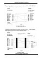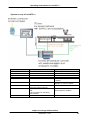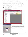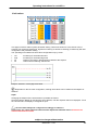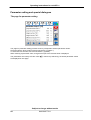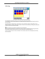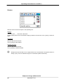
1
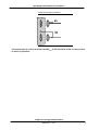
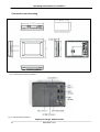
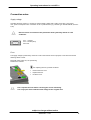
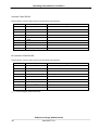
PMA Prozeß- und Maschinen-Automation GmbH
Operating terminal for extruder operation
varioECmini
Operating
Instructions
9499-040-77211
valid from 8447
Operating instructions for varioECmini
The content of this documentation was prepared and checked with utmost care.
However, PMA Prozeß- und Maschinen-Automation GmbH refuses any liability for damage which
may result from errors in the documentation. In particular, descriptions and technical data cannot
be considered as warranted features in the legal sense.
PMA Prozeß- und Maschinen-Automation GmbH is entitled to make changes of the described
product or of the documentation without notice, if these changes are made for reasons of
reliability or quality assurance, or in the interest of technical progress.
All rights of documentation are reserved by PMA Prozeß- und Maschinen-Automation GmbH. No
part of this document may be reproduced or published in any form or by any means without prior
written permission by PMA Prozeß- und Maschinen-Automation GmbH.
PMA Prozeß- und Maschinen-Automation GmbH
P.O. Box 31 02 29
D 34058 Kassel
Germany
BlueControl® is a registrated trademark of PMA GmbH
Kassel, 10.03.2005
Subject to change without notice
2
9499 040 77211
Operating instructions for varioECmini
Contents
GENERAL NOTES ..................................................................................................... 5
Safety and precautionary measures ....................................................................................................5
Commissioning/shut-down...................................................................................................................6
Unpacking the instrument.....................................................................................................................6
Electrical connections ...........................................................................................................................6
Power supply..........................................................................................................................................6
Bus cable ................................................................................................................................................6
Connections and mounting ..................................................................................................................8
CONNECTION NOTES .............................................................................................. 9
Supply voltage..........................................................................................................................................9
Fuse .........................................................................................................................................................9
Interface COM1 RS232..........................................................................................................................10
Bus interface COM2 RS485...................................................................................................................10
Connecting cable between operating terminal varioECmini COM2 (RS485) and KS vario Modbus
coupler ..................................................................................................................................................11
Connecting cable between operating terminal varioECmini COM1 (RS232) and engineering port
of KS vario controller module.............................................................................................................11
EXTRUDER OPERATION USING VARIOECMINI ..................................................... 12
System structure..................................................................................................................................12
System survey of varioECmini ..............................................................................................................13
COMMISSIONING AND BASIC CONFIGURATION OF A NEW OPERATING UNIT
.................................................................................................................................. 14
Configuration of KS vario....................................................................................................................14
OPERATOR INTERFACE ........................................................................................ 15
Fundamentals.......................................................................................................................................15
Touchscreen layout .............................................................................................................................15
Configuration of varioECmini ................................................................................................................17
BASIC PRINCIPLE OF OPERATION ...................................................................... 18
subject to change without notice
9499 040 77211
3
Operating instructions for varioECmini
The survey page...................................................................................................................................18
The controller page..............................................................................................................................19
The page for group operation.............................................................................................................20
Page for drive operation......................................................................................................................21
Safety switch-off for the drive: ...........................................................................................................21
The trend page .....................................................................................................................................22
Limit values ..........................................................................................................................................23
PARAMETER SETTING AND SPECIAL DIALOGUES ........................................... 24
The page for parameter setting ..........................................................................................................24
Self-tuning ............................................................................................................................................25
Recipes .................................................................................................................................................26
Analog input scaling............................................................................................................................27
Drive scaling.........................................................................................................................................28
Einstellung Drucksensor.....................................................................................................................29
Passwords ............................................................................................................................................30
TECHNICAL DATA .................................................................................................. 31
Subject to change without notice
4
9499 040 77211
Operating instructions for varioECmini
General notes
In conjunction with multi-channel controller KS vario, control terminal varioECmini is a very
compact solution for extruder automation. This operating note is a description of the control
terminal functionality and provides information for KS vario engineering.
a Please, also follow the operating notes for KS vario!
These operating notes are valid for the varioECmini operating terminal versions with order
number:
KSVC-111-20150
KSVC-111-20151
For versions, see data sheet. Order number
Safety and precautionary measures
This instrument was built and tested in accordance with VDE 0411 / EN 61010-1 and was
shipped in safe condition. Protection class is IP65 (front panel) and IP20 (rear cover).
The instrument complies with European guideline 89/336/EEC (EMC) and is provided with
the CE marking.
In order to maintain this condition and to ensure safe operation, the user must follow the
hints and warnings given in these operating notes and in the safety hints.
The overall equipment of machines / systems intended for the European market must meet
EN 60 204 part 1/85 (identical with VDE 0113 part 1 / 02.86).
With machines / systems intended for overseas exportation, the applicable national safety
regulations must be taken into account.
a
As compliance with the safety regulations is beyond our influence, we refuse
liability for damage resulting from failure to comply with one or several of these
regulations.
The list of safety regulations cannot be complete (machine and foreign regulations). Failure
to mention one of these regulations cannot be deemed as a waiver of its validity.
Maintenance and repair work may be done only by persons who are recognized specialists in
the sense of VDE standards, law on instrument safety, regulations for accident prevention of
the trade associations, etc.
The instrument may be operated only by trained and authorized personnel. Without
impairment of its safety, the instrument can be operated only within the permissible
environmental conditions (see data sheet).
The instrument is intended only as an operating terminal for measurement and control instruments in
technical systems.
subject to change without notice
9499 040 77211
5
Operating instructions for varioECmini
Commissioning/shut-down
Unpacking the instrument
Check, if the consignment is correct and complete and inspect the instrument for damage
due to improper handling during transport and storage.
a
If the instrument is damaged to an extent that safe operation cannot reasonably
be expected, the instrument must not be taken into operation.
a
Before installation/dismounting of the instrument, or before mounting or removal
of connectors on the instrument, control terminal varioECmini must be
disconnected completely from the supply voltage, i.e. de-energized.
Electrical connections
The electrical connections must be made in accordance with the national standards (e.g.
VDE 0100 in Germany).
For improved interference suppression, signal and data leads should be kept separate from
power supply cables. Before inserting or removing connectors on operating terminal
varioECmini, , the supply voltage must be switched off.
Power supply
Control terminal varioECmini requires an external supply voltage. Rated supply voltage
24VDC (-15%/+20%), max. power consumption 12W. Connection is via a 3-pole terminal
(e.g. Phoenix type: FRONT-MSTB, 2,5/3-ST-5,08). Note the polarity.
Bus cable
We recommend using screened data cables for bus cable, and connecting one end of the
screening to control terminal varioECmini. The D-connectors / D-sockets of control terminal
varioECmini are connected conductantly with the housing.
Subject to change without notice
6
9499 040 77211
Operating instructions for varioECmini
Cable screening connection
The connection of control terminal varioECmini to PE should be of low resistance and
as short as possible!
subject to change without notice
9499 040 77211
7
Operating instructions for varioECmini
Connections and mounting
Fig. 1: Dimensions of terminal varioECmini
Fig. 2: Rear of terminal varioECmini
Subject to change without notice
8
9499 040 77211
Operating instructions for varioECmini
Connection notes
Supply voltage
Operating terminal varioECmini requires an external supply voltage with a rating of 24V DC (-15%/+20%),
max. power consumption 12W. Connection is via a 3-pole terminal ( e.g. Phoenix type: FRONT-MSTB, 2,5/3-ST5,08)
a
Ensure correct connection to the protective earth system by means of a PE
conductor.
Pin 1: + 24VDC
Pin 2: -24VDC (Gnd)
PIN 3: PE
Fuse
The supply voltage is protected by means of a fuse in the terminal. For this purpose, a fine-wire fuse with the
following values is used:
Electrical values: 250V AC, 5A quick-acting
Dimensions: 5x20mm
gFor replacing the fuse, proceed as follows:
•
•
•
a
Remove the fuse cover.
Replace the fuse.
Re-fit the cover.
Don’t replace the fuse before removing the cause of blowing.
Use only spare fuses with the same ratings as the original one!
subject to change without notice
9499 040 77211
9
Operating instructions for varioECmini
Interface COM1 RS232
RS232 interface, 9-pole D-SUB connector with the following pin allocation:
Pin no.
Description
Signal
1
DCD
2
RXD
Receive data RS232
3
TXD
Send data RS232
4
DTR
5
GND
6
DSR
7
RTS
8
CTS
9
RI
GND
Bus interface COM3 RS485
RS485 interface, 9-pole D-SUB connector with the following pin allocation:
Pin no.
Description
Signal
1
DATA-
Inverted data signal
2
n.c.
------
3
n.c.
------
4
DATA+
5
GND
GND
6
n.c.
------
7
n.c.
------
8
n.c.
------
9
n.c.
------
Data signal
a n.c. Unused signals must remain free!
Subject to change without notice
10
9499 040 77211
Operating instructions for varioECmini
Connecting cable between operating terminal varioECmini COM3 (RS485)
and KS vario Modbus coupler
Connecting cable between operating terminal varioECmini COM1 (RS232)
and engineering port of KS vario controller module
subject to change without notice
9499 040 77211
11
Operating instructions for varioECmini
Extruder operation using varioECmini
System varioECmini with multi-channel controller KS vario is a very compact solution for
extruder automation. Due to the PLC integrated in the varioECmini operating terminal, the
complete extruder can be operated and monitored by KS vario without the need for an
additional automation system. The varioECmini version provides operation of up to 12
temperature control loops, melt temperature and melt pressure measurement and monitoring
as well as master drive control and monitoring.
System structure
•
•
•
•
•
•
Operating/control terminal:
• TPC-6x: 5,7-inch colour DSTN for varioECmini
Integrated soft PLC with visualization functions
• Sequence program with limit monitoring functions, drive control etc.
• Complete touchscreen operator interface
KS vario for temperature control and melt temperature measurement
Additional digital I/O modules for enable signals, feedback signals, alarms, external controls
Additional analog input modules for melt pressure, melt temperature (optional), e.g. drive process
values (pairwise galvanic isolation)
Additional analog output modules for drive setpoints (pairwise galvanic isolation)
Subject to change without notice
12
9499 040 77211
Operating instructions for varioECmini
System survey of varioECmini
Product
Display
Touch
Keyboard
Options
Temperature controller
Mini
5,7-inch; 320x240 colour
yes
Drives
1
Drive control
Manual,
slave with external setpoint
Speed,
load,
external setpoint or melt temp.,
melt pressure
-
Measurements
Process control
Signals/instrument
TPC touch panel computer
Web server, data exchange
8 .. 12, 1 thereof for melt temp.
Thermocouple inputs or PT100 (for
all inputs)
Analog inputs/outputs:
Setpoint: 0..10V or 0..20mA
Inputs: 0..10V or 0 ..20mA
pairwise galvanic isolation
subject to change without notice
9499 040 77211
13
Operating instructions for varioECmini
Commissioning and basic configuration of a new operating unit
Configuration of KS vario
At first, configure your KS vario by using the engineering tool
BlueControl®.
g
•
•
With a Modbus version: set Baudrate 38400 and address 1.
Specify 5ms in "Modem delay".
+When downloading from engineering tool BlueControl®
into KS vario, please, don’t forget to include the interface
parameters (check ‘Transfer communication parameters‘).
Subject to change without notice
14
9499 040 77211
Operating instructions for varioECmini
Operator interface
Fundamentals
The operator interface of operating terminal varioECmini is divided into several levels.
The start-up page is followed automatically by the operating level. The dialogue pages of the operating
level are selectable directly by touching buttons. The pages for parameter setting and configuration
level are selected by selection menus.
Touchscreen layout
Heating
feedback
Process val.
Display/working
area
Drive feedback
Direct selection
operat. level
Page-dependant
function buttons
Process value bar
Display of 4 process values: extruder r.p.m., master drive load, melt temperature, melt pressure
Feedback indexes
Heating feedback is with the output for the main heating contactor set.
Drive control feedback for drive ok.
subject to change without notice
9499 040 77211
15
Operating instructions for varioECmini
Buttons for direct selection
Buttons for selection of operating pages:
alarm page, red when alarms are active
selection menu
main operating pages for temperatures
main operating page for drive, red with the drive in stop mode
(melt pressure switch-off, torque, low temperature switch-on limit
return to the previous page (e.g. back to the menu from the page
for parameter setting)
Page-dependent function buttons
Buttons for operation of special functions on the pages, or for selecting further sub-pages! Additionally,
information on the page content is provided (e.g. displayed values)!
Subject to change without notice
16
9499 040 77211
Operating instructions for varioECmini
Configuration of varioECmini
The operating terminal is connected with the MODBUS coupler of controller KS vario by a suitable RS
485 cable between COM3 and the connection on the bus coupler.
When using KS vario with other fieldbus couplers, e.g. Profibus, connection is by means of the
relevant RS 232 cable between COM1 and the diagnostic interface of the KS vario controller module.
During initial commissioning, additional settings in the operating terminal are required to ensure safe
operation.
The basic settings can be made on dialogue page ’Setup‘ in the configuration menu. Setting is done
by touching the relevant field.
Please, configure according to the following order:
§
§
§
§
§
§
Select the interface (switch over by touching field ’RS485‘): RS485 for Modbus units and RS232
for all other units.
Select the language using the language selection key.
Number of required heating zones (display of all other zones is suppressed).
Now, you can actuate button [defaults].
The terminal generates the address allocation of controller and operating terminal and the
standard descriptions for the control channels.
Switch over °C <-> °F: Touch the field to change the temperature unit.
Slot number for the digital input module: for correct allocation of digital input channels, the position
of the digital input module (e.g.: DI16/24) must be entered. The controller module is always
inserted in slot 0.
If necessary, channel descriptions and address allocation can be matched individually.
§
§
§
Name:
Device:
Channel
channel description with max. 10 characters
Modbus coupler address
channel number in the relevant KS vario
Selection of the other control channels is possible using the arrow buttons.
+The texts for the process value line can also be edited on this page.
Button <Save> (disk icon) can be actuated to save the settings on disk.
g Please, don’t forget to store the basic setting !
subject to change without notice
9499 040 77211
17
Operating instructions for varioECmini
Basic principle of operation
The survey page
The survey page provides display of process values, setpoints, zone number and output in per cent as
a bargraph for the controller channels.
In case of alarms, the status of the relevant channel is displayed in colour as follows:
Limit alarms
Limit 3
Limit 2
Limit 1
Sensor break
Low alarm
blue blinking
blue
light blue
Exceeded tolerance
orange blinking
orange
light orange
High alarm
red blinking
red
light red
"ERR" is displayed blinkingly in black / white.
With the controller switched off, the process value is displayed with gray background. Fur unused
channels (+Configuration), display of values and zone numbers is suppressed.
Direct selection of important dialogues
By touching a displayed measured value, the page containing detailed information on the relevant
channel is displayed.
For channel switch-on/off, change to the main operating page via [ I/O ].
The buttons for heating on, heating off and for stand-by are available on this page.
Touch button <Select> for process value display switch-over between temperature, output in per cent,
control deviation and heating current. Indication which process value is displayed is beside the select
button.
Subject to change without notice
18
9499 040 77211
Operating instructions for varioECmini
The controller page
On the page for controller operation per channel, the most important information for a controller is
displayed and can be changed.
Green status display:
ON
W2
The controller is switched on (green); can be switched off by touching.
The controller operates with the 2nd setpoint; switch-over is possible by touching.
Touch the setpoint to display a keypad for setpoint entry.
During manual operation, the manual correcting value is shown in this position.
Touch the arrow buttons to go to the different controller channels.
The instantaneously displayed channel is indicated on the bottom of the page.
g If the controller setpoint does not correspond to the adjusted operating setpoint e.g. due to an
active setpoint ramp, the setpoint is displayed with a different colour.
In this case, the operating setpoint is displayed below the setpoint for input.
subject to change without notice
9499 040 77211
19
Operating instructions for varioECmini
The page for group operation
This page can be used for switching on or off all control loops or only single heating loops.
Buttons on [ on ], [ off ] and [ w2 ] always influence all channels the display fields of which are shown
with bold border lines.
Normally, all used zones are selected.
For omission, channels must be de-selected purposefully.
Status indication
Green
Blue
Gray
The relevant controller is active.
Lowering setpoint w2 of the relevant channel is active.
The controller is switched off (coff).
Subject to change without notice
20
9499 040 77211
Operating instructions for varioECmini
Page for drive operation
The r.p.m. of the master drive can be changed by touching the up or down button (for step width +
drive scaling) or by direct entry of the setpoint on this page.
New setpoint entries are possible only with the drive switched on. If the drive is switched off (button for
drive OFF feedback), the setpoint is always 0! With drive switch-on limit activated, drive switch-on is
not possible!
Safety switch-off for the drive:
Drive safety switch-off is at two levels:
§
§
in the terminal PLC
as direct wiring on KS vario
Switch-off is indicated as limit value error message on the alarm page and by red motor background
on the button for direct operation! For correct handling of this function, the appropriate settings (limit
value for enabling, stored absolute limit value alarm) in KS vario are required.
a KS vario must always be configured accordingly in advance!
a Cold start inhibit
To prevent screw starting with insufficient melt temperature, the drive is disabled via the absolute
temperature limit values LIM 2 of KS vario, whereby all controller channels provided in the
configuration are taken into account. The required limit values must be adjusted on the page for
configuration + of the limit values. For omission of single zones from monitoring, the limit values of
these zones must be changed accordingly.
a Switch-off in case of excessive load
For max. load, a warning alarm and a switch-off alarm are provided. The limit values must be adjusted
on the page for configuration + of the limit value. Use the LIM 2 contact of KS vario for the pre-
subject to change without notice
9499 040 77211
21
Operating instructions for varioECmini
alarm and the LIM 3 contact of the relevant input for the switch-off alarm. Additionally, this alarm
contact is switched to a digital input which sets the drive setpoint to 0. Thereby, switch-off is ensured
even in case of terminal (PLC) failure.
a High melt pressure switch-off
As with the load, a warning alarm and a switch-off alarm are provided for the max. melt pressure. The
limit values must be adjusted on the page for configuration + of the limit values. Use LIM 2 contact
of KS vario for the warning alarm and the LIM 3 contact of the relevant input for the switch-off alarm.
Additionally, this alarm contact is switched to a digital input which switches the drive setpoint output
off. Thereby, switch-off is ensured even in case of terminal (PLC) failure.
The trend page
The setpoint and process value curves over the last 40 minutes are displayed on the trend page.
Additionally, a horizontal cursor indicates the instantaneously active setpoint.
Selection of a different channel is possible by touching the arrow buttons, or by direct entry in the
bottom line. Scaling of the Y-axis is done automatically. The actual value is displayed on the left. Apart
from the temperature trends, the relevant drive values can be selected.
Subject to change without notice
22
9499 040 77211
Operating instructions for varioECmini
Limit values
This page is used for alarm system parameter setting. Three limit values for each channel can be
entered. The monitoring mode (low, high limit monitoring or tolerance checking) is defined by KS vario
configuration and parameter setting.
The operating unit indicates the limit value configuration only by colour.
§
§
§
§
low
high
tol
off
monitoring for exceeded low limit
monitoring for exceeded high limit
tolerance checking in both directions related to the setpoint
channel limit monitoring switched off
Example: Channels 1..4 of the page shown above
g Dependent on the KS vario configuration, low/high limit values can be related to the setpoint or
absolute.
Input:
Changing the setpoint of the active alarms is possible as follows:
Scroll through the display by touching the arrow buttons, until the required channel is displayed. Touch
the relevant value for display of a keypad for input.
a KS vario must always be configured accordingly in advance !
In particular, the switch-off alarm limits must be adjusted as absolute values and set to the
relevant absolute limit value.
subject to change without notice
9499 040 77211
23
Operating instructions for varioECmini
Parameter setting and special dialogues
The page for parameter setting
The page for parameter setting provides a survey of important channel parameter values.
Scroll through the list by means of the arrow buttons ( up/down ).
To select the next channel, touch arrow buttons ( right/left ).
When touching a parameter value, a keypad for input of the relevant value is displayed.
The parameters are read by KS vario. After + control loop self-tuning, the actual parameter values
are displayed on this page.
Subject to change without notice
24
9499 040 77211
Operating instructions for varioECmini
Self-tuning
The operating unit supports starting of single and group self-tuning attempts.
Touch button [ sel ] for channel selection. For single self-tuning, touch the relevant channel in the list
with your finger.
After selecting the required zones, the selection can be activated in KS vario using button [ start ].
Whilst self-tuning is running, self-tuning of further channels can be started by touching [ sel ] and [ start
]. Button [ stop ] cancels all self-tunings.
g For self-tuning, the relevant controllers must be switched on.
When all selected controllers are switched off, button [ manual ] is displayed. By touching this button,
all selected controllers are switched on in manual mode with correcting variable =0.
Unless the select function is active, the status of the relevant channel can be displayed by touching
the channel field.
subject to change without notice
9499 040 77211
25
Operating instructions for varioECmini
Recipes
Settings can be stored as recipes in the operating unit.
Storage:
Touch line "File: __ " and enter a file name.
Already existing files can be overwritten simply by selection from the list. Touch [ write ] to save the
data.
Read-back:
Select a data set from the list.
Touch [ read ] for data read-in.
Deleting data sets:
Select a data set from the list.
Touch [ delete ] to delete the data.
g
Recipes are saved as files on the compact flash card. The extension of recipe file names is
always (.ksv). The max. filename length is 10 characters (without extension)
Subject to change without notice
26
9499 040 77211
Operating instructions for varioECmini
Analog input scaling
The analog inputs for melt pressure and melt temperature can be adjusted by means of scaling.
The KS vario 2-point corrective function is used. Enter the input span start and end (e.g. 0 or
10V/20mA) and the required display span start and end value (e.g. 400° at 10V input signal).
g
Selection whether to use current or voltage input must be done in KS vario.
subject to change without notice
9499 040 77211
27
Operating instructions for varioECmini
Drive scaling
In addition to process value scaling (r.p.m. and load) for the drive, analog output scaling for the r.p.m.
setpoint is also done on this page. The r.p.m. value is in the form of simple KS vario output scaling.
Apart from scaling of analog values, the step width for r.p.m. changing is set by means of the tipping
buttons on this page.
g
The step width is stored automatically and remains unchanged also after power failure.
a The scaling should be changed only with the drive stopped to prevent setpoint step
changes due to re-scaling.
Subject to change without notice
28
9499 040 77211
Operating instructions for varioECmini
Pressure transducer adjustment
It’s possible to connect pressure sensors with standard 0..10V interface (+ ‚ Analog input scaling’)
or 6 wire presssure transducers with mV output. On this page you will find the functions to setup the
pressure transducer.
In the edit fields at the top of the page, it’s posssible to define the range auf the transducer (e.g. 7500
psi). In the box below, the actual measured value will be displayed. The kind of the value and the
actual working function are displayed in the lowest box.
The button ‚mV‘ is used to switch the displayed value to voltage measurement (mV). With this
function, it is possible to measure the real output of the pressure transducer (e.g. to calibrate the 0
point and the ‚80%‘ point).
With the button ‚80%‘ the relais output for the 80% calibration resistor of the transducer ist activated.
It is possible to perform an automatically adjustment and calibration of the transducer measurement
range. With the activation of the button ‚auto‘, the following actions will be done:
•
•
•
•
•
switch to measurement range mV
measure the zero point
activate the calibration resistor
measure the 80% point
calculate and save the new scaling values 0..100% for the analog input
g
The scaling parameter are stored on the page ‚ Analog input scaling’ automatically
They remain unchanged even after power failure.
a While using the mV Display the system works with unscaled values. Thereby it’s
possible, that machinery savety function takes action!
subject to change without notice
9499 040 77211
29
Operating instructions for varioECmini
Passwords
Data entries at the varioECmini operating unit can be disabled via three access levels.
The parameter menu on the main operating page can be used to start a password dialogue.
This dialogue offers three user levels. With a new operating unit, no passwords are stored and all data
are accessible (level 3).
To activate the user management, passwords for disabling user levels must be specified.
g
At user level 1 (operator), setpoint entry is possible. At this user level, return to the survey
page from all pages is after a time of 30 sec. This ensures that the main operating page for
extruder operation is displayed again at the latest after 30 sec. At all user levels > 1, automatic
returning is omitted, in order to prevent e.g. interfering with parameter setting or set-up.
USER LEVELS
Level 1:
Level 2:
Level 3:
Operator
Technician
Default settings
Setpoint, heating on/off, ...
Parameters, limit values, recipes...
Configuration of the operating unit, scalings ...
Activating a user level and password changing:
The passwords of currently enabled level and of lower levels can be changed.
Definition of a new password is by entering a password twice for the relevant user level. “#” is used as
a separator between the two passwords.
Example
Enter "1234#1234" in line "Level 2" to define "1234" as a new password for user level 2. To delete a
password, simply enter "#".
Log-in and log-out:
Open the password dialogue via the parameter menu on the survey page.
If a user has already logged in, or if no passwords are stored, the actual user level is indicated via the
status fields.
For logging out, simply touch [ LOGOUT ].
To log in, enter the valid password for the required user level.
Leave the dialogue with [ EXIT ].
Subject to change without notice
30
9499 040 77211
Operating instructions for varioECmini
Technical data
COMPUTER
CPU: Intel XscalePXA270 (416MHz)
cooling without fan
64-Mbyte on-board RAM
64-Mbyte on-board flash memory
DISPLAY
5,7-inch FSTN colour LC display
QVGA 320 x 240 pixel resolution
256 colours, approx. 180 cd/qm
resistive touch
INTERFACES
Connection for KSVARIO Modbus coupler (COM3)
Type: RS485, 9-pole Sub-D connector
Max. cable length: 1000m
Connection for KS vario BlueControl interface (COM1)
Type: V.24 / RS232, 9-pole Sub-D connector
Max. cable length: 3m
Serial Interface (COM2)
Typ: V.24 / RS232, 9 pol. Sub-D connector
Max. cable length: 12m
Network
Ethernet interface (10 /100Base-T)
USB interface
1 x USB host
1 x USB client
Memory extension
1 x compact flash card type I
POWER SUPPLY
Operating voltage: 24 V DC ≤ 20W
Protection class III (protective low voltage)
ENVIRONMENTAL CONDITIONS
Permissible temperatures
Operating temperature
0...50°C
Storage/transport
-20...60 °C
CLIMATIC CATEGORY:
Relative humidity: 10 ..95 % at 40°C, no condensation
subject to change without notice
9499 040 77211
31
Operating instructions for varioECmini
INFLUENCING FACTORS
Supply voltage
Without effect. No loss of configuration data in case of power failure (flash PROM storage).
Vibration test
Sinusoidal vibrations according to
IEC 60068-2-6; EN 60068-2-6;
Load: 2g, 1 h for each space direction
Shock test
acc. to IEC 60068-2-27; EN 60068-2-27
Load: 10g during 11 ms, half-sinusoidal wave,
three shocks in each space direction and orientation
ELECTROMAGNETIC COMPATIBILITY
Noise immunity test according to EN 50082-2
All interface cables must be screened.
Noise emission test according to EN 50081-2
Housing: EN 55011 -class A
GENERAL
Housing
Dimensions (WxHxD): 195x148x45 [mm]
Panel cut-out: 188x141 [mm]
Weight
approx. 0,8 kg
Protection type
Front: IP 65
Rear: IP 20
Safety
Meets EN 61010-1 (VDE 0411-1):
Overvoltage category II
Degree of contamination 2
Operating voltage range 50 V
Protection class III
CE marking
Meets the guidelines for electromagnetic compatibility and the low-voltage guideline.
Accessories delivered with the unit
Connection terminal for the operating voltage
Mounting accessories
Subject to change without notice
32
9499 040 77211